2000 DODGE NEON battery location
[x] Cancel search: battery locationPage 365 of 1285
first turn) will cause all vehicle doors to unlock elec-
trically. When this feature is disabled, all vehicle
doors will be unlocked electrically upon the first turn
of a key cylinder to the UNLOCK position. The vehi-
cle is locked electrically by turning the key cylinder
to the LOCK position once, regardless of the state of
the double activation unlock feature.
POWER DOOR LOCKS
The Remote Keyless Entry (RKE) Module actuates
the power door lock relays when a door lock switch is
activated. If the door lock switch is pressed for longer
than eight consecutive seconds, the RKE module will
de-energize the door lock motors.
The system includes the rolling door locking fea-
ture. The vehicle is shipped with the system enabled.
When the system is disabled the door locks will work
by use of the door lock switches and the Remote Key-
less Entry system only. When the rolling door lock
system is enabled, the RKE module will automati-
cally lock all the vehicle doors when all of the follow-
ing conditions are met:
²All doors are closed
²The vehicle speed exceeds 15 +/- 1 mph.
²The throttle position sensor tip-in is greater
than 10 +/- 2 degrees.
The RKE module will automatically re-lock all
doors if the above conditions are met and if any of
the doors become ajar and then closed again.
The enabling/disabling of the rolling door lock fea-
ture is customer programmable, as well as program-
mable with the DRB IIItscan tool.
The power lock motors are also equipped with a
thermal protection system which prevents the motors
from burning out. The motors may chatter if they are
continuously activated.
CHILD PROTECTION LOCKS
The child protection locks are on the rear doors
only. The lock, when engaged, will disable the inside
door handle from opening the door. The lock is part
of the latch/lock assembly. The lock is engaged by
moving a lever that is located on the rearward inside
edge of the door.
DOOR LOCK INHIBIT
With the key in the ignition switch and the driver
door open, the Remote Keyless Entry (RKE) Modulewill ignore the command to lock the power door locks
via the interior driver door lock switch. Once the key
is removed, or the driver door is closed, the RKE
module will allow the power door locks to lock via the
interior door lock switches.
DIAGNOSIS AND TESTING
DOOR LOCK MOTOR
(1) Make certain battery is in normal condition
and fuses powering the RKE module aren't blown
before circuits are tested.
(2) To determine which motor is faulty, check each
individual door for electrical lock and unlock or dis-
connect the motor connectors one at a time, while
operating the door lock switch.
(3) In the event that none of the motors work, the
problem maybe caused by a shorted motor, a bad
switch or a bad relay internal to the RKE module.
Disconnecting a defective motor will allow the others
to work.
(4) To test an individual door lock motor, discon-
nect the electrical connector from the motor.
(5) To lock the door, connect a 12 volt power source
to one pin of the lock motor and a ground wire to the
other pin.
(6) To unlock the door, reverse the wire connec-
tions at the motor pin terminals.
(7) If these results are NOT obtained, replace the
motor.
DOOR LOCK SWITCH
(1) Remove the switch from its mounting location,
and disconnect from vehicle wiring harness. Refer to
Door Lock Switch Removal and Installation in this
section.
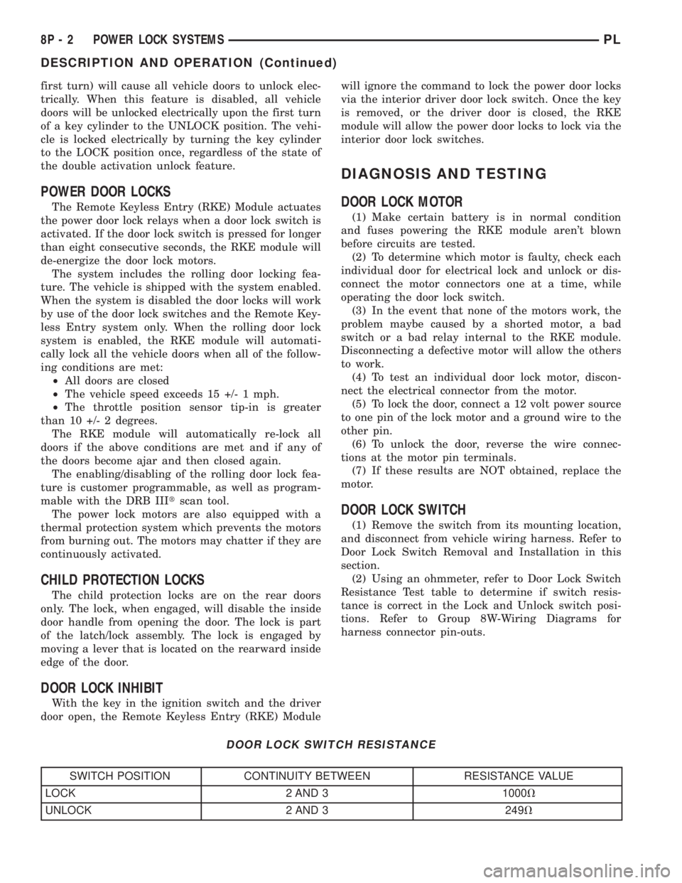
(2) Using an ohmmeter, refer to Door Lock Switch
Resistance Test table to determine if switch resis-
tance is correct in the Lock and Unlock switch posi-
tions. Refer to Group 8W-Wiring Diagrams for
harness connector pin-outs.
DOOR LOCK SWITCH RESISTANCE
SWITCH POSITION CONTINUITY BETWEEN RESISTANCE VALUE
LOCK 2 AND 3 1000V
UNLOCK 2 AND 3 249V
8P - 2 POWER LOCK SYSTEMSPL
DESCRIPTION AND OPERATION (Continued)
Page 370 of 1285
INSTALLATION
For installation, reverse above the procedures.
SPECIFICATIONS
TRANSMITTER BATTERY
The transmitter has two 3 volt batteries, which can
be removed and replaced without special tools. Insert
a dime in the side slot of the transmitter and twist.
The halves should separate and the batteries are
stacked on top of each other (Fig. 1). The batteries
are available at local retail stores. Recommended bat-
teries are Panasonic CR 2016 or equivalent. Battery
life is approximately two years. Transmitter pro-
gramming is not necessary after replacement of the
transmitter batteries.
TRANSMITTER RANGE
Operation range is within 7 meters (23 ft.) of the
module/receiver.
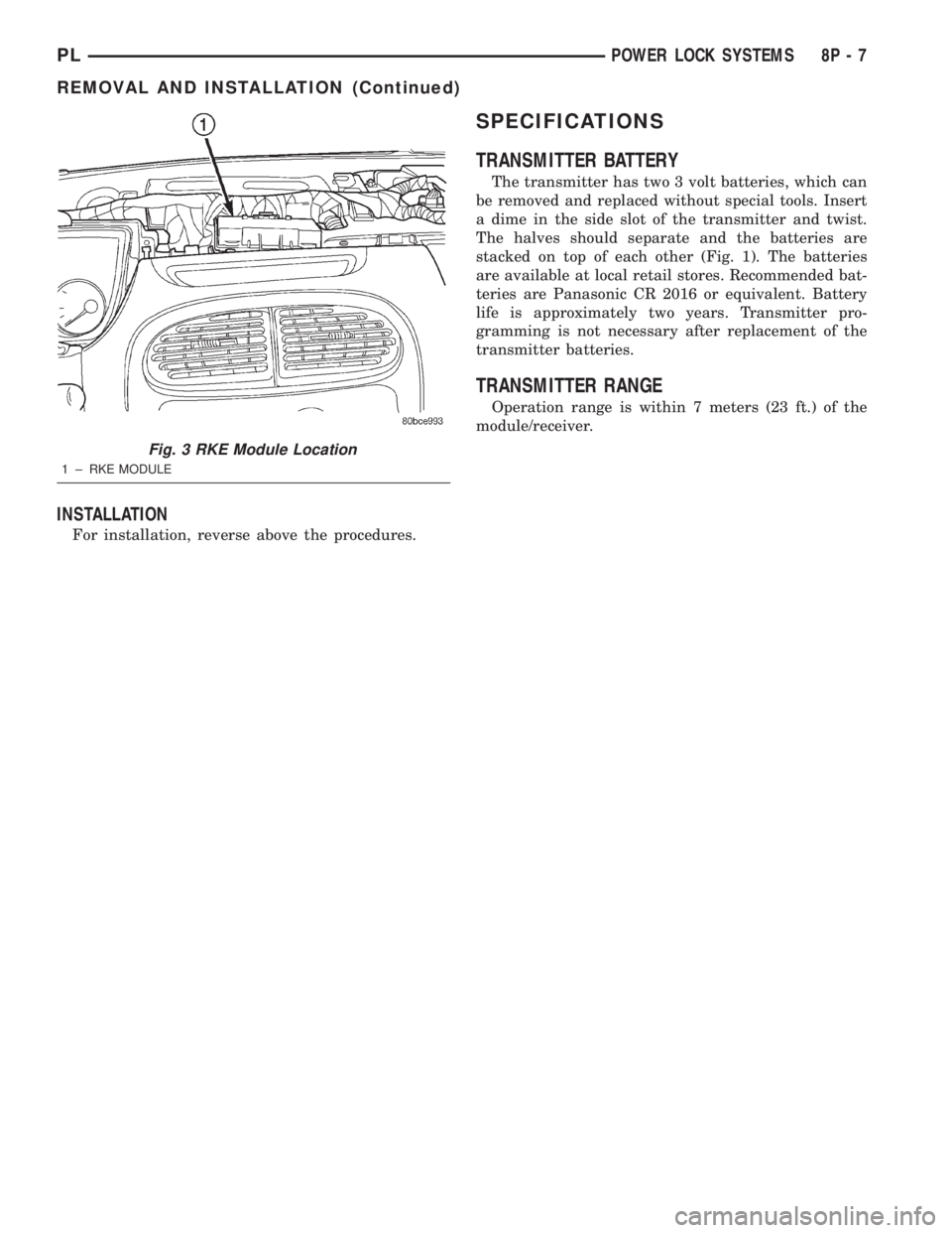
Fig. 3 RKE Module Location
1 ± RKE MODULE
PLPOWER LOCK SYSTEMS 8P - 7
REMOVAL AND INSTALLATION (Continued)
Page 378 of 1285
REMOVAL AND INSTALLATION
DOOR CYLINDER LOCK SWITCH
REMOVAL
(1) Refer to Group 23, Body for door trim and
water shield Removal and Installation.
(2) Remove illuminated entry switch wiring clip
and disconnect connector.
(3) Remove door cylinder lock switch from door
handle.
INSTALLATION
For installation reverse the above procedures.
HOOD AJAR SWITCH
REMOVAL
(1) Open hood.
(2) Disconnect and isolate the battery negative
remote cable (Fig. 3).
(3) Using a trim stick (special tool #C-4755) or
equivalent, gently pry switch up and out of mounting
bracket.
(4) Disconnect wire harness connector from hood
ajar switch.
(5) Remove switch from vehicle.
INSTALLATION
For installation reverse above procedures.
SENTRY KEY IMMOBILIZER MODULE (SKIM)
WARNING: ON VEHICLES EQUIPPED WITH AIR-
BAGS, REFER TO GROUP 8M - PASSIVE
RESTRAINT SYSTEMS BEFORE ATTEMPTING ANY
STEERING WHEEL, STEERING COLUMN, OR
INSTRUMENT PANEL COMPONENT DIAGNOSIS OR
SERVICE. FAILURE TO TAKE THE PROPER PRE-
CAUTIONS COULD RESULT IN ACCIDENTAL AIR-
BAG DEPLOYMENT AND POSSIBLE PERSONAL
INJURY.
REMOVAL
(1) Disconnect and isolate the battery negative
remote cable (Fig. 3).
(2) Remove Lower Instrument Panel Cover. Refer
to Group 8E-Instrument Panel and Systems, Lower
Instrument Panel Cover Removal and Installation.
(3) Remove the steering column upper and lower
shrouds. Refer to Group 8E-Inatrument Panel and
Systems, Steering Column Shroud Removal and
Installation.
(4) Disengage the steering column wire harness
from the Sentry Key Immobilizer Module (SKIM).
(5) Remove the two screws securing the SKIM
module to the top of the steering column.
(6) Rotate the SKIM and its mounting bracket
upwards and then to the side away from the steering
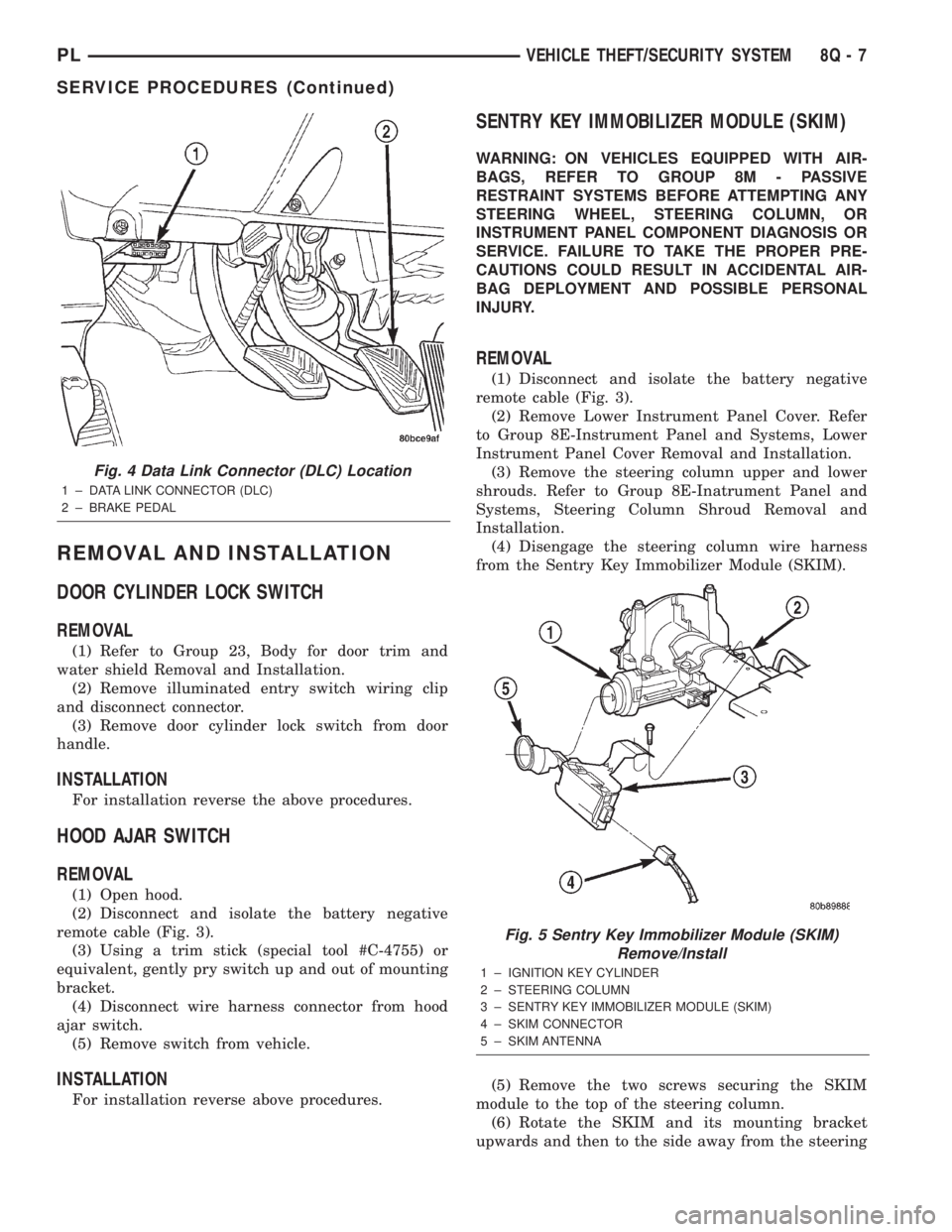
Fig. 4 Data Link Connector (DLC) Location
1 ± DATA LINK CONNECTOR (DLC)
2 ± BRAKE PEDAL
Fig. 5 Sentry Key Immobilizer Module (SKIM)
Remove/Install
1 ± IGNITION KEY CYLINDER
2 ± STEERING COLUMN
3 ± SENTRY KEY IMMOBILIZER MODULE (SKIM)
4 ± SKIM CONNECTOR
5 ± SKIM ANTENNA
PLVEHICLE THEFT/SECURITY SYSTEM 8Q - 7
SERVICE PROCEDURES (Continued)
Page 386 of 1285
POWER MIRRORS
TABLE OF CONTENTS
page page
GENERAL INFORMATION
INTRODUCTION..........................1
DIAGNOSIS AND TESTING
POWER FOLD AWAY MIRROR SWITCH TEST...1POWER FOLD AWAY MIRROR MOTOR........1
REMOVAL AND INSTALLATION
POWER FOLD-AWAY MIRROR SWITCH.......1
POWER FOLD-AWAY MIRROR...............2
GENERAL INFORMATION
INTRODUCTION
These vehicles may be equipped with Power Fold
Away Mirrors. The vehicle has an additional switch
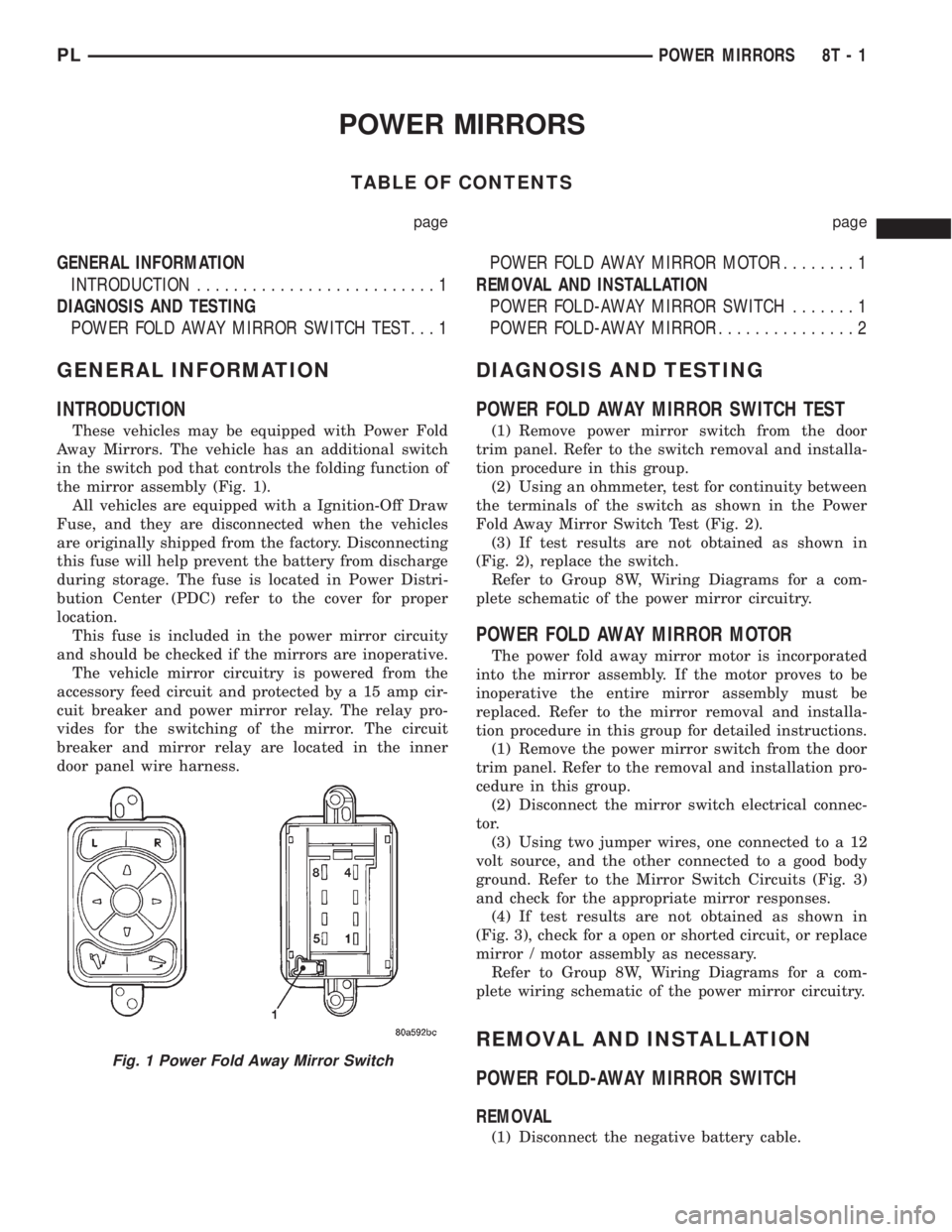
in the switch pod that controls the folding function of
the mirror assembly (Fig. 1).
All vehicles are equipped with a Ignition-Off Draw
Fuse, and they are disconnected when the vehicles
are originally shipped from the factory. Disconnecting
this fuse will help prevent the battery from discharge
during storage. The fuse is located in Power Distri-
bution Center (PDC) refer to the cover for proper
location.
This fuse is included in the power mirror circuity
and should be checked if the mirrors are inoperative.
The vehicle mirror circuitry is powered from the
accessory feed circuit and protected by a 15 amp cir-
cuit breaker and power mirror relay. The relay pro-
vides for the switching of the mirror. The circuit
breaker and mirror relay are located in the inner
door panel wire harness.
DIAGNOSIS AND TESTING
POWER FOLD AWAY MIRROR SWITCH TEST
(1) Remove power mirror switch from the door
trim panel. Refer to the switch removal and installa-
tion procedure in this group.
(2) Using an ohmmeter, test for continuity between
the terminals of the switch as shown in the Power
Fold Away Mirror Switch Test (Fig. 2).
(3) If test results are not obtained as shown in
(Fig. 2), replace the switch.
Refer to Group 8W, Wiring Diagrams for a com-
plete schematic of the power mirror circuitry.
POWER FOLD AWAY MIRROR MOTOR
The power fold away mirror motor is incorporated
into the mirror assembly. If the motor proves to be
inoperative the entire mirror assembly must be
replaced. Refer to the mirror removal and installa-
tion procedure in this group for detailed instructions.
(1) Remove the power mirror switch from the door
trim panel. Refer to the removal and installation pro-
cedure in this group.
(2) Disconnect the mirror switch electrical connec-
tor.
(3) Using two jumper wires, one connected to a 12
volt source, and the other connected to a good body
ground. Refer to the Mirror Switch Circuits (Fig. 3)
and check for the appropriate mirror responses.
(4) If test results are not obtained as shown in
(Fig. 3), check for a open or shorted circuit, or replace
mirror / motor assembly as necessary.
Refer to Group 8W, Wiring Diagrams for a com-
plete wiring schematic of the power mirror circuitry.
REMOVAL AND INSTALLATION
POWER FOLD-AWAY MIRROR SWITCH
REMOVAL
(1) Disconnect the negative battery cable.
Fig. 1 Power Fold Away Mirror Switch
PLPOWER MIRRORS 8T - 1
Page 401 of 1285
WARNING: DO NOT ALLOW FLAME OR SPARKS
NEAR THE BATTERY. GASES ARE ALWAYS
PRESENT IN AND AROUND THE BATTERY.
WARNING: ALWAYS REMOVE RINGS, WATCHES,
LOOSE HANGING JEWELRY, AND LOOSE CLOTH-
ING.
TAKE OUTS
The abbreviation T/O is used in the component
location section to indicate a point in which the wir-
ing harness branches out to a component.
ELECTROSTATIC DISCHARGE (ESD) SENSITIVE
DEVICES
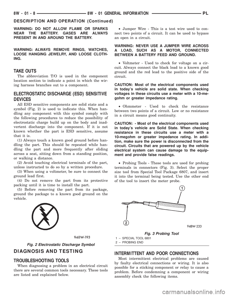
All ESD sensitive components are solid state and a
symbol (Fig. 2) is used to indicate this. When han-
dling any component with this symbol comply with
the following procedures to reduce the possibility of
electrostatic charge build up on the body and inad-
vertent discharge into the component. If it is not
known whether the part is ESD sensitive, assume
that it is.
(1) Always touch a known good ground before han-
dling the part. This should be repeated while han-
dling the part and more frequently after sliding
across a seat, sitting down from a standing position,
or walking a distance.
(2) Avoid touching electrical terminals of the part,
unless instructed to do so by a written procedure.
(3) When using a voltmeter, be sure to connect the
ground lead first.
(4) Do not remove the part from its protective
packing until it is time to install the part.
(5) Before removing the part from its package,
ground the package to a known good ground on the
vehicle.
DIAGNOSIS AND TESTING
TROUBLESHOOTING TOOLS
When diagnosing a problem in an electrical circuit
there are several common tools necessary. These tools
are listed and explained below.²Jumper Wire - This is a test wire used to con-
nect two points of a circuit. It can be used to bypass
an open in a circuit.
WARNING: NEVER USE A JUMPER WIRE ACROSS
A LOAD, SUCH AS A MOTOR, CONNECTED
BETWEEN A BATTERY FEED AND GROUND.
²Voltmeter - Used to check for voltage on a cir-
cuit. Always connect the black lead to a known good
ground and the red lead to the positive side of the
circuit.
CAUTION: Most of the electrical components used
in today's vehicle are solid state. When checking
voltages in these circuits use a meter with a 10-me-
gohm or greater impedance rating.
²Ohmmeter - Used to check the resistance
between two points of a circuit. Low or no resistance
in a circuit means good continuity.
CAUTION: - Most of the electrical components used
in today's vehicle are Solid State. When checking
resistance in these circuits use a meter with a
10-megohm or greater impedance rating. In addi-
tion, make sure the power is disconnected from the
circuit. Circuits that are powered up by the vehicle
electrical system can cause damage to the equip-
ment and provide false readings.
²Probing Tools - These tools are used for probing
terminals in connectors (Fig. 3). Select the proper
size tool from Special Tool Package 6807, and insert
it into the terminal being tested. Use the other end
of the tool to insert the meter probe.
INTERMITTENT AND POOR CONNECTIONS
Most intermittent electrical problems are caused
by faulty electrical connections or wiring. It is also
possible for a sticking component or relay to cause a
problem. Before condemning a component or wiring
assembly check the following items.
Fig. 2 Electrostatic Discharge Symbol
Fig. 3 Probing Tool
1 ± SPECIAL TOOL 6801
2 ± PROBING END
8W - 01 - 8 8W - 01 GENERAL INFORMATIONPL
DESCRIPTION AND OPERATION (Continued)
Page 660 of 1285
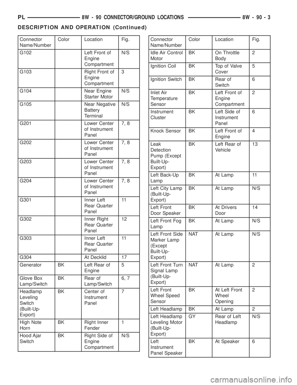
Connector
Name/NumberColor Location Fig.
G102 Left Front of
Engine
CompartmentN/S
G103 Right Front of
Engine
Compartment3
G104 Near Engine
Starter MotorN/S
G105 Near Negative
Battery
TerminalN/S
G201 Lower Center
of Instrument
Panel7, 8
G202 Lower Center
of Instrument
Panel7, 8
G203 Lower Center
of Instrument
Panel7, 8
G204 Lower Center
of Instrument
Panel7, 8
G301 Inner Left
Rear Quarter
Panel11
G302 Inner Right
Rear Quarter
Panel12
G303 Inner Left
Rear Quarter
Panel11
G304 At Decklid 17
Generator BK Left Rear of
Engine5
Glove Box
Lamp/SwitchBK Rear of
Lamp/Switch6, 7
Headlamp
Leveling
Switch
(Built-Up-
Export)BK Center of
Instrument
Panel7
High Note
HornBK Right Inner
Fender1
Hood Ajar
SwitchBK Right Side of
Engine
CompartmentN/SConnector
Name/NumberColor Location Fig.
Idle Air Control
MotorBK On Throttle
Body2
Ignition Coil BK Top of Valve
Cover5
Ignition Switch BK Rear of
Switch6
Inlet Air
Temperature
SensorBK Left Front of
Engine
Compartment2
Instrument
ClusterBK Left Side of
Instrument
Panel6
Knock Sensor BK Left Front of
Engine4
Leak
Detection
Pump (Except
Built-Up-
Export)BK Left Rear of
Vehicle13
Left Back-Up
LampBK At Lamp 11
Left City Lamp
(Built-Up-
Export)BK At Lamp N/S
Left Front
Door SpeakerBK At Drivers
Door14
Left Front Fog
LampBK At Lamp N/S
Left Front Side
Marker Lamp
(Except
Built-Up-
Export)NAT At Lamp N/S
Left Front Turn
Signal Lamp
(Built-Up-
Export)NAT At Lamp 2
Left Front
Wheel Speed
SensorBK At Left Front
Wheel
Opening2
Left Headlamp BK At Lamp 2
Left Headlamp
Leveling Motor
(Built-Up-
Export)GY Rear of Left
HeadlampN/S
Left
Instrument
Panel SpeakerBK At Speaker 6
PL8W - 90 CONNECTOR/GROUND LOCATIONS 8W - 90 - 3
DESCRIPTION AND OPERATION (Continued)
Page 679 of 1285
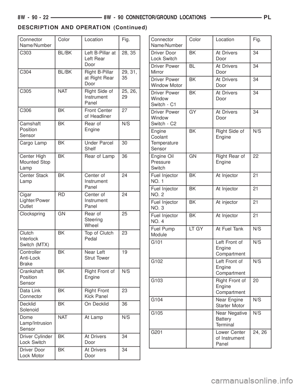
Connector
Name/NumberColor Location Fig.
C303 BL/BK Left B-Pillar at
Left Rear
Door28, 35
C304 BL/BK Right B-Pillar
at Right Rear
Door29, 31,
35
C305 NAT Right Side of
Instrument
Panel25, 26,
29
C306 BK Front Center
of Headliner27
Camshaft
Position
SensorBK Rear of
EngineN/S
Cargo Lamp BK Under Parcel
Shelf30
Center High
Mounted Stop
LampBK Rear of Lamp 36
Center Stack
LampBK Center of
Instrument
Panel24
Cigar
Lighter/Power
OutletRD Center of
Instrument
Panel24
Clockspring GN Rear of
Steering
Wheel25
Clutch
Interlock
Switch (MTX)BK Top of Clutch
Pedal23
Controller
Anti-Lock
BrakeBK Near Left
Strut Tower19
Crankshaft
Position
SensorBK Right Front of
EngineN/S
Data Link
ConnectorBK Right Front
Kick Panel23
Decklid
SolenoidBK On Decklid 36
Dome
Lamp/Intrusion
SensorNAT At Lamp N/S
Driver Cylinder
Lock SwitchBK At Drivers
Door34
Driver Door
Lock MotorBK At Drivers
Door34Connector
Name/NumberColor Location Fig.
Driver Door
Lock SwitchBK At Drivers
Door34
Driver Power
MirrorBL At Drivers
Door34
Driver Power
Window MotorBK At Drivers
Door34
Driver Power
Window
Switch - C1BK At Drivers
Door34
Driver Power
Window
Switch - C2GY At Drivers
Door34
Engine
Coolant
Temperature
SensorBK Right Side of
EngineN/S
Engine Oil
Pressure
SwitchGN Right Rear of
Engine22
Fuel Injector
NO. 1BK At Injector 21
Fuel Injector
NO. 2BK At Injector 21
Fuel Injector
NO. 3BK At injector 21
Fuel Injector
NO. 4BK At Injector 21
Fuel Pump
ModuleLT GY At Fuel Tank N/S
G101 Left Front of
Engine
CompartmentN/S
G102 Left Front of
Engine
CompartmentN/S
G103 Right Front of
Engine
Compartment20
G104 Near Engine
Starter MotorN/S
G105 Near Negative
Battery
TerminalN/S
G201 Lower Center
of Instrument
Panel24, 26
8W - 90 - 22 8W - 90 CONNECTOR/GROUND LOCATIONSPL
DESCRIPTION AND OPERATION (Continued)
Page 729 of 1285
any fluid that may possibly be in the cylinder under
pressure.
(4) With all spark plugs removed, rotate engine
crankshaft using a breaker bar and socket.
(5) Identify the fluid in the cylinder(s) (i.e., cool-
ant, fuel, oil or other).
(6) Make sure all fluid has been removed from the
cylinders. Inspect engine for damage (i.e., connecting
rods, pistons, valves, etc.).
(7) Repair engine or components as necessary to
prevent this problem from re-occurring.
CAUTION: Squirt approximately one teaspoon of oil
into the cylinders, rotate engine to lubricate the cyl-
inder walls to prevent damage on restart.
(8) Install new spark plugs.
(9) Drain engine oil and remove oil filter.
(10) Fill engine with specified amount of approved
oil and install new oil filter.
(11) Connect negative battery cable.
(12) Start engine and check for any leaks.
CHECKING ENGINE OIL LEVEL
The best time to check engine oil level is after it
has sat overnight, or if the engine has been running,allow the engine to be shut off for at least 5 minutes
before checking oil level.
Checking the oil while the vehicle is on level
ground will improve the accuracy of the oil level
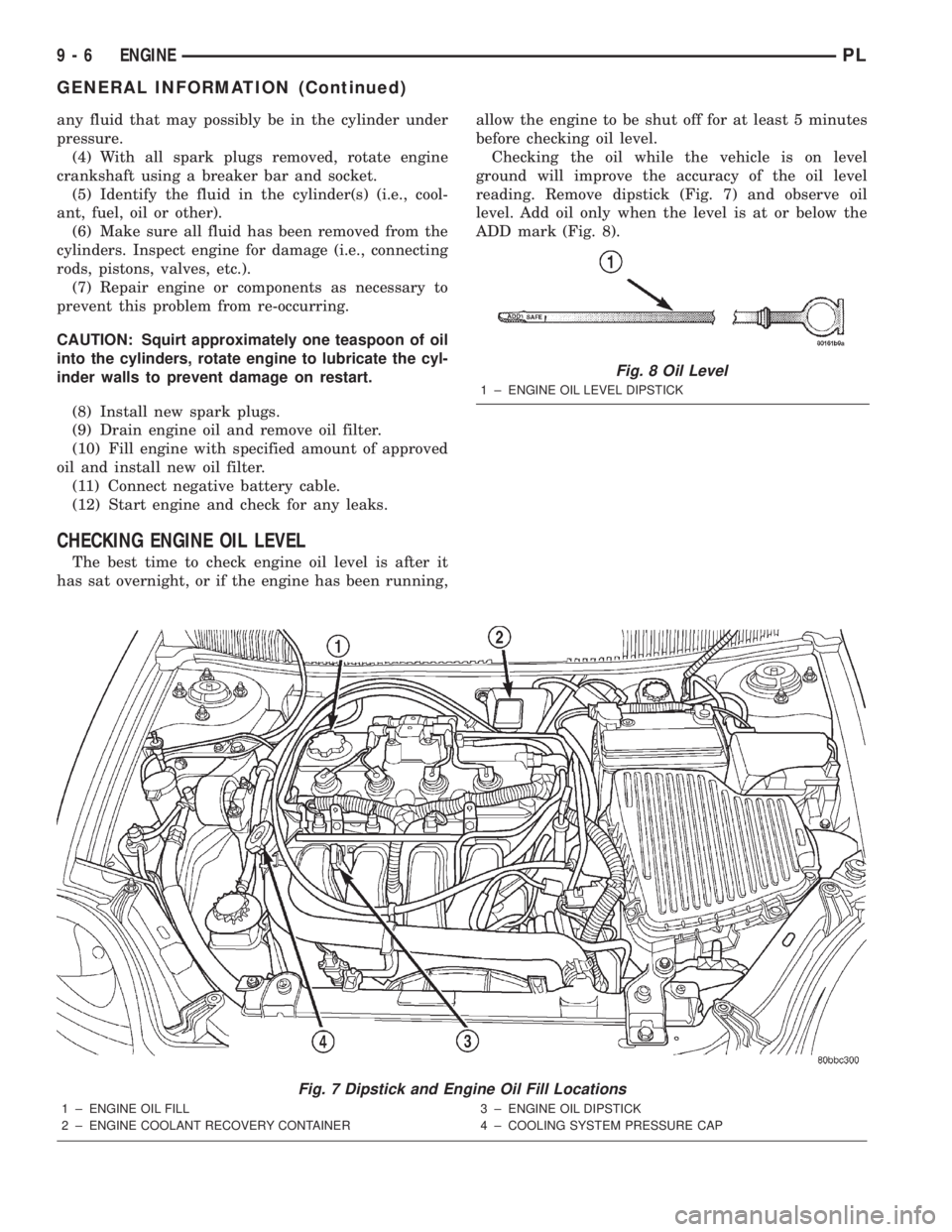
reading. Remove dipstick (Fig. 7) and observe oil
level. Add oil only when the level is at or below the
ADD mark (Fig. 8).
Fig. 7 Dipstick and Engine Oil Fill Locations
1 ± ENGINE OIL FILL
2 ± ENGINE COOLANT RECOVERY CONTAINER3 ± ENGINE OIL DIPSTICK
4 ± COOLING SYSTEM PRESSURE CAP
Fig. 8 Oil Level
1 ± ENGINE OIL LEVEL DIPSTICK
9 - 6 ENGINEPL
GENERAL INFORMATION (Continued)