2000 DODGE NEON air leak
[x] Cancel search: air leakPage 9 of 1285
onds, stop cranking engine and allow starter to cool
(15 minutes), before cranking again.
DISCONNECT CABLE CLAMPS AS FOLLOWS:
²Disconnect BLACK cable clamp from engine
ground on disabled vehicle.
²When using a Booster vehicle, disconnect
BLACK cable clamp from battery negative terminal.
Disconnect RED cable clamp from battery positive
terminal.
²Disconnect RED cable clamp from battery posi-
tive terminal on disabled vehicle.
TOWING RECOMMENDATIONS
WARNING: DO NOT ALLOW TOWING ATTACHMENT
DEVICES TO CONTACT THE FUEL TANK OR LINES,
FUEL LEAK CAN RESULT. DO NOT LIFT OR TOW
VEHICLE BY FRONT OR REAR BUMPER, OR
BUMPER ENERGY ABSORBER UNITS. DO NOT
VENTURE UNDER A LIFTED VEHICLE IF NOT SUP-
PORTED PROPERLY ON SAFETY STANDS. DO NOT
ALLOW PASSENGERS TO RIDE IN A TOWED VEHI-
CLE. USE A SAFETY CHAIN THAT IS INDEPENDENT
FROM THE TOWING ATTACHMENT DEVICE.
CAUTION: Do not damage brake lines, exhaust sys-
tem, shock absorbers, sway bars, or any other
under vehicle components when attaching towing
device to vehicle. Do not attach towing device to
front or rear suspension components. Do notsecure vehicle to towing device by the use of front
or rear suspension or steering components.
Remove or secure loose or protruding objects from
a damaged vehicle before towing. Refer to state and
local rules and regulations before towing a vehicle.
Do not allow weight of towed vehicle to bear on
lower fascia, air dams, or spoilers.
RECOMMENDED TOWING EQUIPMENT
To avoid damage to bumper fascia and air dams
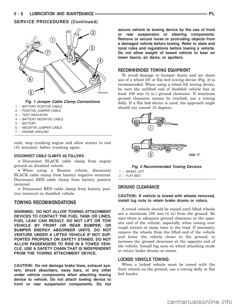
use of a wheel lift or flat bed towing device (Fig. 2) is
recommended. When using a wheel lift towing device,
be sure the unlifted end of disabled vehicle has at
least 100 mm (4 in.) ground clearance. If minimum
ground clearance cannot be reached, use a towing
dolly. If a flat bed device is used, the approach angle
should not exceed 15 degrees.
GROUND CLEARANCE
CAUTION: If vehicle is towed with wheels removed,
install lug nuts to retain brake drums or rotors.
A towed vehicle should be raised until lifted wheels
are a minimum 100 mm (4 in) from the ground. Be
sure there is adequate ground clearance at the oppo-
site end of the vehicle, especially when towing over
rough terrain or steep rises in the road. If necessary,
remove the wheels from the lifted end of the vehicle
and lower the vehicle closer to the ground, to
increase the ground clearance at the opposite end of
the vehicle. Install lug nuts on wheel attaching studs
to retain brake drums or rotors.
LOCKED VEHICLE TOWING
When a locked vehicle must be towed with the
front wheels on the ground, use a towing dolly or flat
bed hauler.
Fig. 1 Jumper Cable Clamp Connections
1 ± BATTERY POSITIVE CABLE
2 ± POSITIVE JUMPER CABLE
3 ± TEST INDICATOR
4 ± BATTERY NEGATIVE CABLE
5 ± BATTERY
6 ± NEGATIVE JUMPER CABLE
7 ± ENGINE GROUND
Fig. 2 Recommended Towing Devices
1 ± WHEEL LIFT
2 ± FLAT BED
0 - 8 LUBRICATION AND MAINTENANCEPL
SERVICE PROCEDURES (Continued)
Page 88 of 1285
DIAGNOSIS AND TESTING
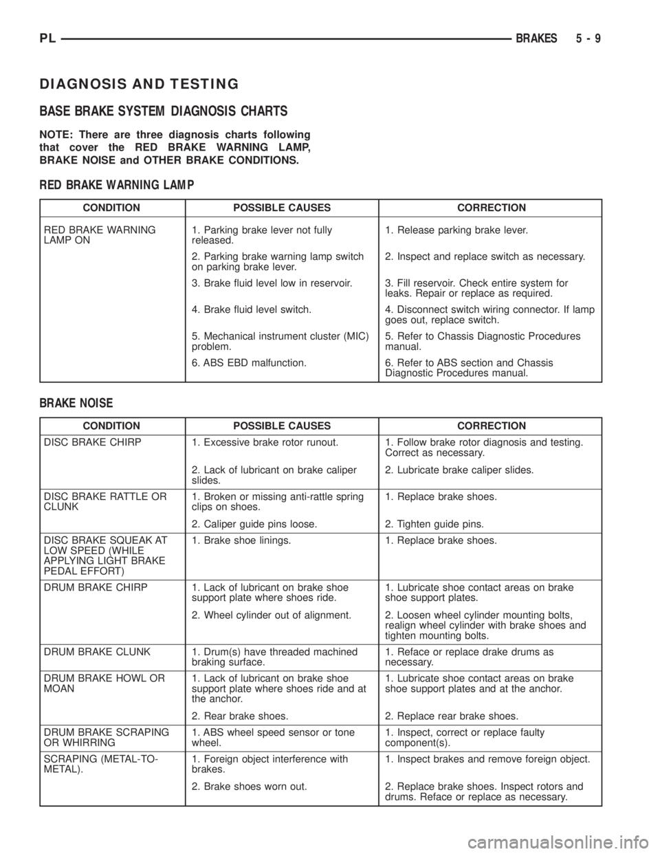
BASE BRAKE SYSTEM DIAGNOSIS CHARTS
NOTE: There are three diagnosis charts following
that cover the RED BRAKE WARNING LAMP,
BRAKE NOISE and OTHER BRAKE CONDITIONS.
RED BRAKE WARNING LAMP
CONDITION POSSIBLE CAUSES CORRECTION
RED BRAKE WARNING
LAMP ON1. Parking brake lever not fully
released.1. Release parking brake lever.
2. Parking brake warning lamp switch
on parking brake lever.2. Inspect and replace switch as necessary.
3. Brake fluid level low in reservoir. 3. Fill reservoir. Check entire system for
leaks. Repair or replace as required.
4. Brake fluid level switch. 4. Disconnect switch wiring connector. If lamp
goes out, replace switch.
5. Mechanical instrument cluster (MIC)
problem.5. Refer to Chassis Diagnostic Procedures
manual.
6. ABS EBD malfunction. 6. Refer to ABS section and Chassis
Diagnostic Procedures manual.
BRAKE NOISE
CONDITION POSSIBLE CAUSES CORRECTION
DISC BRAKE CHIRP 1. Excessive brake rotor runout. 1. Follow brake rotor diagnosis and testing.
Correct as necessary.
2. Lack of lubricant on brake caliper
slides.2. Lubricate brake caliper slides.
DISC BRAKE RATTLE OR
CLUNK1. Broken or missing anti-rattle spring
clips on shoes.1. Replace brake shoes.
2. Caliper guide pins loose. 2. Tighten guide pins.
DISC BRAKE SQUEAK AT
LOW SPEED (WHILE
APPLYING LIGHT BRAKE
PEDAL EFFORT)1. Brake shoe linings. 1. Replace brake shoes.
DRUM BRAKE CHIRP 1. Lack of lubricant on brake shoe
support plate where shoes ride.1. Lubricate shoe contact areas on brake
shoe support plates.
2. Wheel cylinder out of alignment. 2. Loosen wheel cylinder mounting bolts,
realign wheel cylinder with brake shoes and
tighten mounting bolts.
DRUM BRAKE CLUNK 1. Drum(s) have threaded machined
braking surface.1. Reface or replace drake drums as
necessary.
DRUM BRAKE HOWL OR
MOAN1. Lack of lubricant on brake shoe
support plate where shoes ride and at
the anchor.1. Lubricate shoe contact areas on brake
shoe support plates and at the anchor.
2. Rear brake shoes. 2. Replace rear brake shoes.
DRUM BRAKE SCRAPING
OR WHIRRING1. ABS wheel speed sensor or tone
wheel.1. Inspect, correct or replace faulty
component(s).
SCRAPING (METAL-TO-
METAL).1. Foreign object interference with
brakes.1. Inspect brakes and remove foreign object.
2. Brake shoes worn out. 2. Replace brake shoes. Inspect rotors and
drums. Reface or replace as necessary.
PLBRAKES 5 - 9
Page 89 of 1285
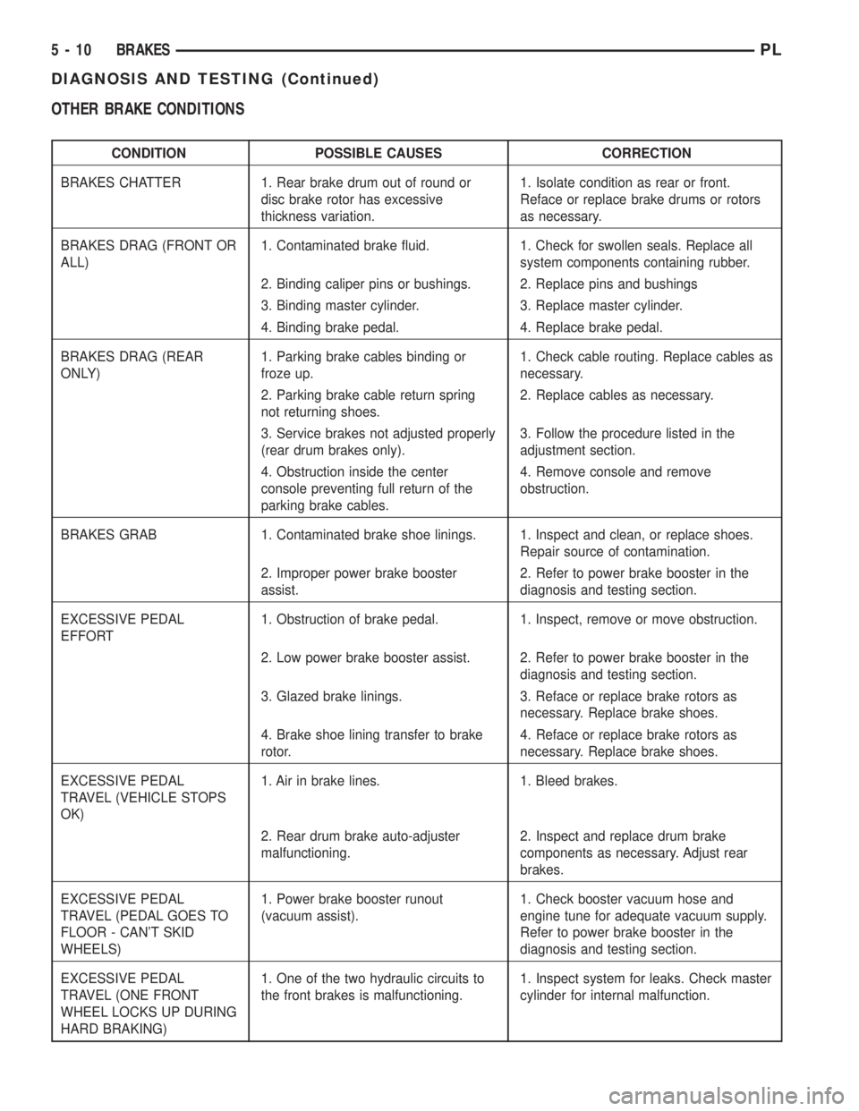
OTHER BRAKE CONDITIONS
CONDITION POSSIBLE CAUSES CORRECTION
BRAKES CHATTER 1. Rear brake drum out of round or
disc brake rotor has excessive
thickness variation.1. Isolate condition as rear or front.
Reface or replace brake drums or rotors
as necessary.
BRAKES DRAG (FRONT OR
ALL)1. Contaminated brake fluid. 1. Check for swollen seals. Replace all
system components containing rubber.
2. Binding caliper pins or bushings. 2. Replace pins and bushings
3. Binding master cylinder. 3. Replace master cylinder.
4. Binding brake pedal. 4. Replace brake pedal.
BRAKES DRAG (REAR
ONLY)1. Parking brake cables binding or
froze up.1. Check cable routing. Replace cables as
necessary.
2. Parking brake cable return spring
not returning shoes.2. Replace cables as necessary.
3. Service brakes not adjusted properly
(rear drum brakes only).3. Follow the procedure listed in the
adjustment section.
4. Obstruction inside the center
console preventing full return of the
parking brake cables.4. Remove console and remove
obstruction.
BRAKES GRAB 1. Contaminated brake shoe linings. 1. Inspect and clean, or replace shoes.
Repair source of contamination.
2. Improper power brake booster
assist.2. Refer to power brake booster in the
diagnosis and testing section.
EXCESSIVE PEDAL
EFFORT1. Obstruction of brake pedal. 1. Inspect, remove or move obstruction.
2. Low power brake booster assist. 2. Refer to power brake booster in the
diagnosis and testing section.
3. Glazed brake linings. 3. Reface or replace brake rotors as
necessary. Replace brake shoes.
4. Brake shoe lining transfer to brake
rotor.4. Reface or replace brake rotors as
necessary. Replace brake shoes.
EXCESSIVE PEDAL
TRAVEL (VEHICLE STOPS
OK)1. Air in brake lines. 1. Bleed brakes.
2. Rear drum brake auto-adjuster
malfunctioning.2. Inspect and replace drum brake
components as necessary. Adjust rear
brakes.
EXCESSIVE PEDAL
TRAVEL (PEDAL GOES TO
FLOOR - CAN'T SKID
WHEELS)1. Power brake booster runout
(vacuum assist).1. Check booster vacuum hose and
engine tune for adequate vacuum supply.
Refer to power brake booster in the
diagnosis and testing section.
EXCESSIVE PEDAL
TRAVEL (ONE FRONT
WHEEL LOCKS UP DURING
HARD BRAKING)1. One of the two hydraulic circuits to
the front brakes is malfunctioning.1. Inspect system for leaks. Check master
cylinder for internal malfunction.
5 - 10 BRAKESPL
DIAGNOSIS AND TESTING (Continued)
Page 90 of 1285
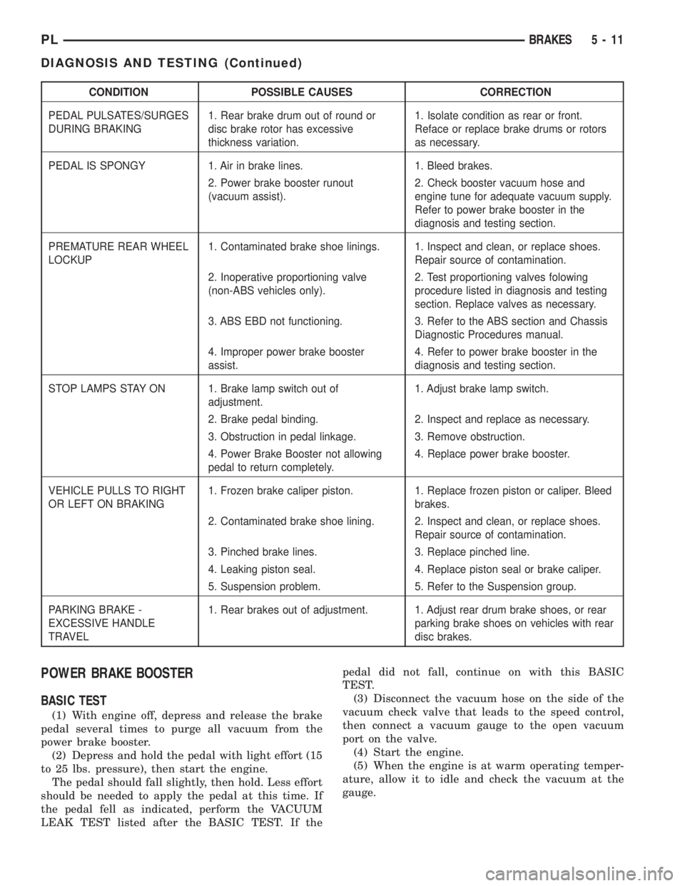
CONDITION POSSIBLE CAUSES CORRECTION
PEDAL PULSATES/SURGES
DURING BRAKING1. Rear brake drum out of round or
disc brake rotor has excessive
thickness variation.1. Isolate condition as rear or front.
Reface or replace brake drums or rotors
as necessary.
PEDAL IS SPONGY 1. Air in brake lines. 1. Bleed brakes.
2. Power brake booster runout
(vacuum assist).2. Check booster vacuum hose and
engine tune for adequate vacuum supply.
Refer to power brake booster in the
diagnosis and testing section.
PREMATURE REAR WHEEL
LOCKUP1. Contaminated brake shoe linings. 1. Inspect and clean, or replace shoes.
Repair source of contamination.
2. Inoperative proportioning valve
(non-ABS vehicles only).2. Test proportioning valves folowing
procedure listed in diagnosis and testing
section. Replace valves as necessary.
3. ABS EBD not functioning. 3. Refer to the ABS section and Chassis
Diagnostic Procedures manual.
4. Improper power brake booster
assist.4. Refer to power brake booster in the
diagnosis and testing section.
STOP LAMPS STAY ON 1. Brake lamp switch out of
adjustment.1. Adjust brake lamp switch.
2. Brake pedal binding. 2. Inspect and replace as necessary.
3. Obstruction in pedal linkage. 3. Remove obstruction.
4. Power Brake Booster not allowing
pedal to return completely.4. Replace power brake booster.
VEHICLE PULLS TO RIGHT
OR LEFT ON BRAKING1. Frozen brake caliper piston. 1. Replace frozen piston or caliper. Bleed
brakes.
2. Contaminated brake shoe lining. 2. Inspect and clean, or replace shoes.
Repair source of contamination.
3. Pinched brake lines. 3. Replace pinched line.
4. Leaking piston seal. 4. Replace piston seal or brake caliper.
5. Suspension problem. 5. Refer to the Suspension group.
PARKING BRAKE -
EXCESSIVE HANDLE
TRAVEL1. Rear brakes out of adjustment. 1. Adjust rear drum brake shoes, or rear
parking brake shoes on vehicles with rear
disc brakes.
POWER BRAKE BOOSTER
BASIC TEST
(1) With engine off, depress and release the brake
pedal several times to purge all vacuum from the
power brake booster.
(2) Depress and hold the pedal with light effort (15
to 25 lbs. pressure), then start the engine.
The pedal should fall slightly, then hold. Less effort
should be needed to apply the pedal at this time. If
the pedal fell as indicated, perform the VACUUM
LEAK TEST listed after the BASIC TEST. If thepedal did not fall, continue on with this BASIC
TEST.
(3) Disconnect the vacuum hose on the side of the
vacuum check valve that leads to the speed control,
then connect a vacuum gauge to the open vacuum
port on the valve.
(4) Start the engine.
(5) When the engine is at warm operating temper-
ature, allow it to idle and check the vacuum at the
gauge.
PLBRAKES 5 - 11
DIAGNOSIS AND TESTING (Continued)
Page 91 of 1285
If the vacuum supply is 12 inches Hg (40.5 kPa) or
more, the power brake booster is defective and must
be replaced. If the vacuum supply is below 12 inches,
continue on with this BASIC TEST.
(6) Shut off the engine.
(7) Connect the vacuum gauge to the vacuum ref-
erence port on the engine intake manifold.
(8)
Start the engine and observe the vacuum gauge.
If the vacuum is still low, check the engine tune
and repair as necessary. If the vacuum is above 12
inches, the hose or check to the booster has a restric-
tion or leak.
Once an adequate vacuum supply is obtained,
repeat the BASIC TEST.
VACUUM LEAK TEST
(1) Disconnect the vacuum hose on the side of the
power brake booster vacuum check valve that leads
to the speed control, then connect a vacuum gauge to
the open vacuum port on the valve.
(2) Remove the remaining hose on the vacuum
check valve that is not the vacuum supply hose com-
ing from the intake manifold. Cap off the open port
on the check valve.
(3) Start the engine.
(4) Allow the engine to warm up to normal operat-
ing temperature and engine idle.
(5) Using vacuum line pliers, close off the vacuum
supply hose near the booster and observe the vacuum
gauge.
If the vacuum drop exceeds 1.0 inch Hg (3.3 kPa)
in one minute, repeat the above steps to confirm the
reading. The vacuum loss should be less than 1.0
inch Hg in one minute time span. If the loss is more
than 1.0 inch Hg, replace the power brake booster. If
it is not, continue on with this test.
(6) Remove the pliers from the hose temporarily.
(7) Apply light effort (approximately 15 lbs. of
force) to the brake pedal and hold the pedal steady.
Do not move the pedal once the pressure is applied
or the test results may vary.
(8) Have an assistant reattach the pliers to the
vacuum supply hose.
(9) Allow 5 seconds for stabilization, then observe
the vacuum gauge.
If the vacuum drop exceeds 3.0 inches Hg (10 kPa)
in 15 seconds, repeat the above steps to confirm the
reading. The vacuum loss should be less than 3.0
inches Hg in 15 seconds time span. If the loss is
more than 3.0 inches Hg, replace the power brake
booster. If it is not, the booster is not defective.
DRUM BRAKE AUTOMATIC ADJUSTER
To properly test the drum brake automatic
adjuster, the aide of a helper inside the vehicle to
apply the brakes will be necessary.(1) Raise the vehicle. Refer to HOISTING in the
LUBRICATION AND MAINTENANCE group for the
proper lifting procedure.
(2) Remove the access plug from the rear adjust-
ment slot in each brake support plate.
(3) Insert a thin screwdriver in the adjustment
slot and push back the adjustment lever. With the
lever in this position, back the star wheel adjustment
off approximately 10 notches. This will eliminate the
possibility that the brake is at full adjustment, and
can be adjusted no further.
(4)
Remove the screwdriver from the adjustment slot.
(5) Watch the star wheel through the adjustment
slot, while a helper applies the brake pedal. As the
brake shoes apply, the adjustment lever should move
downward, turning the star wheel. A definite rotation
of the adjuster star wheel can be observed if the
automatic adjuster is working properly.
If the star wheel does not move as indicated, the
brake drum needs to be removed and further inspec-
tion of the rear brakes is necessary.
(6) If the star wheel is operating properly, readjust
the brakes. Refer to ADJUSTMENTS in this section
of this service manual group.
(7) Reinstall the adjustment slot access plug.
(8) Lower the vehicle.
BRAKE ROTOR
Any servicing of the rotor requires extreme care to
maintain the rotor within service tolerances to
ensure proper brake action.
Excessive runout or wobble in a rotor can increase
pedal travel due to piston knock-back. This increases
guide pin sleeve wear due to the tendency of the cal-
iper to follow the rotor wobble.
When diagnosing a brake noise or pulsation, the
machined disc braking surface should be checked and
inspected.
BRAKING SURFACE INSPECTION
Light braking surface scoring and wear is accept-
able. If heavy scoring or warping is evident, the rotor
must be refaced or replaced. Refer to SERVICE PRO-
CEDURES in this section of this group for informa-
tion on brake rotor machining.
Excessive wear and scoring of the rotor can cause
improper lining contact on the rotor's braking sur-
face. If the ridges on the rotor are not removed before
new brake shoes are installed, improper wear of the
shoes will result.
If a vehicle has not been driven for a period of
time, the rotor's braking surface will rust in the
areas not covered by the brake shoes at that time.
Once the vehicle is driven, noise and chatter from
the disc brakes can result when the brakes are
applied.
5 - 12 BRAKESPL
DIAGNOSIS AND TESTING (Continued)
Page 176 of 1285
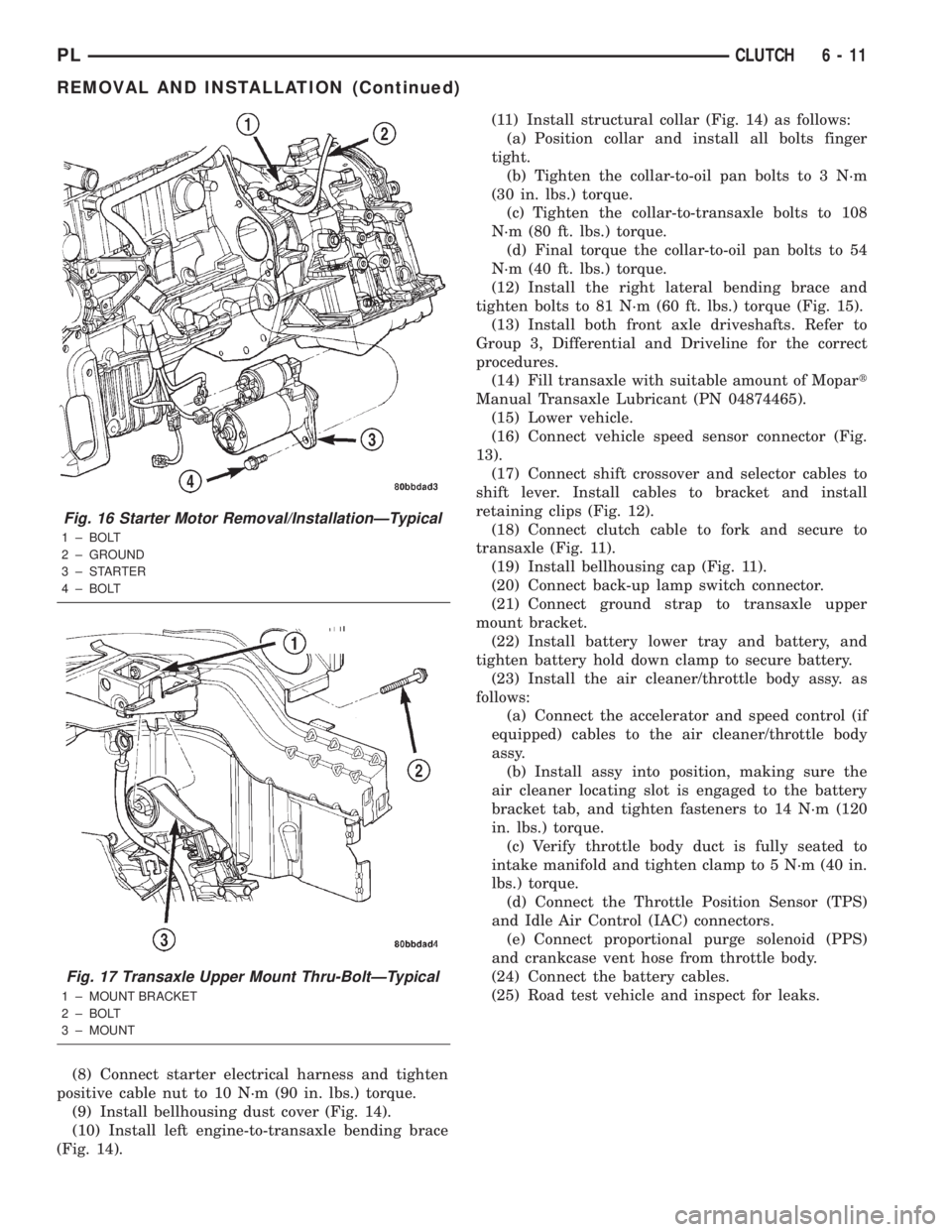
(8) Connect starter electrical harness and tighten
positive cable nut to 10 N´m (90 in. lbs.) torque.
(9) Install bellhousing dust cover (Fig. 14).
(10) Install left engine-to-transaxle bending brace
(Fig. 14).(11) Install structural collar (Fig. 14) as follows:
(a) Position collar and install all bolts finger
tight.
(b) Tighten the collar-to-oil pan bolts to 3 N´m
(30 in. lbs.) torque.
(c) Tighten the collar-to-transaxle bolts to 108
N´m (80 ft. lbs.) torque.
(d) Final torque the collar-to-oil pan bolts to 54
N´m (40 ft. lbs.) torque.
(12) Install the right lateral bending brace and
tighten bolts to 81 N´m (60 ft. lbs.) torque (Fig. 15).
(13) Install both front axle driveshafts. Refer to
Group 3, Differential and Driveline for the correct
procedures.
(14) Fill transaxle with suitable amount of Mopart
Manual Transaxle Lubricant (PN 04874465).
(15) Lower vehicle.
(16) Connect vehicle speed sensor connector (Fig.
13).
(17) Connect shift crossover and selector cables to
shift lever. Install cables to bracket and install
retaining clips (Fig. 12).
(18) Connect clutch cable to fork and secure to
transaxle (Fig. 11).
(19) Install bellhousing cap (Fig. 11).
(20) Connect back-up lamp switch connector.
(21) Connect ground strap to transaxle upper
mount bracket.
(22) Install battery lower tray and battery, and
tighten battery hold down clamp to secure battery.
(23) Install the air cleaner/throttle body assy. as
follows:
(a) Connect the accelerator and speed control (if
equipped) cables to the air cleaner/throttle body
assy.
(b) Install assy into position, making sure the
air cleaner locating slot is engaged to the battery
bracket tab, and tighten fasteners to 14 N´m (120
in. lbs.) torque.
(c) Verify throttle body duct is fully seated to
intake manifold and tighten clamp to 5 N´m (40 in.
lbs.) torque.
(d) Connect the Throttle Position Sensor (TPS)
and Idle Air Control (IAC) connectors.
(e) Connect proportional purge solenoid (PPS)
and crankcase vent hose from throttle body.
(24) Connect the battery cables.
(25) Road test vehicle and inspect for leaks.
Fig. 16 Starter Motor Removal/InstallationÐTypical
1 ± BOLT
2 ± GROUND
3±STARTER
4 ± BOLT
Fig. 17 Transaxle Upper Mount Thru-BoltÐTypical
1 ± MOUNT BRACKET
2 ± BOLT
3 ± MOUNT
PLCLUTCH 6 - 11
REMOVAL AND INSTALLATION (Continued)
Page 180 of 1285
COOLING SYSTEM
TABLE OF CONTENTS
page page
DESCRIPTION AND OPERATION
COOLING SYSTEM........................1
COOLANT...............................2
COOLANT PERFORMANCE..................2
COOLANT RECOVERY SYSTEM..............3
ENGINE THERMOSTAT.....................3
RADIATOR..............................3
RADIATOR COOLING FAN MODULE...........3
COOLING SYSTEM PRESSURE CAP..........4
RADIATOR HOSES AND CLAMPS............5
WATER PUMP...........................5
AUTOMATIC TRANSMISSION OIL COOLER.....6
ACCESSORY DRIVE BELTS.................6
ENGINE BLOCK HEATER...................6
DIAGNOSIS AND TESTING
COOLING SYSTEM DIAGNOSIS..............7
ENGINE THERMOSTAT TESTING............14
ACCESSORY DRIVE BELT DIAGNOSIS........14
WATER PUMP DIAGNOSIS................15
COOLING SYSTEM FLOW CHECK...........15
ELECTRIC FAN MOTOR TEST...............15
COOLANT CONCENTRATION TESTING........15
TESTING COOLING SYSTEM FOR LEAKS.....15
PRESSURE CAP TO FILLER NECK SEAL
PRESSURE RELIEF CHECK...............16
PRESSURE TESTING COOLING SYSTEM
PRESSURE CAP.......................16
LOW COOLANT LEVEL AERATION...........17
DEAERATION...........................17
TEMPERATURE GAUGE INDICATION.........17
ENGINE BLOCK HEATER..................17
SERVICE PROCEDURES
COOLANT LEVEL CHECKÐROUTINE.........17COOLANTÐADDING ADDITIONAL...........18
COOLANT LEVELÐSERVICING.............18
COOLING SYSTEMÐDRAINING.............19
COOLING SYSTEMÐREFILLING............19
REMOVAL AND INSTALLATION
WATER PUMP..........................19
WATER PUMP INLET TUBE................20
ENGINE THERMOSTAT....................20
RADIATOR.............................21
RADIATOR DRAINCOCK...................22
COOLING FAN MODULE...................22
COOLANT RECOVERY CONTAINER..........23
ENGINE BLOCK HEATER..................24
ACCESSORY DRIVE BELTS................24
AUTOMATIC BELT TENSIONER & PULLEY....26
DISASSEMBLY AND ASSEMBLY
COOLING FAN MODULE...................26
CLEANING AND INSPECTION
WATER PUMP..........................28
ACCESSORY DRIVE BELT INSPECTION.......28
COOLING SYSTEM CAP...................28
COOLING SYSTEM CLEANING..............28
RADIATOR FLUSHING....................28
REVERSE FLUSHING.....................29
CHEMICAL CLEANING....................29
ADJUSTMENTS
BELT TENSION..........................29
SPECIFICATIONS
COOLING SYSTEM CAPACITY..............30
TORQUE SPECIFICATIONS.................30
SPECIAL TOOLS
COOLING..............................30
DESCRIPTION AND OPERATION
COOLING SYSTEM
The cooling system consists of an engine cooling
module, thermostat, coolant, and a water pump to
circulate the coolant. The engine cooling module may
consist of a radiator, electric fan motor, fan, shroud,
coolant reserve system, transmission oil cooler, hoses,clamps, air conditioning condenser and transmission
oil lines.
²When the Engine is cold: The thermostat is
closed and the cooling system has no flow through
the radiator. The coolant flows through the engine,
heater system and bypass.
²When the Engine is warm: Thermostat is open
and the cooling system has flow through the radiator,
engine, heater system, and bypass.
PLCOOLING SYSTEM 7 - 1
Page 182 of 1285
protection. MopartAntifreeze or the equivalent is
recommended for best engine cooling without corro-
sion. When mixed only to a freeze point of -37ÉC
(-35ÉF) to -59ÉC (-50ÉF). If it looses color or becomes
contaminated, drain, flush, and replace with fresh
properly mixed solution.
COOLANT RECOVERY SYSTEM
This system works in conjunction with the radiator
pressure cap to utilize thermal expansion and con-
traction of the coolant to keep the coolant free of
trapped air. The system provides space for expansion
and contraction. Also, the system provides a conve-
nient and safe method for checking and adjusting the
coolant level at atmospheric pressure without remov-
ing the pressure cap. It also provides some reserve
coolant to compensate for minor leaks and evapora-
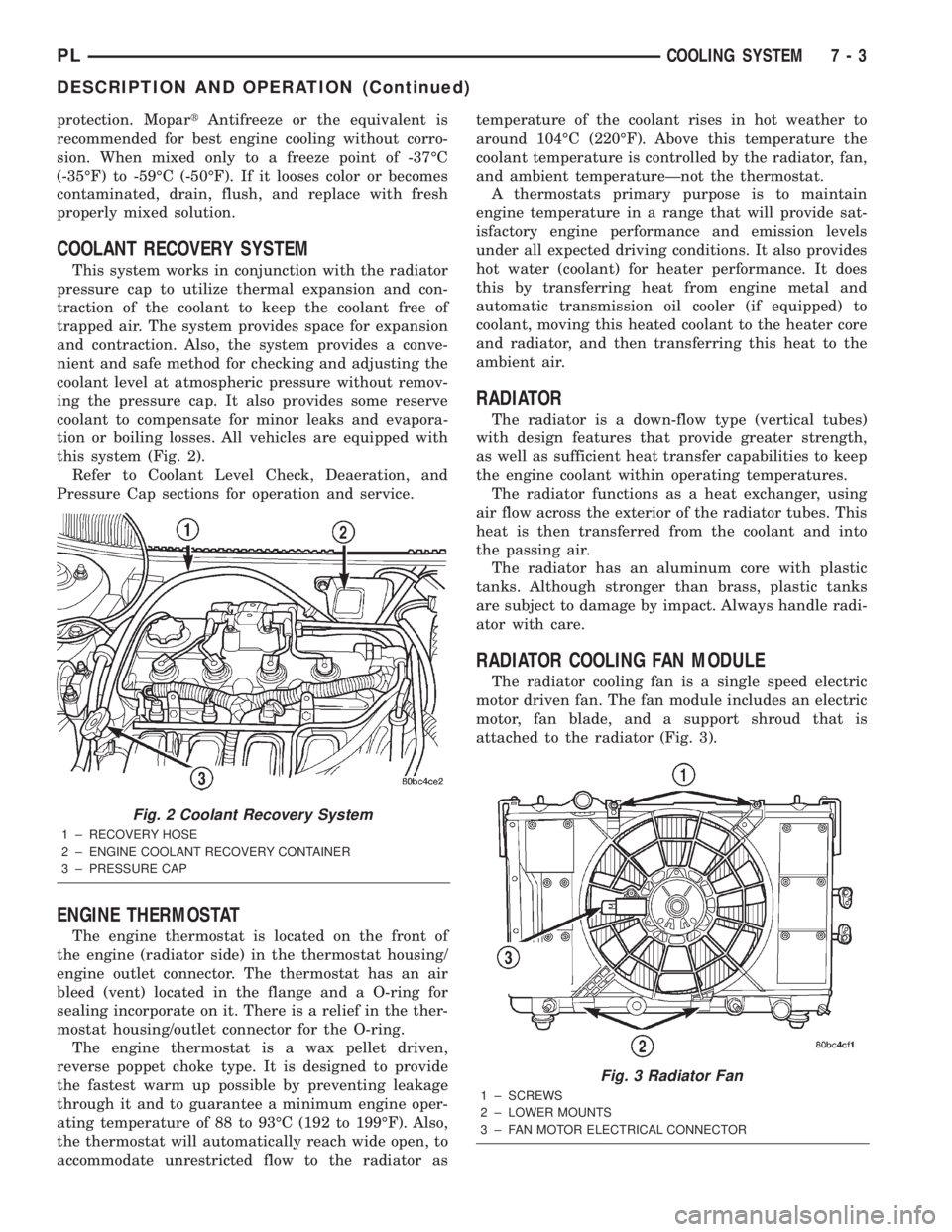
tion or boiling losses. All vehicles are equipped with
this system (Fig. 2).
Refer to Coolant Level Check, Deaeration, and
Pressure Cap sections for operation and service.
ENGINE THERMOSTAT
The engine thermostat is located on the front of
the engine (radiator side) in the thermostat housing/
engine outlet connector. The thermostat has an air
bleed (vent) located in the flange and a O-ring for
sealing incorporate on it. There is a relief in the ther-
mostat housing/outlet connector for the O-ring.
The engine thermostat is a wax pellet driven,
reverse poppet choke type. It is designed to provide
the fastest warm up possible by preventing leakage
through it and to guarantee a minimum engine oper-
ating temperature of 88 to 93ÉC (192 to 199ÉF). Also,
the thermostat will automatically reach wide open, to
accommodate unrestricted flow to the radiator astemperature of the coolant rises in hot weather to
around 104ÉC (220ÉF). Above this temperature the
coolant temperature is controlled by the radiator, fan,
and ambient temperatureÐnot the thermostat.
A thermostats primary purpose is to maintain
engine temperature in a range that will provide sat-
isfactory engine performance and emission levels
under all expected driving conditions. It also provides
hot water (coolant) for heater performance. It does
this by transferring heat from engine metal and
automatic transmission oil cooler (if equipped) to
coolant, moving this heated coolant to the heater core
and radiator, and then transferring this heat to the
ambient air.
RADIATOR
The radiator is a down-flow type (vertical tubes)
with design features that provide greater strength,
as well as sufficient heat transfer capabilities to keep
the engine coolant within operating temperatures.
The radiator functions as a heat exchanger, using
air flow across the exterior of the radiator tubes. This
heat is then transferred from the coolant and into
the passing air.
The radiator has an aluminum core with plastic
tanks. Although stronger than brass, plastic tanks
are subject to damage by impact. Always handle radi-
ator with care.
RADIATOR COOLING FAN MODULE
The radiator cooling fan is a single speed electric
motor driven fan. The fan module includes an electric
motor, fan blade, and a support shroud that is
attached to the radiator (Fig. 3).
Fig. 2 Coolant Recovery System
1 ± RECOVERY HOSE
2 ± ENGINE COOLANT RECOVERY CONTAINER
3 ± PRESSURE CAP
Fig. 3 Radiator Fan
1 ± SCREWS
2 ± LOWER MOUNTS
3 ± FAN MOTOR ELECTRICAL CONNECTOR
PLCOOLING SYSTEM 7 - 3
DESCRIPTION AND OPERATION (Continued)