2000 DODGE NEON sensor
[x] Cancel search: sensorPage 822 of 1285
FUEL SYSTEM
TABLE OF CONTENTS
page page
FUEL DELIVERY SYSTEM.................... 1FUEL INJECTION SYSTEM.................. 21
FUEL DELIVERY SYSTEM
TABLE OF CONTENTS
page page
DESCRIPTION AND OPERATION
FUEL REQUIREMENTS.....................1
GASOLINE/OXYGENATE BLENDS.............2
FUEL DELIVERY SYSTEM...................3
FUEL PUMP MODULE......................3
ELECTRIC FUEL PUMP.....................4
FUEL GAUGE SENDING UNIT................4
FUEL FILTER/FUEL PRESSURE REGULATOR....4
FUEL TANK..............................4
FUEL RAIL...............................4
FUEL INJECTORS.........................5
PRESSURE-VACUUM FILLER CAP............5
ONBOARD REFUELING VAPOR RECOVERY....6
CONTROL VALVE/PRESSURE RELIEF.........6
QUICK-CONNECT FITTINGS.................6
ROLLOVER VALVES.......................7
FUEL TUBES/LINES/HOSES AND CLAMPS......8
SERVICE PROCEDURES
FUEL SYSTEM PRESSURE RELEASE
PROCEDURE...........................8INJECTOR CONNECTOR....................8
DRAINING FUEL TANK.....................9
HOSES AND CLAMPS......................9
QUICK-CONNECT FITTINGS.................9
REMOVAL AND INSTALLATION
AUTOMATIC SHUTDOWN RELAY............12
FUEL PUMP RELAY.......................12
FUEL PUMP MODULE.....................12
FUEL FILTER / PRESSURE REGULATOR......13
FUEL PUMP INLET STRAINER..............14
FUEL LEVEL SENSOR.....................14
FUEL INJECTORS........................15
FUEL TANK.............................16
FUEL FILLER NECK.......................17
ACCELERATOR PEDAL....................18
THROTTLE CABLE.......................19
SPECIFICATIONS
TORQUE...............................20
DESCRIPTION AND OPERATION
FUEL REQUIREMENTS
OPERATION
Your engine is designed to meet all emissions reg-
ulations and provide excellent fuel economy and per-
formance when using high quality unleaded gasoline
having an octane rating of 87. The use of premium
gasoline is not recommended. The use of premium
gasoline will provide no benefit over high quality reg-
ular gasoline, and in some circumstances may result
in poorer performance.
Light spark knock at low engine speeds is not
harmful to your engine. However, continued heavyspark knock at high speeds can cause damage and
immediate service is required. Engine damage result-
ing from operation with a heavy spark knock may
not be covered by the new vehicle warranty.
Poor quality gasoline can cause problems such as
hard starting, stalling and hesitations. If you experi-
ence these symptoms, try another brand of gasoline
before considering service for the vehicle.
The American Automobile Manufacturers Associa-
tion, AAMA, has issued gasoline specifications to
define the minimum fuel properties necessary to
deliver enhanced performance and durability for your
vehicle. DaimlerChrysler Corporation recommends
the use of gasoline that meet the AAMA specifica-
tions if they are available.
PLFUEL SYSTEM 14 - 1
Page 824 of 1285
carbon monoxide emissions. The type and amount of
oxygenate used in the blend is important.
The following are generally used in gasoline
blends:
Ethanol- (Ethyl or Grain Alcohol) properly
blended, is used as a mixture of 10 percent ethanol
and 90 percent gasoline. Gasoline blended with etha-
nol may be used in your vehicle.
MTBE/ETBE- Gasoline and MTBE (Methyl Ter-
tiary Butyl Ether) blends are a mixture of unleaded
gasoline and up to 15 percent MTBE. Gasoline and
ETBE (Ethyl Tertiary Butyl Ether) are blends of gas-
oline and up to 17 percent ETBE. Gasoline blended
with MTBE or ETBE may be used in your vehicle.
Methanol- Methanol (Methyl or Wood Alcohol) is
used in a variety of concentrations blended with
unleaded gasoline. You may encounter fuels contain-
ing 3 percent or more methanol along with other
alcohols called cosolvents.
DO NOT USE GASOLINE CONTAINING
METHANOL.
Use of methanol/gasoline blends may result in
starting and driveability problems and damage criti-
cal fuel system components.
Problems that are the result of using methanol/
gasoline blends are not the responsibility of
DaimlerChrysler Corporation and may not be covered
by the vehicle warranty.
Reformulated Gasoline
Many areas of the country are requiring the use of
cleaner-burning fuel referred to asReformulated
Gasoline. Reformulated gasoline are specially
blended to reduce vehicle emissions and improve air
quality.
DaimlerChrysler Corporation strongly supports the
use of reformulated gasoline whenever available.
Although your vehicle was designed to provide opti-
mum performance and lowest emissions operating on
high quality unleaded gasoline, it will perform
equally well and produce even lower emissions when
operating on reformulated gasoline.
Materials Added to Fuel
Indiscriminate use of fuel system cleaning agents
should be avoided. Many of these materials intended
for gum and varnish removal may contain active sol-
vents of similar ingredients that can be harmful to
fuel system gasket and diaphragm materials.
FUEL DELIVERY SYSTEM
OPERATION
The fuel delivery system consists of: the electric
fuel pump, fuel filter/fuel pressure regulator, fuel
tubes/lines/hoses, fuel rail, fuel injectors, fuel tank,
accelerator pedal and throttle cable.A fuel return system is used on all models (all
engines). Fuel is returned through the fuel pump
module and back into the fuel tank through the fuel
filter/fuel pressure regulator. A separate fuel return
line from the engine to the tank is no longer used
with any engine.
The fuel tank assembly consists of: the fuel tank,
filler tube, fuel gauge sending unit/electric fuel pump
module, a rollover valve(s) and a pressure-vacuum
filler cap.
Also to be considered part of the fuel system is the
evaporation control system or Onboard Refueling
Vapor recovery (ORVR). This is designed to reduce
the emission of fuel vapors into the atmosphere. The
description and function of the Evaporative Control
System is found in the Emission Control Systems
section.
FUEL PUMP MODULE
DESCRIPTION
The fuel pump module is installed in the fuel tank
(Fig. 1).
OPERATION
The fuel pump module contains the following:
²Electric fuel pump
²Fuel pump reservoir
²Inlet strainer
²Fuel filter/pressure regulator
²Fuel gauge sending unit
²Fuel supply line connection
Fig. 1 Fuel Pump Module
1 ± FUEL FILTER/PRESSURE REGULATOR
2 ± FUEL LEVEL SENSOR
3 ± FUEL RESERVOIR
4 ± INLET STRAINER
5 ± FLOAT
PLFUEL SYSTEM 14 - 3
DESCRIPTION AND OPERATION (Continued)
Page 825 of 1285
The inlet strainer, fuel pressure regulator and fuel
level sensor are the only serviceable items. If the fuel
pump requires service, replace the fuel pump module.
ELECTRIC FUEL PUMP
DESCRIPTION
The electric fuel pump is located in and is part of
the fuel pump module. It is a positive displacement,
gerotor type, immersible pump with a permanent
magnet electric motor. The fuel pump module is sus-
pended in fuel in the fuel tank.
OPERATION
The pump draws fuel through a strainer and
pushes it through the motor to the outlet. The pump
contains a check valve. The valve, in the pump out-
let, maintains pump pressure during engine off con-
ditions. The fuel pump relay provides voltage to the
fuel pump. The fuel pump has a maximum dead-
headed pressure output of approximately 880 kPa
(130 psi). The regulator adjusts fuel system pressure
to approximately 338 kPa (49 psi).
FUEL GAUGE SENDING UNIT
DESCRIPTION
The fuel gauge sending unit (fuel level sensor) is
attached to the side of the fuel pump module. The
sending unit consists of a float, an arm, and a vari-
able resistor (track). The resistor track is used to
send electrical signals to the instrument cluster for
fuel gauge operation and are then transmitted to the
engine controller for OBDII emission requirements.
OPERATION
For fuel gauge operation:As fuel level
increases, the float and arm move up. This increases
the sending unit resistance, causing the fuel gauge to
read full. As fuel level decreases, the float and arm
move down. This decreases the sending unit resis-
tance causing the fuel gauge to read empty.
After this fuel level signal is sent to the instru-
ment cluster, the instrument cluster will transmit
the data across the J1850 bus circuit to the PCM.
For OBD II emission requirements:The voltage
signal is sent to the instrument cluster to indicate
fuel level. The cluster transmits the fuel level to the
PCM where it is used to prevent a false setting of
misfire and fuel system monitor trouble codes. This
occurs if the fuel level in the tank is less than
approximately 15 percent of its rated capacity.
FUEL FILTER/FUEL PRESSURE REGULATOR
DESCRIPTION
A combination fuel filter and fuel pressure regula-
tor is used on all gas powered engines. It is located
on the top of the fuel pump module. A separate frame
mounted fuel filter is not used.
OPERATION
Fuel Pressure Regulator Operation:The pres-
sure regulator is a mechanical device that is cali-
brated to maintain fuel system operating pressure of
approximately 338 kPa (49 psi) at the fuel injectors.
It contains a diaphragm, calibrated springs and a
fuel return valve. The internal fuel filter (Fig. 2) is
also part of the assembly.
Fuel is supplied to the filter/regulator by the elec-
tric fuel pump through an opening tube at the bot-
tom of filter/regulator.
The fuel pump module contains a check valve to
maintain some fuel pressure when the engine is not
operating. This will help to start the engine.
If fuel pressure at the pressure regulator exceeds
approximately 49 psi, an internal diaphragm closes
and excess fuel pressure is routed back into the tank
through the pressure regulator. A separate fuel
return line is not used with any gas powered engine.
FUEL TANK
OPERATION
All models pass a full 360 degree rollover test
without fuel leakage. To accomplish this, fuel and
vapor flow controls are required for all fuel tank con-
nections.
All models are equipped with either one or two
rollover valves mounted into the top of the fuel tank
(or pump module).
An evaporation control system is connected to the
rollover valve(s) to reduce emissions of fuel vapors
into the atmosphere. When fuel evaporates from the
fuel tank, vapors pass through vent hoses or tubes to
a charcoal canister where they are temporarily held.
When the engine is running, the vapors are drawn
into the intake manifold. Certain models are also
equipped with a self-diagnosing system using a Leak
Detection Pump (LDP). Refer to the Emission Control
System for additional information.
FUEL RAIL
DESCRIPTION
The fuel rail supplies the necessary fuel to each
individual fuel injector and is mounted to the intake
manifold (Fig. 3).
14 - 4 FUEL SYSTEMPL
DESCRIPTION AND OPERATION (Continued)
Page 835 of 1285
FUEL PUMP INLET STRAINER
REMOVAL
(1) Remove fuel pump module. Refer to Fuel Pump
Module Removal in this section.
(2) Using a thin straight blade screwdriver, pry
back the locking tabs on fuel pump reservoir and
remove the strainer (Fig. 18).
(3) Remove strainer O-ring from the fuel pump
reservoir body.
(4) Remove any contaminants in the fuel tank by
washing the inside of the fuel tank.
INSTALLATION
(1) Lubricate the strainer O-ring with clean engine
oil.
(2) Insert strainer O-ring into outlet of strainer so
that it sits evenly on the step inside the outlet.
(3) Push strainer onto the inlet of the fuel pump
reservoir body. Make sure the locking tabs on the
reservoir body lock over the locking tangs on the
strainer.
(4) Install fuel pump module. Refer to Fuel Pump
Module Installation in this section.
FUEL LEVEL SENSOR
REMOVAL
Remove fuel pump module. Refer to Fuel Pump
Module in this section.
(1) Depress retaining tab and remove the fuel
pump/level sensor connector from the bottom of the
fuel pump module electrical connector (Fig. 19).
(2) Pull off blue locking wedge (Fig. 20).
(3) Using a small screwdriver lift locking finger
away from terminal and push terminal out of connec-
tor (Fig. 21).(4) Push level sensor signal and ground terminals
out of the connector (Fig. 22).
(5) Insert a screwdriver between the fuel pump
module and the top of the level sensor housing (Fig.
23). Push level sensor down slightly.
(6) Slide level sensor wires through opening fuel
pump module (Fig. 24).
(7) Slide level sensor out of installation channel in
module.
INSTALLATION
(1) Insert level sensor wires into bottom of opening
in module.
(2) Wrap wires into groove in back of level sensor
(Fig. 23).
Fig. 18 Inlet Strainer Removal
1±TABS
2 ± INLET STRAINER
Fig. 19 Fuel Pump/Level Sensor Electrical
Connector
1 ± RETAINING TAB
2 ± TANK SEAL
3 ± ELECTRICAL CONNECTOR
Fig. 20 Wire Terminal Locking Wedge
1 ± ELECTRICAL CONNECTOR
2 ± BLUE LOCKING WEDGE
14 - 14 FUEL SYSTEMPL
REMOVAL AND INSTALLATION (Continued)
Page 836 of 1285
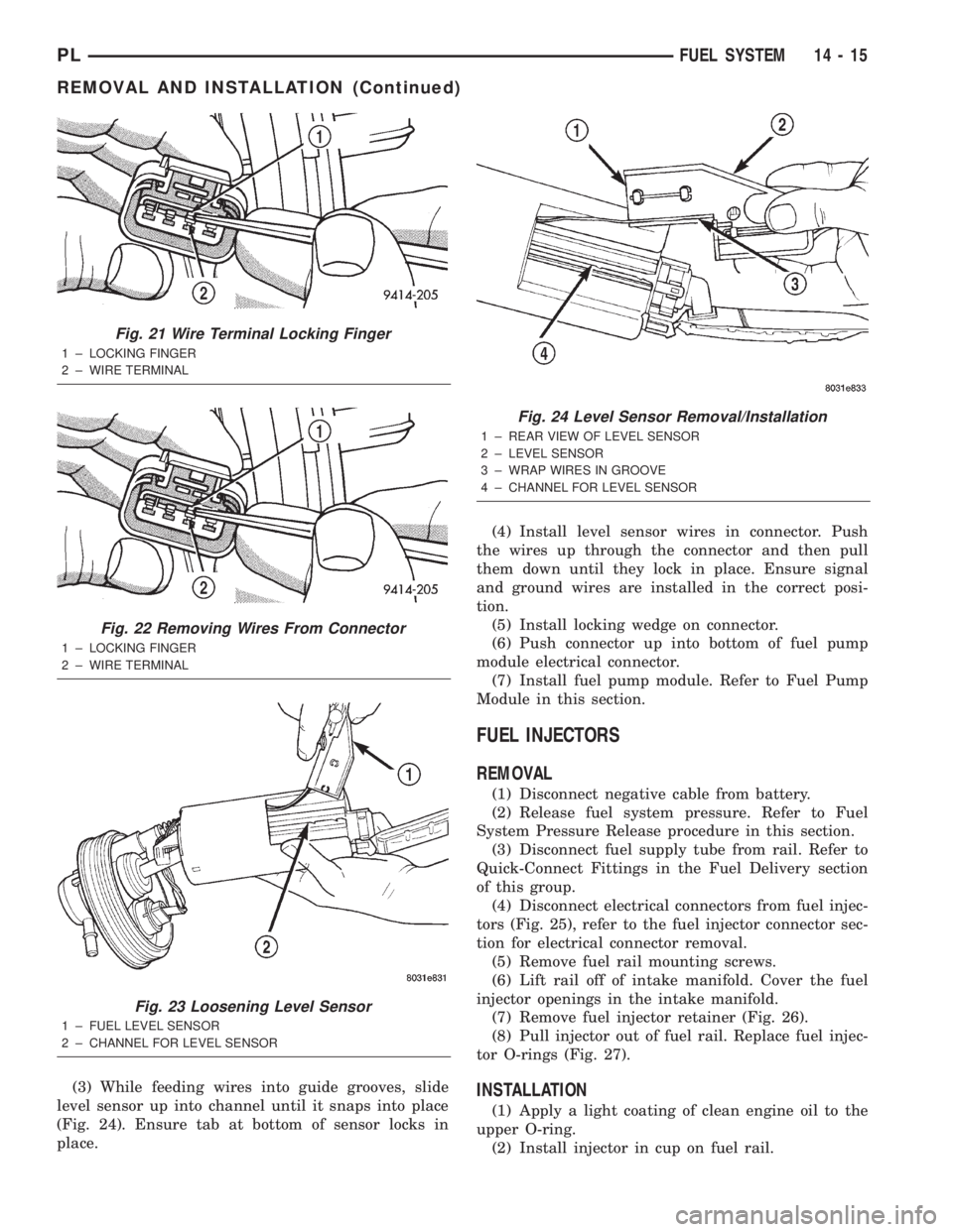
(3) While feeding wires into guide grooves, slide
level sensor up into channel until it snaps into place
(Fig. 24). Ensure tab at bottom of sensor locks in
place.(4) Install level sensor wires in connector. Push
the wires up through the connector and then pull
them down until they lock in place. Ensure signal
and ground wires are installed in the correct posi-
tion.
(5) Install locking wedge on connector.
(6) Push connector up into bottom of fuel pump
module electrical connector.
(7) Install fuel pump module. Refer to Fuel Pump
Module in this section.
FUEL INJECTORS
REMOVAL
(1) Disconnect negative cable from battery.
(2) Release fuel system pressure. Refer to Fuel
System Pressure Release procedure in this section.
(3) Disconnect fuel supply tube from rail. Refer to
Quick-Connect Fittings in the Fuel Delivery section
of this group.
(4) Disconnect electrical connectors from fuel injec-
tors (Fig. 25), refer to the fuel injector connector sec-
tion for electrical connector removal.
(5) Remove fuel rail mounting screws.
(6) Lift rail off of intake manifold. Cover the fuel
injector openings in the intake manifold.
(7) Remove fuel injector retainer (Fig. 26).
(8) Pull injector out of fuel rail. Replace fuel injec-
tor O-rings (Fig. 27).
INSTALLATION
(1) Apply a light coating of clean engine oil to the
upper O-ring.
(2) Install injector in cup on fuel rail.
Fig. 21 Wire Terminal Locking Finger
1 ± LOCKING FINGER
2 ± WIRE TERMINAL
Fig. 22 Removing Wires From Connector
1 ± LOCKING FINGER
2 ± WIRE TERMINAL
Fig. 23 Loosening Level Sensor
1 ± FUEL LEVEL SENSOR
2 ± CHANNEL FOR LEVEL SENSOR
Fig. 24 Level Sensor Removal/Installation
1 ± REAR VIEW OF LEVEL SENSOR
2 ± LEVEL SENSOR
3 ± WRAP WIRES IN GROOVE
4 ± CHANNEL FOR LEVEL SENSOR
PLFUEL SYSTEM 14 - 15
REMOVAL AND INSTALLATION (Continued)
Page 842 of 1285
FUEL INJECTION SYSTEM
TABLE OF CONTENTS
page page
DESCRIPTION AND OPERATION
INJECTION SYSTEM......................22
MODES OF OPERATION...................22
SYSTEM DIAGNOSIS......................24
POWER DISTRIBUTION CENTER............24
POWERTRAIN CONTROL MODULE...........24
PCM GROUND...........................26
5 VOLT SUPPLYÐPCM OUTPUT.............26
8-VOLT SUPPLYÐPCM OUTPUT.............26
FUEL CORRECTION or ADAPTIVE MEMORIES . . 26
PROGRAMMABLE COMMUNICATIONS
INTERFACE (PCI) BUS...................27
AIR CONDITIONING PRESSURE
TRANSDUCERÐPCM INPUT..............27
AUTOMATIC SHUTDOWN (ASD) SENSEÐ
PCM INPUT...........................27
BATTERY VOLTAGEÐPCM INPUT............28
BRAKE SWITCHÐPCM INPUT...............28
CAMSHAFT POSITION SENSORÐPCM INPUT . . 28
CLUTCH INTERLOCK/UPSTOP SWITCH.......29
CRANKSHAFT POSITION SENSORÐPCM
INPUT................................30
ENGINE COOLANT TEMPERATURE
SENSORÐPCM INPUT...................30
FUEL LEVEL SENSORÐPCM INPUT..........31
HEATED OXYGEN SENSOR (O2 SENSOR)Ð
PCM INPUT...........................32
IGNITION CIRCUIT SENSEÐPCM INPUT......34
INLET AIR TEMPERATURE SENSORÐPCM
INPUT................................34
KNOCK SENSORÐPCM INPUT..............34
MANIFOLD ABSOLUTE PRESSURE (MAP)
SENSORÐPCM INPUT...................35
POWER STEERING PRESSURE SWITCHÐ
PCM INPUT...........................35
SENSOR RETURNÐPCM INPUT.............35
SPEED CONTROLÐPCM INPUT.............36
SCI RECEIVEÐPCM INPUT.................36
PARK/NEUTRAL POSITION SWITCHÐPCM
INPUT................................36
THROTTLE POSITION SENSORÐPCM INPUT . . 36VEHICLE SPEED SIGNAL (VSS)ÐPCM INPUT . . 37
AIR CONDITIONING CLUTCH RELAYÐPCM
OUTPUT..............................38
AUTOMATIC SHUTDOWN RELAYÐPCM
OUTPUT..............................38
CHARGING SYSTEM INDICATOR LAMPÐPCM
OUTPUT..............................38
FUEL PUMP RELAYÐPCM OUTPUT..........38
PROPORTIONAL PURGE SOLENOIDÐPCM
OUTPUT..............................39
GENERATOR FIELDÐPCM OUTPUT..........39
IDLE AIR CONTROL MOTORÐPCM OUTPUT . . . 39
DATA LINK CONNECTOR...................40
FUEL INJECTORSÐPCM OUTPUT...........40
IGNITION COILÐPCM OUTPUT..............40
MALFUNCTION INDICATOR (CHECK ENGINE)
LAMPÐPCM OUTPUT...................41
SPEED CONTROLÐPCM INPUT.............41
SCI RECEIVEÐPCM OUTPUT...............41
TACHOMETERÐPCM OUTPUT..............42
TORQUE CONVERTOR CLUTCH SOLENOIDÐ
PCM OUTPUT..........................42
REMOVAL AND INSTALLATION
THROTTLE BODY........................42
THROTTLE POSITION SENSOR.............43
IDLE AIR CONTROL MOTOR................43
MAP SENSOR...........................44
POWERTRAIN CONTROL MODULE (PCM).....44
UPSTREAM HEATED OXYGEN SENSOR......45
DOWNSTREAM HEATED OXYGEN SENSOR
1/2 ..................................46
AIR CLEANER BOX.......................46
AIR CLEANER ELEMENT...................47
ENGINE COOLANT TEMPERATURE SENSOR . . . 47
VEHICLE SPEED SENSOR.................47
KNOCK SENSOR.........................48
SPECIFICATIONS
VECI LABEL.............................49
TORQUE...............................49
SPECIAL TOOLS
FUEL..................................49
PLFUEL SYSTEM 14 - 21
Page 843 of 1285
DESCRIPTION AND OPERATION
INJECTION SYSTEM
All engines used in this section have a sequential
Multi-Port Electronic Fuel Injection system. The MPI
system is computer regulated and provides precise
air/fuel ratios for all driving conditions. The Power-
train Control Module (PCM) operates the fuel injec-
tion system.
The PCM regulates:
²Ignition timing
²Air/fuel ratio
²Emission control devices
²Cooling fan
²Charging system
²Idle speed
²Vehicle speed control
Various sensors provide the inputs necessary for
the PCM to correctly operate these systems. In addi-
tion to the sensors, various switches also provide
inputs to the PCM.
All inputs to the PCM are converted into signals.
The PCM can adapt its programming to meet chang-
ing operating conditions.
Fuel is injected into the intake port above the
intake valve in precise metered amounts through
electrically operated injectors. The PCM fires the
injectors in a specific sequence. Under most operat-
ing conditions, the PCM maintains an air fuel ratio
of 14.7 parts air to 1 part fuel by constantly adjust-
ing injector pulse width. Injector pulse width is the
length of time the injector is open.
The PCM adjusts injector pulse width by opening
and closing the ground path to the injector. Engine
RPM (speed) and manifold absolute pressure (air
density) are the primary inputs that determine injec-
tor pulse width.
MODES OF OPERATION
OPERATION
As input signals to the PCM change, the PCM
adjusts its response to output devices. For example,
the PCM must calculate a different injector pulse
width and ignition timing for idle than it does for
Wide Open Throttle (WOT). There are several differ-
ent modes of operation that determine how the PCM
responds to the various input signals.
There are two different areas of operation, OPEN
LOOP and CLOSED LOOP.
During OPEN LOOP modes the PCM receives
input signals and responds according to preset PCM
programming. Inputs from the upstream and down-
stream heated oxygen sensors are not monitored dur-
ing OPEN LOOP modes, except for heated oxygensensor diagnostics (they are checked for shorted con-
ditions at all times).
During CLOSED LOOP modes the PCM monitors
the inputs from the upstream and downstream
heated oxygen sensors. The upstream heated oxygen
sensor input tells the PCM if the calculated injector
pulse width resulted in the ideal air-fuel ratio of 14.7
to one. By monitoring the exhaust oxygen content
through the upstream heated oxygen sensor, the
PCM can fine tune injector pulse width. Fine tuning
injector pulse width allows the PCM to achieve opti-
mum fuel economy combined with low emissions.
For the PCM to enter CLOSED LOOP operation,
the following must occur:
(1) Engine coolant temperature must be over 35ÉF.
²If the coolant is over 35É the PCM will wait 44
seconds.
²If the coolant is over 50ÉF the PCM will wait 38
seconds.
²If the coolant is over 167ÉF the PCM will wait
11 seconds.
(2) For other temperatures the PCM will interpo-
late the correct waiting time.
(3) O2 sensor must read either greater than 0.745
volts or less than 0.1 volt.
(4) The multi-port fuel injection systems has the
following modes of operation:
²Ignition switch ON (Zero RPM)
²Engine start-up
²Engine warm-up
²Cruise
²Idle
²Acceleration
²Deceleration
²Wide Open Throttle
²Ignition switch OFF
(5) The engine start-up (crank), engine warm-up,
deceleration with fuel shutoff and wide open throttle
modes are OPEN LOOP modes. Under most operat-
ing conditions, the acceleration, deceleration (with
A/C on), idle and cruise modes,with the engine at
operating temperatureare CLOSED LOOP modes.
IGNITION SWITCH ON (ZERO RPM) MODE
When the ignition switch activates the fuel injec-
tion system, the following actions occur:
²The PCM monitors the engine coolant tempera-
ture sensor and throttle position sensor input. The
PCM determines basic fuel injector pulse width from
this input.
²The PCM determines atmospheric air pressure
from the MAP sensor input to modify injector pulse
width.
When the key is in the ON position and the engine
is not running (zero rpm), the Auto Shutdown (ASD)
and fuel pump relays de-energize after approximately
14 - 22 FUEL SYSTEMPL
Page 844 of 1285
1 second. Therefore, battery voltage is not supplied to
the fuel pump, ignition coil, fuel injectors and heated
oxygen sensors.
ENGINE START-UP MODE
This is an OPEN LOOP mode. If the vehicle is in
park or neutral (automatic transaxles) or the clutch
pedal is depressed (manual transaxles) the ignition
switch energizes the starter relay. The following
actions occur when the starter motor is engaged.
²If the PCM receives the camshaft position sensor
and crankshaft position sensor signals, it energizes
the Auto Shutdown (ASD) relay and fuel pump relay.
If the PCM does not receive both signals within
approximately one second, it will not energize the
ASD relay and fuel pump relay. The ASD and fuel
pump relays supply battery voltage to the fuel pump,
fuel injectors, ignition coil and heated oxygen sen-
sors.
²The PCM energizes the injectors (on the 69É
degree falling edge) for a calculated pulse width until
it determines crankshaft position from the camshaft
position sensor and crankshaft position sensor sig-
nals. The PCM determines crankshaft position within
1 engine revolution.
²After determining crankshaft position, the PCM
begins energizing the injectors in sequence. It adjusts
injector pulse width and controls injector synchroni-
zation by turning the individual ground paths to the
injectors On and Off.
²When the engine idles within664 RPM of its
target RPM, the PCM compares current MAP sensor
value with the atmospheric pressure value received
during the Ignition Switch On (zero RPM) mode. If
the PCM does not detect a minimum difference
between the two values, it sets a MAP diagnostic
trouble code into memory.
Once the ASD and fuel pump relays have been
energized, the PCM determines injector pulse width
based on the following:
²Battery voltage
²Engine coolant temperature
²Engine RPM
²Intake air temperature (IAT)
²Throttle position
²The number of engine revolutions since cranking
was initiated.
During Start-up the PCM maintains ignition tim-
ing at 9É BTDC.
ENGINE WARM-UP MODE
This is an OPEN LOOP mode. The following inputs
are received by the PCM:
²Engine coolant temperature
²Manifold Absolute Pressure (MAP)
²Intake air temperature (IAT)²Crankshaft position (engine speed)
²Camshaft position
²Knock sensor
²Throttle position
²A/C switch
²Battery voltage
²Power steering pressure switch
²Vehicle speed
²Speed control
²O2 sensors
²All diagnostics
The PCM adjusts injector pulse width and controls
injector synchronization by turning the individual
ground paths to the injectors On and Off.
The PCM adjusts ignition timing and engine idle
speed. Engine idle speed is adjusted through the idle
air control motor.
CRUISE OR IDLE MODE
When the engine is at operating temperature this
is a CLOSED LOOP mode. During cruising or idle
the following inputs are received by the PCM:
²Intake air temperature
²Engine coolant temperature
²Manifold absolute pressure
²Crankshaft position (engine speed)
²Camshaft position
²Knock sensor
²Throttle position
²Exhaust gas oxygen content
²A/C control positions
²Power steering pressure switch
²Battery voltage
²Vehicle speed
The PCM adjusts injector pulse width and controls
injector synchronization by turning the individual
ground paths to the injectors On and Off.
The PCM adjusts engine idle speed and ignition
timing. The PCM adjusts the air/fuel ratio according
to the oxygen content in the exhaust gas (measured
by the upstream and downstream heated oxygen sen-
sor).
The PCM monitors for engine misfire. During
active misfire and depending on the severity, the
PCM either continuously illuminates or flashes the
malfunction indicator lamp (Check Engine light on
instrument panel). Also, the PCM stores an engine
misfire DTC in memory.
The PCM performs several diagnostic routines.
They include:
²Oxygen sensor monitor
²Downstream heated oxygen sensor diagnostics
during open loop operation (except for shorted)
²Fuel system monitor
²EGR monitor
²Purge system monitor
PLFUEL SYSTEM 14 - 23
DESCRIPTION AND OPERATION (Continued)