2000 DODGE NEON sensor
[x] Cancel search: sensorPage 869 of 1285
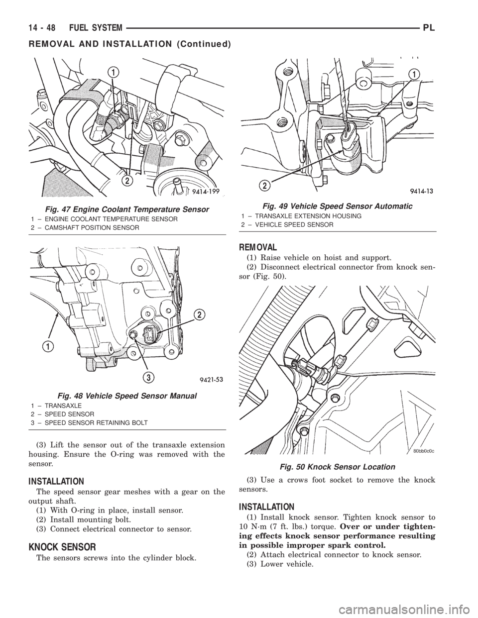
(3) Lift the sensor out of the transaxle extension
housing. Ensure the O-ring was removed with the
sensor.
INSTALLATION
The speed sensor gear meshes with a gear on the
output shaft.
(1) With O-ring in place, install sensor.
(2) Install mounting bolt.
(3) Connect electrical connector to sensor.
KNOCK SENSOR
The sensors screws into the cylinder block.
REMOVAL
(1) Raise vehicle on hoist and support.
(2) Disconnect electrical connector from knock sen-
sor (Fig. 50).
(3) Use a crows foot socket to remove the knock
sensors.
INSTALLATION
(1) Install knock sensor. Tighten knock sensor to
10 N´m (7 ft. lbs.) torque.Over or under tighten-
ing effects knock sensor performance resulting
in possible improper spark control.
(2) Attach electrical connector to knock sensor.
(3) Lower vehicle.
Fig. 47 Engine Coolant Temperature Sensor
1 ± ENGINE COOLANT TEMPERATURE SENSOR
2 ± CAMSHAFT POSITION SENSOR
Fig. 48 Vehicle Speed Sensor Manual
1 ± TRANSAXLE
2 ± SPEED SENSOR
3 ± SPEED SENSOR RETAINING BOLT
Fig. 49 Vehicle Speed Sensor Automatic
1 ± TRANSAXLE EXTENSION HOUSING
2 ± VEHICLE SPEED SENSOR
Fig. 50 Knock Sensor Location
14 - 48 FUEL SYSTEMPL
REMOVAL AND INSTALLATION (Continued)
Page 870 of 1285
SPECIFICATIONS
VECI LABEL
Always use the information found on the Vehicle
Emission Control Information (VECI) label. The
VECI label is located in the engine compartment.
TORQUE
DESCRIPTION TORQUE
Air Cleaner Lid Screws...... 3.9N´m(35in.lbs.)
Crankshaft Position Sensor Mounting Bolts . . 8 N´m
(70 in. lbs.)
Engine Coolant Temperature Sensor...... 18N´m
(165 in. lbs.)
IAC Motor-To-Throttle Body Bolts....... 4.5N´m
(40 in. lbs.)
MAP Sensor............... 4.5N´m(40in.lbs.)
Oxygen Sensor............. 28N´m(20ft.lbs.)
Powertrain Control Module (PCM) Mounting
Screws.................. 4N´m(35in.lbs.)
Throttle Body Mounting Bolts........... 23N´m
(200 in. lbs.)
Throttle Position Sensor Mounting Screws . . 2 N´m
(20 in. lbs.)
Vehicle Speed Sensor Mounting Bolt..... 2.2N´m
(20 in. lbs.)
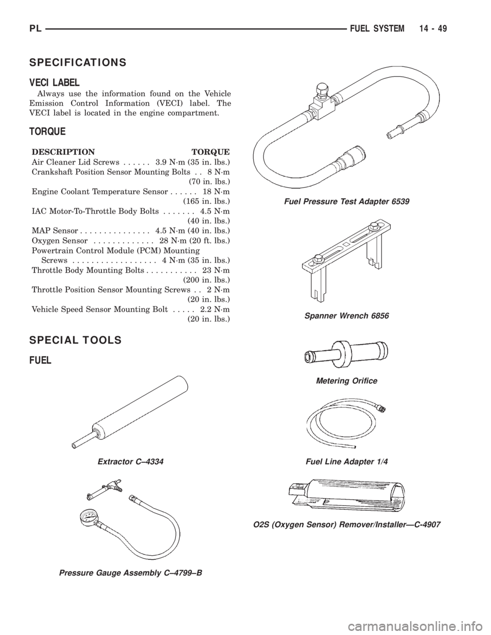
SPECIAL TOOLS
FUEL
Extractor C±4334
Pressure Gauge Assembly C±4799±B
Fuel Pressure Test Adapter 6539
Spanner Wrench 6856
Metering Orifice
Fuel Line Adapter 1/4
O2S (Oxygen Sensor) Remover/InstallerÐC-4907
PLFUEL SYSTEM 14 - 49
Page 914 of 1285
TRANSAXLE
TABLE OF CONTENTS
page page
NV T350 (A-578) MANUAL TRANSAXLE........ 131TH AUTOMATIC TRANSAXLE.............. 54
NV T350 (A-578) MANUAL TRANSAXLE
TABLE OF CONTENTS
page page
GENERAL INFORMATION
NV T350 (A578) MANUAL TRANSAXLE.........1
TRANSAXLE IDENTIFICATION................2
FLUID REQUIREMENTS....................2
SPECIAL ADDITIVES.......................2
SEALANTS..............................2
GEAR RATIOS............................2
GEARSHIFT PATTERN......................3
DIAGNOSIS AND TESTING
COMMON PROBLEM CAUSES...............3
HARD SHIFTING..........................3
NOISY OPERATION........................3
SLIPS OUT OF GEAR......................3
LOW LUBRICANT LEVEL....................4
FLUID LEAKS............................4
CLUTCH PROBLEMS.......................4
SERVICE PROCEDURES
FLUID DRAIN AND FILL.....................4
REMOVAL AND INSTALLATION
GEARSHIFT KNOB........................4
GEARSHIFT BOOT........................5
GEARSHIFT CABLE ASSEMBLY..............6
GEARSHIFT MECHANISM REPLACEMENT......9
VEHICLE SPEED SENSOR AND DRIVE
PINION...............................11
BACK-UP LAMP SWITCH...................12CROSSOVER LEVER......................12
SELECTOR LEVER.......................12
AXLE SHAFT SEALS......................13
SHIFT SHAFT SEALS......................13
TRANSAXLE............................14
DISASSEMBLY AND ASSEMBLY
TRANSAXLE............................18
INPUT SHAFT...........................31
OUTPUT SHAFT.........................36
DIFFERENTIAL..........................36
SYNCHRONIZER.........................41
SHIFT RAILS OVERHAUL..................42
TRANSAXLE CASE OVERHAUL..............42
CLEANING AND INSPECTION
TRANSAXLE............................48
SYNCHRONIZER.........................48
ADJUSTMENTS
GEARSHIFT CROSSOVER CABLE...........49
BEARING ADJUSTMENT PROCEDURE........50
DIFFERENTIAL BEARING PRELOAD
ADJUSTMENT..........................50
SPECIFICATIONS
NV T350 (A-578) SPECIFICATIONS...........51
SPECIAL TOOLS
NV T350 (A-578) MANUAL TRANSAXLE........52
GENERAL INFORMATION
NV T350 (A578) MANUAL TRANSAXLE
The NV T350 (A-578) transaxle is a fully synchro-
nized (except reverse), constant-mesh transaxle. The
transaxle case is constructed of die-cast aluminum,
and is a two-piece design (bell housing case half and
rear housing case half) with a steel end plate bearing
cover. All forward gears are in constant-mesh witheach other, which eliminates the need to move gears
together for engagement. This feature improves
response and eliminates gear ªclashº noises. The
reverse idler gear is supported and rotates on a spin-
dle idler shaft. Depending on application, a reverse
gear brake/blocking ring is available on some units
for shifting ease.
The NV T350 (A-578) transaxle also incorporates an
open differential, which converts power from the output
shaft pinion gear to the differential ring gear. The dif-
PLTRANSAXLE 21 - 1
Page 919 of 1285
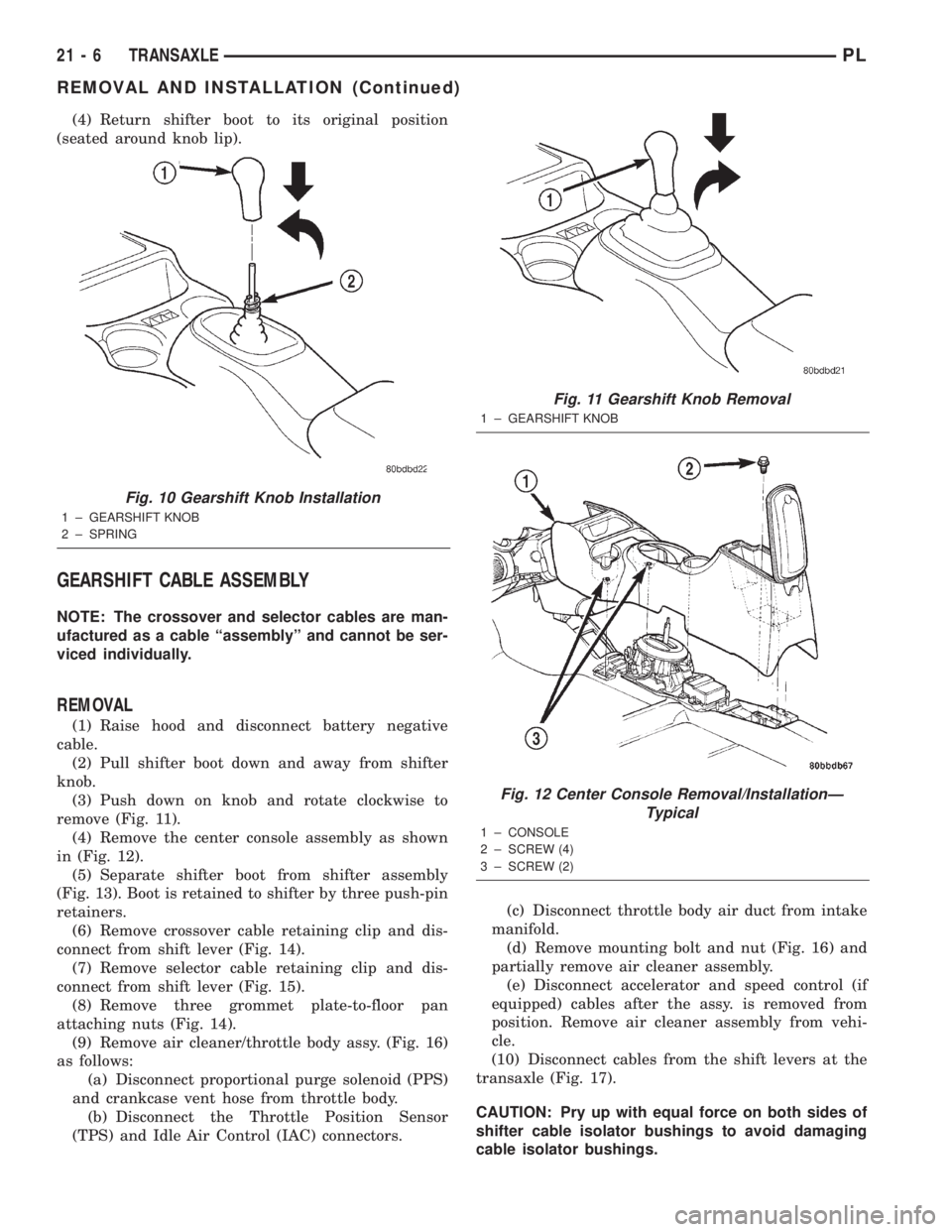
(4) Return shifter boot to its original position
(seated around knob lip).
GEARSHIFT CABLE ASSEMBLY
NOTE: The crossover and selector cables are man-
ufactured as a cable ªassemblyº and cannot be ser-
viced individually.
REMOVAL
(1) Raise hood and disconnect battery negative
cable.
(2) Pull shifter boot down and away from shifter
knob.
(3) Push down on knob and rotate clockwise to
remove (Fig. 11).
(4) Remove the center console assembly as shown
in (Fig. 12).
(5) Separate shifter boot from shifter assembly
(Fig. 13). Boot is retained to shifter by three push-pin
retainers.
(6) Remove crossover cable retaining clip and dis-
connect from shift lever (Fig. 14).
(7) Remove selector cable retaining clip and dis-
connect from shift lever (Fig. 15).
(8) Remove three grommet plate-to-floor pan
attaching nuts (Fig. 14).
(9) Remove air cleaner/throttle body assy. (Fig. 16)
as follows:
(a) Disconnect proportional purge solenoid (PPS)
and crankcase vent hose from throttle body.
(b) Disconnect the Throttle Position Sensor
(TPS) and Idle Air Control (IAC) connectors.(c) Disconnect throttle body air duct from intake
manifold.
(d) Remove mounting bolt and nut (Fig. 16) and
partially remove air cleaner assembly.
(e) Disconnect accelerator and speed control (if
equipped) cables after the assy. is removed from
position. Remove air cleaner assembly from vehi-
cle.
(10) Disconnect cables from the shift levers at the
transaxle (Fig. 17).
CAUTION: Pry up with equal force on both sides of
shifter cable isolator bushings to avoid damaging
cable isolator bushings.
Fig. 10 Gearshift Knob Installation
1 ± GEARSHIFT KNOB
2 ± SPRING
Fig. 11 Gearshift Knob Removal
1 ± GEARSHIFT KNOB
Fig. 12 Center Console Removal/InstallationÐ
Typical
1 ± CONSOLE
2 ± SCREW (4)
3 ± SCREW (2)
21 - 6 TRANSAXLEPL
REMOVAL AND INSTALLATION (Continued)
Page 922 of 1285
(a) Connect the accelerator and speed control (if
equipped) cables to the air cleaner/throttle body
assy.
(b) Install assy into position, making sure the
air cleaner locating slot is engaged to the battery
bracket tab, and tighten fasteners to 14 N´m (120
in. lbs.) torque.
(c) Verify throttle body duct is fully seated to
intake manifold and tighten clamp to 5 N´m (40 in.
lbs.) torque.(d) Connect the Throttle Position Sensor (TPS)
and Idle Air Control (IAC) connectors.
(e) Connect proportional purge solenoid (PPS)
and crankcase vent hose from throttle body.
(17) Connect battery negative cable.
GEARSHIFT MECHANISM REPLACEMENT
REMOVAL
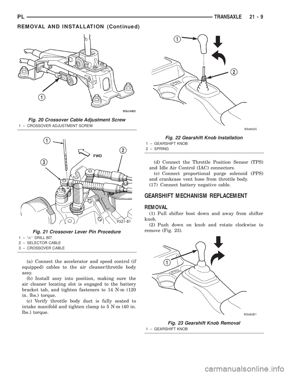
(1) Pull shifter boot down and away from shifter
knob.
(2) Push down on knob and rotate clockwise to
remove (Fig. 23).
Fig. 20 Crossover Cable Adjustment Screw
1 ± CROSSOVER ADJUSTMENT SCREW
Fig. 21 Crossover Lever Pin Procedure
1±1¤488DRILL BIT
2 ± SELECTOR CABLE
3 ± CROSSOVER CABLE
Fig. 22 Gearshift Knob Installation
1 ± GEARSHIFT KNOB
2 ± SPRING
Fig. 23 Gearshift Knob Removal
1 ± GEARSHIFT KNOB
PLTRANSAXLE 21 - 9
REMOVAL AND INSTALLATION (Continued)
Page 924 of 1285
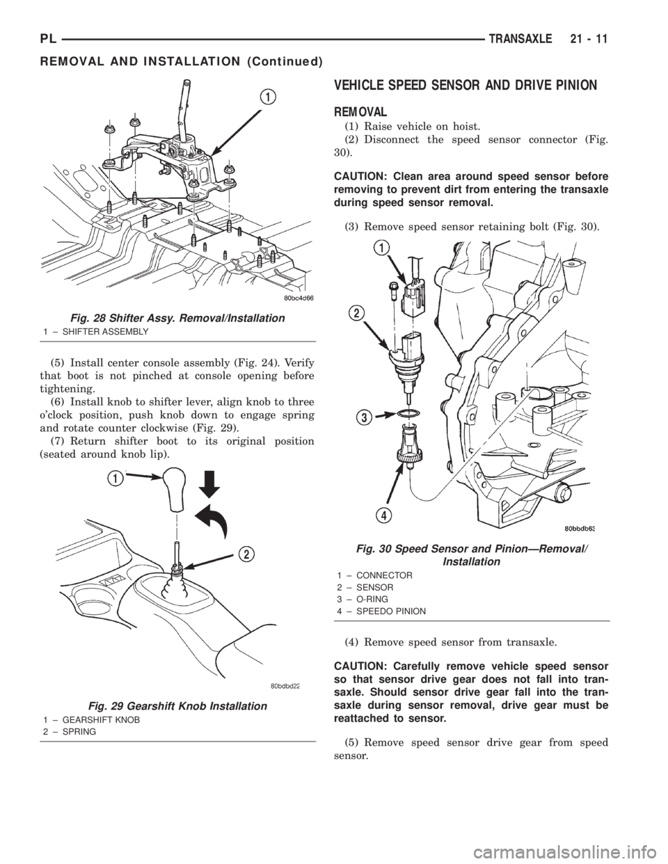
(5) Install center console assembly (Fig. 24). Verify
that boot is not pinched at console opening before
tightening.
(6) Install knob to shifter lever, align knob to three
o'clock position, push knob down to engage spring
and rotate counter clockwise (Fig. 29).
(7) Return shifter boot to its original position
(seated around knob lip).
VEHICLE SPEED SENSOR AND DRIVE PINION
REMOVAL
(1) Raise vehicle on hoist.
(2) Disconnect the speed sensor connector (Fig.
30).
CAUTION: Clean area around speed sensor before
removing to prevent dirt from entering the transaxle
during speed sensor removal.
(3) Remove speed sensor retaining bolt (Fig. 30).
(4) Remove speed sensor from transaxle.
CAUTION: Carefully remove vehicle speed sensor
so that sensor drive gear does not fall into tran-
saxle. Should sensor drive gear fall into the tran-
saxle during sensor removal, drive gear must be
reattached to sensor.
(5) Remove speed sensor drive gear from speed
sensor.
Fig. 28 Shifter Assy. Removal/Installation
1 ± SHIFTER ASSEMBLY
Fig. 29 Gearshift Knob Installation
1 ± GEARSHIFT KNOB
2 ± SPRING
Fig. 30 Speed Sensor and PinionÐRemoval/
Installation
1 ± CONNECTOR
2 ± SENSOR
3 ± O-RING
4 ± SPEEDO PINION
PLTRANSAXLE 21 - 11
REMOVAL AND INSTALLATION (Continued)
Page 925 of 1285
INSTALLATION
(1) Install pinion gear to speed sensor (Fig. 30).
(2) Using a NEW o-ring, install the speed sensor
to the transaxle (Fig. 30).
(3) Install the bolt and torque to 7 N´m (60 in.
lbs.).
(4) Connect speed sensor connector (Fig. 30).
(5) Lower vehicle and road test to verify proper
speedometer operation.
BACK-UP LAMP SWITCH
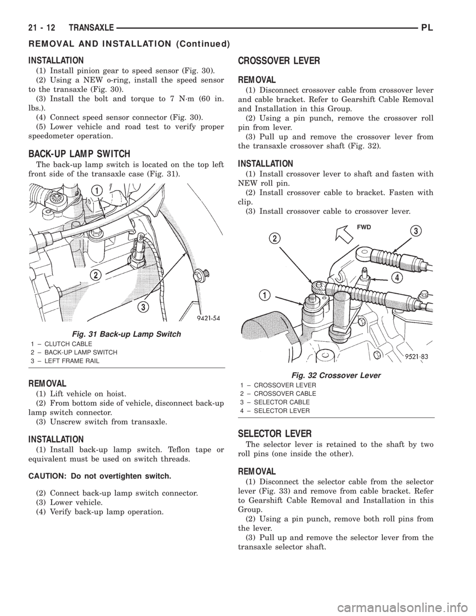
The back-up lamp switch is located on the top left
front side of the transaxle case (Fig. 31).
REMOVAL
(1) Lift vehicle on hoist.
(2) From bottom side of vehicle, disconnect back-up
lamp switch connector.
(3) Unscrew switch from transaxle.
INSTALLATION
(1) Install back-up lamp switch. Teflon tape or
equivalent must be used on switch threads.
CAUTION: Do not overtighten switch.
(2) Connect back-up lamp switch connector.
(3) Lower vehicle.
(4) Verify back-up lamp operation.
CROSSOVER LEVER
REMOVAL
(1) Disconnect crossover cable from crossover lever
and cable bracket. Refer to Gearshift Cable Removal
and Installation in this Group.
(2) Using a pin punch, remove the crossover roll
pin from lever.
(3) Pull up and remove the crossover lever from
the transaxle crossover shaft (Fig. 32).
INSTALLATION
(1) Install crossover lever to shaft and fasten with
NEW roll pin.
(2) Install crossover cable to bracket. Fasten with
clip.
(3) Install crossover cable to crossover lever.
SELECTOR LEVER
The selector lever is retained to the shaft by two
roll pins (one inside the other).
REMOVAL
(1) Disconnect the selector cable from the selector
lever (Fig. 33) and remove from cable bracket. Refer
to Gearshift Cable Removal and Installation in this
Group.
(2) Using a pin punch, remove both roll pins from
the lever.
(3) Pull up and remove the selector lever from the
transaxle selector shaft.
Fig. 31 Back-up Lamp Switch
1 ± CLUTCH CABLE
2 ± BACK-UP LAMP SWITCH
3 ± LEFT FRAME RAIL
Fig. 32 Crossover Lever
1 ± CROSSOVER LEVER
2 ± CROSSOVER CABLE
3 ± SELECTOR CABLE
4 ± SELECTOR LEVER
21 - 12 TRANSAXLEPL
REMOVAL AND INSTALLATION (Continued)
Page 927 of 1285
TRANSAXLE
REMOVAL
(1) Raise hood.
(2) Disconnect both battery cables, remove battery
hold down clamp and bolt, and remove battery.
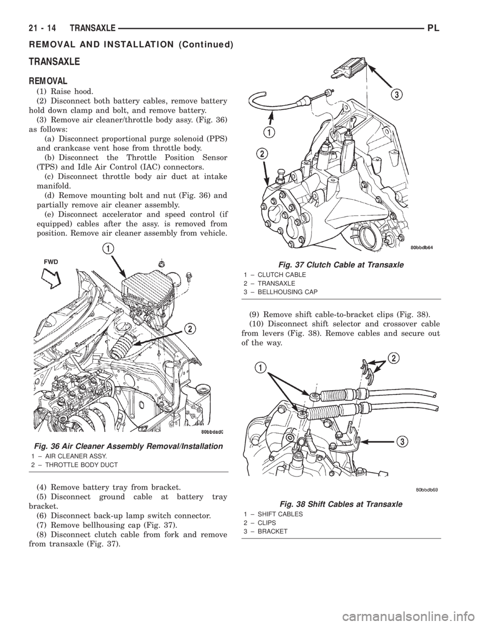
(3) Remove air cleaner/throttle body assy. (Fig. 36)
as follows:
(a) Disconnect proportional purge solenoid (PPS)
and crankcase vent hose from throttle body.
(b) Disconnect the Throttle Position Sensor
(TPS) and Idle Air Control (IAC) connectors.
(c) Disconnect throttle body air duct at intake
manifold.
(d) Remove mounting bolt and nut (Fig. 36) and
partially remove air cleaner assembly.
(e)
Disconnect accelerator and speed control (if
equipped) cables after the assy. is removed from
position. Remove air cleaner assembly from vehicle.
(4) Remove battery tray from bracket.
(5) Disconnect ground cable at battery tray
bracket.
(6) Disconnect back-up lamp switch connector.
(7) Remove bellhousing cap (Fig. 37).
(8) Disconnect clutch cable from fork and remove
from transaxle (Fig. 37).(9) Remove shift cable-to-bracket clips (Fig. 38).
(10) Disconnect shift selector and crossover cable
from levers (Fig. 38). Remove cables and secure out
of the way.
Fig. 36 Air Cleaner Assembly Removal/Installation
1 ± AIR CLEANER ASSY.
2 ± THROTTLE BODY DUCT
Fig. 37 Clutch Cable at Transaxle
1 ± CLUTCH CABLE
2 ± TRANSAXLE
3 ± BELLHOUSING CAP
Fig. 38 Shift Cables at Transaxle
1 ± SHIFT CABLES
2 ± CLIPS
3 ± BRACKET
21 - 14 TRANSAXLEPL
REMOVAL AND INSTALLATION (Continued)