2000 DODGE NEON sensor
[x] Cancel search: sensorPage 988 of 1285
INSTALLATION
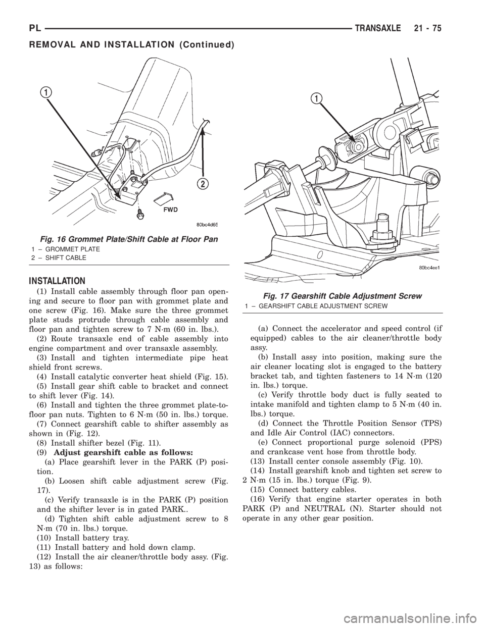
(1) Install cable assembly through floor pan open-
ing and secure to floor pan with grommet plate and
one screw (Fig. 16). Make sure the three grommet
plate studs protrude through cable assembly and
floor pan and tighten screw to 7 N´m (60 in. lbs.).
(2) Route transaxle end of cable assembly into
engine compartment and over transaxle assembly.
(3) Install and tighten intermediate pipe heat
shield front screws.
(4) Install catalytic converter heat shield (Fig. 15).
(5) Install gear shift cable to bracket and connect
to shift lever (Fig. 14).
(6) Install and tighten the three grommet plate-to-
floor pan nuts. Tighten to 6 N´m (50 in. lbs.) torque.
(7) Connect gearshift cable to shifter assembly as
shown in (Fig. 12).
(8) Install shifter bezel (Fig. 11).
(9)Adjust gearshift cable as follows:
(a) Place gearshift lever in the PARK (P) posi-
tion.
(b) Loosen shift cable adjustment screw (Fig.
17).
(c) Verify transaxle is in the PARK (P) position
and the shifter lever is in gated PARK..
(d) Tighten shift cable adjustment screw to 8
N´m (70 in. lbs.) torque.
(10) Install battery tray.
(11) Install battery and hold down clamp.
(12) Install the air cleaner/throttle body assy. (Fig.
13) as follows:(a) Connect the accelerator and speed control (if
equipped) cables to the air cleaner/throttle body
assy.
(b) Install assy into position, making sure the
air cleaner locating slot is engaged to the battery
bracket tab, and tighten fasteners to 14 N´m (120
in. lbs.) torque.
(c) Verify throttle body duct is fully seated to
intake manifold and tighten clamp to 5 N´m (40 in.
lbs.) torque.
(d) Connect the Throttle Position Sensor (TPS)
and Idle Air Control (IAC) connectors.
(e) Connect proportional purge solenoid (PPS)
and crankcase vent hose from throttle body.
(13) Install center console assembly (Fig. 10).
(14) Install gearshift knob and tighten set screw to
2 N´m (15 in. lbs.) torque (Fig. 9).
(15) Connect battery cables.
(16) Verify that engine starter operates in both
PARK (P) and NEUTRAL (N). Starter should not
operate in any other gear position.
Fig. 16 Grommet Plate/Shift Cable at Floor Pan
1 ± GROMMET PLATE
2 ± SHIFT CABLE
Fig. 17 Gearshift Cable Adjustment Screw
1 ± GEARSHIFT CABLE ADJUSTMENT SCREW
PLTRANSAXLE 21 - 75
REMOVAL AND INSTALLATION (Continued)
Page 990 of 1285
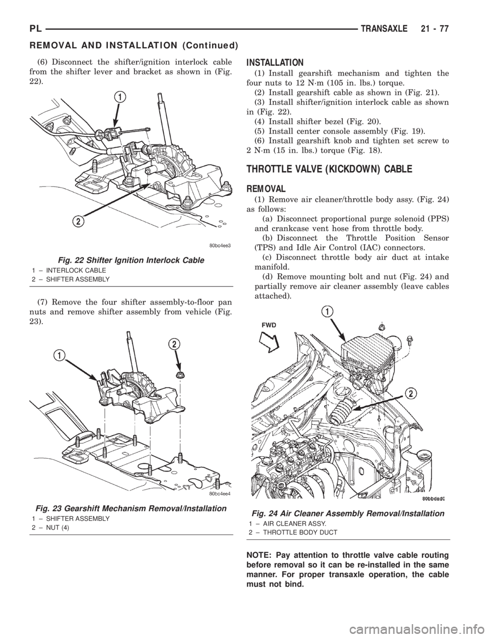
(6) Disconnect the shifter/ignition interlock cable
from the shifter lever and bracket as shown in (Fig.
22).
(7) Remove the four shifter assembly-to-floor pan
nuts and remove shifter assembly from vehicle (Fig.
23).INSTALLATION
(1) Install gearshift mechanism and tighten the
four nuts to 12 N´m (105 in. lbs.) torque.
(2) Install gearshift cable as shown in (Fig. 21).
(3) Install shifter/ignition interlock cable as shown
in (Fig. 22).
(4) Install shifter bezel (Fig. 20).
(5) Install center console assembly (Fig. 19).
(6) Install gearshift knob and tighten set screw to
2 N´m (15 in. lbs.) torque (Fig. 18).
THROTTLE VALVE (KICKDOWN) CABLE
REMOVAL
(1) Remove air cleaner/throttle body assy. (Fig. 24)
as follows:
(a) Disconnect proportional purge solenoid (PPS)
and crankcase vent hose from throttle body.
(b) Disconnect the Throttle Position Sensor
(TPS) and Idle Air Control (IAC) connectors.
(c) Disconnect throttle body air duct at intake
manifold.
(d) Remove mounting bolt and nut (Fig. 24) and
partially remove air cleaner assembly (leave cables
attached).
NOTE: Pay attention to throttle valve cable routing
before removal so it can be re-installed in the same
manner. For proper transaxle operation, the cable
must not bind.
Fig. 22 Shifter Ignition Interlock Cable
1 ± INTERLOCK CABLE
2 ± SHIFTER ASSEMBLY
Fig. 23 Gearshift Mechanism Removal/Installation
1 ± SHIFTER ASSEMBLY
2 ± NUT (4)Fig. 24 Air Cleaner Assembly Removal/Installation
1 ± AIR CLEANER ASSY.
2 ± THROTTLE BODY DUCT
PLTRANSAXLE 21 - 77
REMOVAL AND INSTALLATION (Continued)
Page 991 of 1285
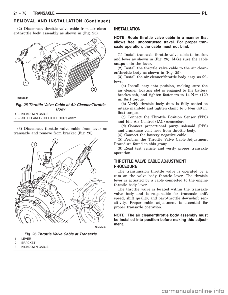
(2) Disconnect throttle valve cable from air clean-
er/throttle body assembly as shown in (Fig. 25).
(3) Disconnect throttle valve cable from lever on
transaxle and remove from bracket (Fig. 26).INSTALLATION
NOTE: Route throttle valve cable in a manner that
allows free, unobstructed travel. For proper tran-
saxle operation, the cable must not bind.
(1) Install transaxle throttle valve cable to bracket
and lever as shown in (Fig. 26). Make sure the cable
snapsonto the lever.
(2) Install the throttle valve cable to the air clean-
er/throttle body as shown in (Fig. 25).
(3) Install the air cleaner/throttle body assy. as fol-
lows:
(a) Install assy into position, making sure the
air cleaner locating slot is engaged to the battery
bracket tab, and tighten fasteners to 14 N´m (120
in. lbs.) torque.
(b) Verify throttle body duct is fully seated to
intake manifold and tighten clamp to 5 N´m (40 in.
lbs.) torque.
(c) Connect the Throttle Position Sensor (TPS)
and Idle Air Control (IAC) connectors.
(d) Connect proportional purge solenoid (PPS)
and crankcase vent hose from throttle body.
(4) Connect the battery negative cable.
(5) Perform the Throttle Valve Cable Adjustment
Procedure found in this group.
(6) Road test vehicle and verify proper transaxle
operation.
THROTTLE VALVE CABLE ADJUSTMENT
PROCEDURE
The transmission throttle valve is operated by a
cam on the valve body throttle lever. The throttle
lever is actuated by a cable connected to the engine
throttle body lever.
The throttle valve is located within the transaxle
valve body and is responsible for transaxle shift
speed, shift quality, and part-throttle downshift sen-
sitivity. Proper cable adjustment is essential for
proper transaxle operation.
NOTE: The air cleaner/throttle body assembly must
be installed into position before making this adjust-
ment.
Fig. 25 Throttle Valve Cable at Air Cleaner/Throttle
Body
1 ± KICKDOWN CABLE
2 ± AIR CLEANER/THROTTLE BODY ASSY.
Fig. 26 Throttle Valve Cable at Transaxle
1 ± LEVER
2 ± BRACKET
3 ± KICKDOWN CABLE
21 - 78 TRANSAXLEPL
REMOVAL AND INSTALLATION (Continued)
Page 996 of 1285
(3) Install steering column upper and lower
shrouds (Fig. 40).
(4) Install steering column lower cover (Fig. 39).
VEHICLE SPEED SENSOR PINION GEAR
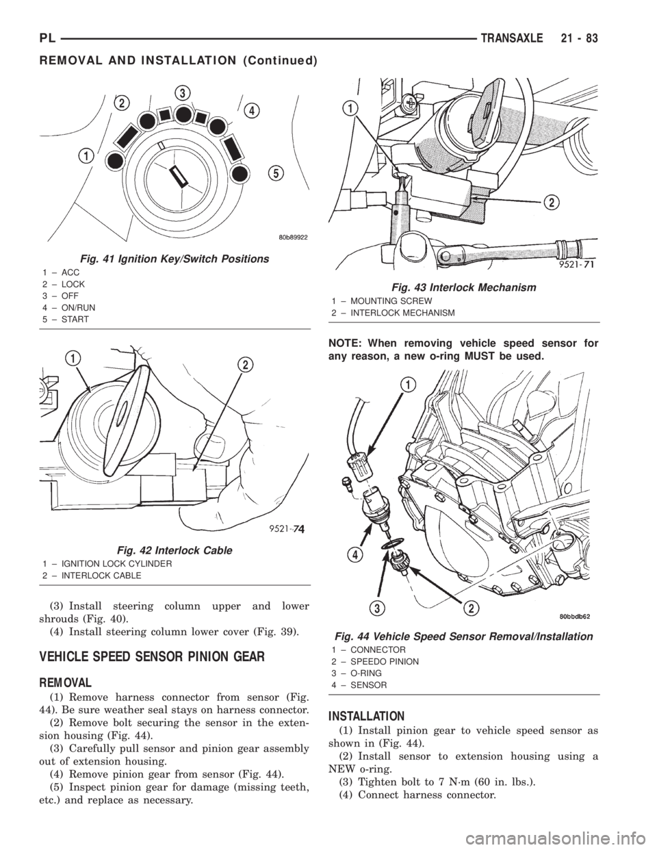
REMOVAL
(1) Remove harness connector from sensor (Fig.
44). Be sure weather seal stays on harness connector.
(2) Remove bolt securing the sensor in the exten-
sion housing (Fig. 44).
(3) Carefully pull sensor and pinion gear assembly
out of extension housing.
(4) Remove pinion gear from sensor (Fig. 44).
(5) Inspect pinion gear for damage (missing teeth,
etc.) and replace as necessary.NOTE: When removing vehicle speed sensor for
any reason, a new o-ring MUST be used.
INSTALLATION
(1) Install pinion gear to vehicle speed sensor as
shown in (Fig. 44).
(2) Install sensor to extension housing using a
NEW o-ring.
(3) Tighten bolt to 7 N´m (60 in. lbs.).
(4) Connect harness connector.
Fig. 41 Ignition Key/Switch Positions
1 ± ACC
2 ± LOCK
3 ± OFF
4 ± ON/RUN
5±START
Fig. 42 Interlock Cable
1 ± IGNITION LOCK CYLINDER
2 ± INTERLOCK CABLE
Fig. 43 Interlock Mechanism
1 ± MOUNTING SCREW
2 ± INTERLOCK MECHANISM
Fig. 44 Vehicle Speed Sensor Removal/Installation
1 ± CONNECTOR
2 ± SPEEDO PINION
3 ± O-RING
4 ± SENSOR
PLTRANSAXLE 21 - 83
REMOVAL AND INSTALLATION (Continued)
Page 997 of 1285
PARK/NEUTRAL STARTING AND BACK-UP
LAMP SWITCH
TEST
The park/neutral starting switch is the center ter-
minal of the three terminal switch. It provides
ground for the starter solenoid circuit through the
selector lever in PARK and NEUTRAL positions only.
(1) To test switch, remove wiring connector from
switch and test for continuity between center pin of
switch and transaxle case. Continuity should exist
only when transaxle is in PARK or NEUTRAL.
(2) Check gearshift cable adjustment before replac-
ing a switch that tests bad.
REMOVAL
(1) Unscrew switch from transaxle case allowing
fluid to drain into a container. Move selector lever to
PARK, then to NEUTRAL position, and inspect to see
the switch operating lever fingers are centered in
switch opening.
INSTALLATION
(1) Screw the switch with a new seal into tran-
saxle case and tighten to 33 N´m (24 ft. lbs.). Retest
switch with the test lamp.
(2) Add fluid to transaxle to bring up to proper
level.
(3) The back-up lamp switch circuit is through the
two outside terminals of the three terminal switch.
(4) To test switch, remove wiring connector from
switch and test for continuity between the two out-
side pins.
(5) Continuity should exist only with transaxle in
REVERSE position.
(6) No continuity should exist from either pin to
the case.
TRANSAXLE AND TORQUE CONVERTER
REMOVAL
(1) Raise hood.
(2) Disconnect both battery cables, remove battery
hold down clamp and bolt, and remove battery.
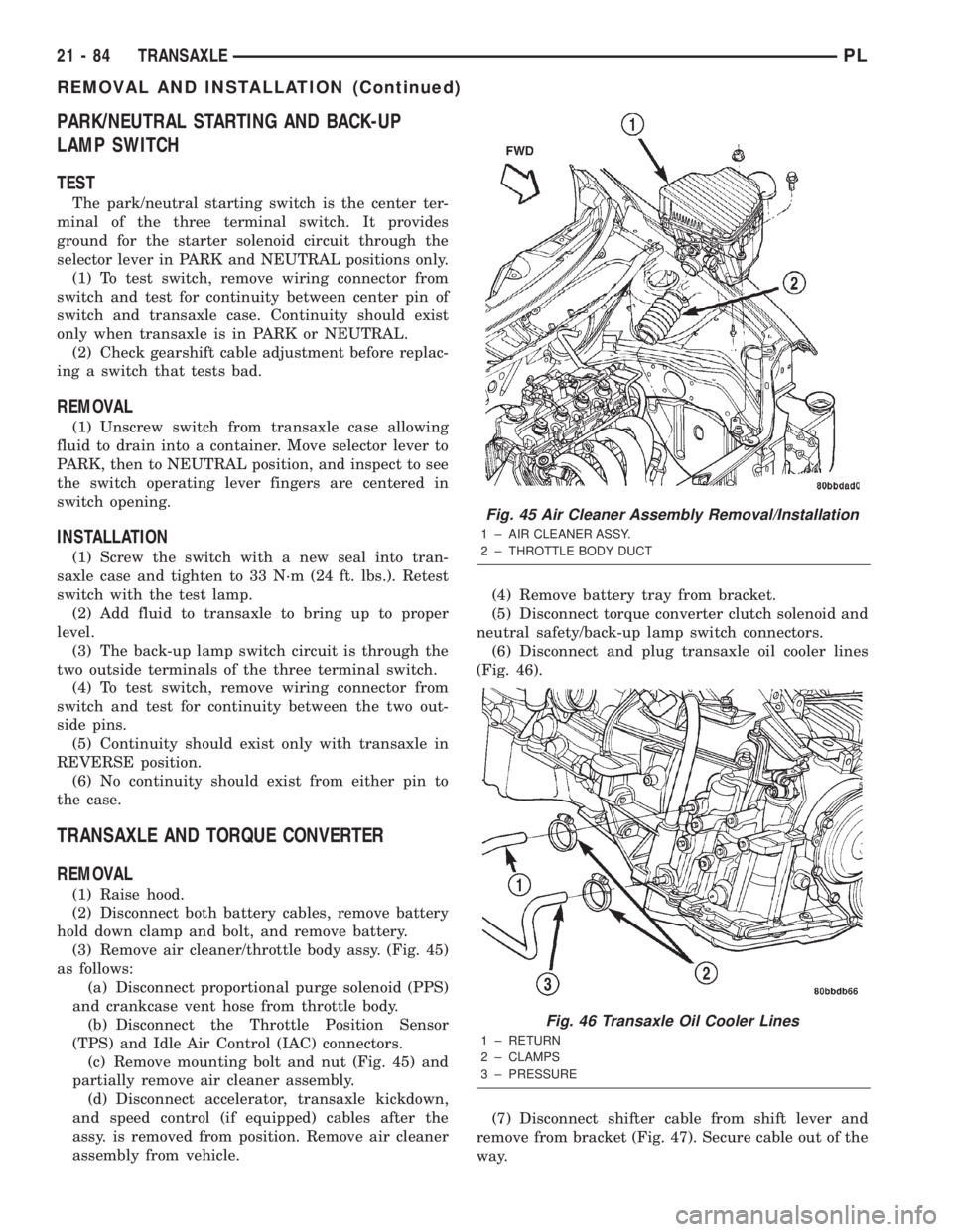
(3) Remove air cleaner/throttle body assy. (Fig. 45)
as follows:
(a) Disconnect proportional purge solenoid (PPS)
and crankcase vent hose from throttle body.
(b) Disconnect the Throttle Position Sensor
(TPS) and Idle Air Control (IAC) connectors.
(c) Remove mounting bolt and nut (Fig. 45) and
partially remove air cleaner assembly.
(d) Disconnect accelerator, transaxle kickdown,
and speed control (if equipped) cables after the
assy. is removed from position. Remove air cleaner
assembly from vehicle.(4) Remove battery tray from bracket.
(5) Disconnect torque converter clutch solenoid and
neutral safety/back-up lamp switch connectors.
(6) Disconnect and plug transaxle oil cooler lines
(Fig. 46).
(7) Disconnect shifter cable from shift lever and
remove from bracket (Fig. 47). Secure cable out of the
way.
Fig. 45 Air Cleaner Assembly Removal/Installation
1 ± AIR CLEANER ASSY.
2 ± THROTTLE BODY DUCT
Fig. 46 Transaxle Oil Cooler Lines
1 ± RETURN
2 ± CLAMPS
3 ± PRESSURE
21 - 84 TRANSAXLEPL
REMOVAL AND INSTALLATION (Continued)
Page 998 of 1285
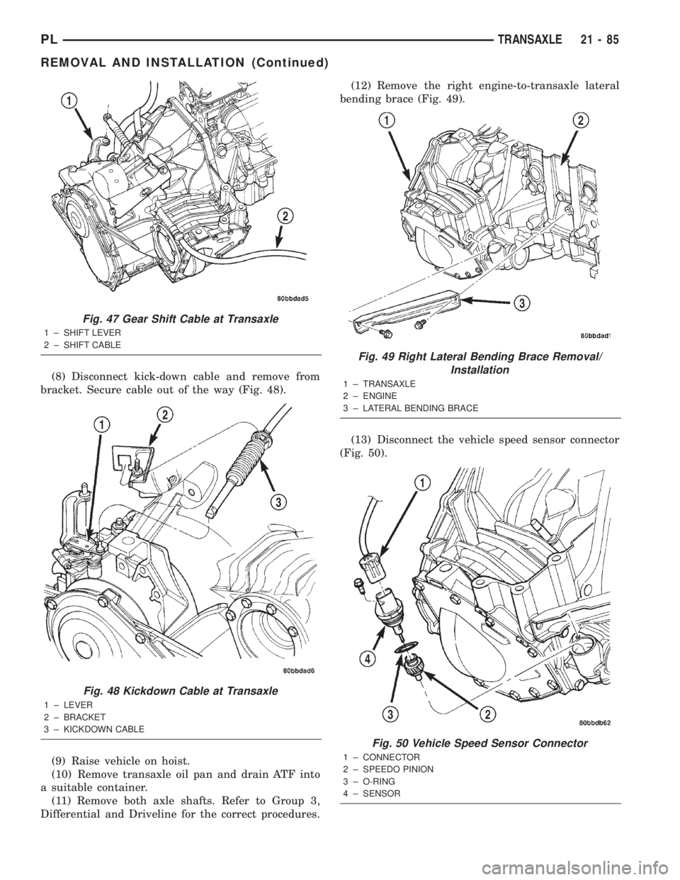
(8) Disconnect kick-down cable and remove from
bracket. Secure cable out of the way (Fig. 48).
(9) Raise vehicle on hoist.
(10) Remove transaxle oil pan and drain ATF into
a suitable container.
(11) Remove both axle shafts. Refer to Group 3,
Differential and Driveline for the correct procedures.(12) Remove the right engine-to-transaxle lateral
bending brace (Fig. 49).
(13) Disconnect the vehicle speed sensor connector
(Fig. 50).
Fig. 47 Gear Shift Cable at Transaxle
1 ± SHIFT LEVER
2 ± SHIFT CABLE
Fig. 48 Kickdown Cable at Transaxle
1 ± LEVER
2 ± BRACKET
3 ± KICKDOWN CABLE
Fig. 49 Right Lateral Bending Brace Removal/
Installation
1 ± TRANSAXLE
2 ± ENGINE
3 ± LATERAL BENDING BRACE
Fig. 50 Vehicle Speed Sensor Connector
1 ± CONNECTOR
2 ± SPEEDO PINION
3 ± O-RING
4 ± SENSOR
PLTRANSAXLE 21 - 85
REMOVAL AND INSTALLATION (Continued)
Page 1001 of 1285
(c) Tighten the collar-to-transaxle bolts to 108
N´m (80 ft. lbs.) torque.
(d) Final torque the collar-to-oil pan bolts to 54
N´m (40 ft. lbs.) torque.
(11) Install both front axle driveshafts. Refer to
Group 3, Differential and Driveline for the correct
procedures.
(12) Connect vehicle speed sensor connector (Fig.
50).
(13) Install right lateral bending brace and tighten
bolts to 81 N´m (60 ft. lbs.) torque.
(14) Lower vehicle.
(15) Connect transaxle cooler lines and tighten
clamps (Fig. 46).
(16) Connect torque converter clutch solenoid and
neutral safety/back-up lamp switch connectors.
(17) Install transaxle dipstick tube.
(18) Install gear shift cable to bracket and connect
to shift lever (Fig. 47).
(19) Install transaxle kickdown cable to bracket
and lever as shown in (Fig. 48).
(20) Install battery lower tray and battery, and
tighten battery hold down clamp to secure battery.
(21) Install the air cleaner/throttle body assy. as
follows:
(a) Connect the accelerator, transaxle kickdown,
and speed control (if equipped) cables to the air
cleaner/throttle body assy.
(b) Install assy into position and tighten fasten-
ers to 14 N´m (120 in. lbs.) torque.
(c) Connect the Throttle Position Sensor (TPS)
and Idle Air Control (IAC) connectors.
(d) Connect proportional purge solenoid (PPS)
and crankcase vent hose from throttle body.
(22) Fill transaxle with a suitable amount of
ATF+4.
(23) Road test vehicle.
(24) Check for leaks, inspect fluid level, and adjust
as necessary.
PUMP OIL SEAL
The pump oil seal can be replaced without remov-
ing the pump and reaction shaft support assembly
from the transaxle case.
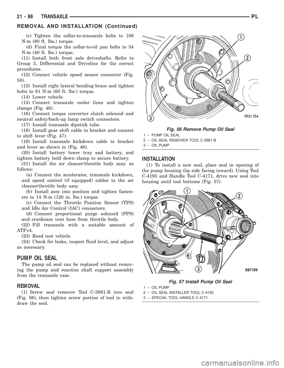
REMOVAL
(1) Screw seal remover Tool C-3981-B into seal
(Fig. 56), then tighten screw portion of tool to with-
draw the seal.
INSTALLATION
(1) To install a new seal, place seal in opening of
the pump housing (lip side facing inward). Using Tool
C-4193 and Handle Tool C-4171, drive new seal into
housing until tool bottoms (Fig. 57).
Fig. 56 Remove Pump Oil Seal
1 ± PUMP OIL SEAL
2 ± OIL SEAL REMOVER TOOL C-3981-B
3 ± OIL PUMP
Fig. 57 Install Pump Oil Seal
1 ± OIL PUMP
2 ± OIL SEAL INSTALLER TOOL C-4193
3 ± SPECIAL TOOL HANDLE C-4171
21 - 88 TRANSAXLEPL
REMOVAL AND INSTALLATION (Continued)
Page 1088 of 1285
EMISSION CONTROL SYSTEMS
TABLE OF CONTENTS
page page
ON-BOARD DIAGNOSTICS................... 1 EVAPORATIVE EMISSION CONTROLS......... 25
ON-BOARD DIAGNOSTICS
TABLE OF CONTENTS
page page
DESCRIPTION AND OPERATION
SYSTEM DESCRIPTION....................1
TASK MANAGER..........................2
MALFUNCTION INDICATOR LAMP (MIL)........5
DRB III STATE DISPLAY TEST MODE..........5
DRB III CIRCUIT ACTUATION TEST MODE......5
DIAGNOSTIC TROUBLE CODES..............5
DIAGNOSTIC TROUBLE CODE
DESCRIPTIONS.........................6MONITORED SYSTEMS....................15
TRIP DEFINITION........................19
MONITORED COMPONENT.................19
NON-MONITORED CIRCUITS...............23
HIGH AND LOW LIMITS....................24
LOAD VALUE............................24
DESCRIPTION AND OPERATION
SYSTEM DESCRIPTION
DESCRIPTION
OBD II requires that vehicles falling under OBD II
guidelines utilize the following system monitors:
²Comprehensive Component Monitor (inputs/out-
puts for powertrain management that affect emis-
sions, but do not have a specific major monitor)
²Fuel Control Monitor (fuel compensation
required to maintain stoichiometric ratio rich/lean)
²Misfire Monitor (change in crankshaft speed)
²Oxygen Sensor Heater Monitor (response and
performance of oxygen sensors)
²Catalyst Monitor (Performance and efficiency of
catalyst)
²Evaporative Emissions Monitor (performance of
and leaks from EVAP system)
²Exhaust Gas Recirculation Monitor (flow perfor-
mance of EGR system)
The software was rewritten to enable the PCM to
carry out the responsibilities to meet these required
guidelines. The PCM now contains a Task Manager.
OPERATION
The Powertrain Control Module (PCM) monitors
many different circuits in the fuel injection, ignition,
emission and engine systems. If the PCM senses a
problem with a monitored circuit often enough to
indicate an actual problem, it stores a Diagnostic
Trouble Code (DTC) in the PCM's memory. If the
code applies to a non-emissions related component or
system, and the problem is repaired or ceases to
exist, the PCM cancels the code after 40 warmup
cycles. Diagnostic trouble codes that affect vehicle
emissions illuminate the Malfunction Indicator Lamp
(MIL). Refer to Malfunction Indicator Lamp in this
section.
Certain criteria must be met before the PCM
stores a DTC in memory. The criteria may be a spe-
cific range of engine RPM, engine temperature,
and/or input voltage to the PCM.
The PCM might not store a DTC for a monitored
circuit even though a malfunction has occurred. This
may happen because one of the DTC criteria for the
circuit has not been met.For example, assume the
diagnostic trouble code criteria requires the PCM to
monitor the circuit only when the engine operates
between 750 and 2000 RPM. Suppose the sensor's
output circuit shorts to ground when engine operates
above 2400 RPM (resulting in 0 volt input to the
PLEMISSION CONTROL SYSTEMS 25 - 1