2000 DODGE NEON sensor
[x] Cancel search: sensorPage 861 of 1285
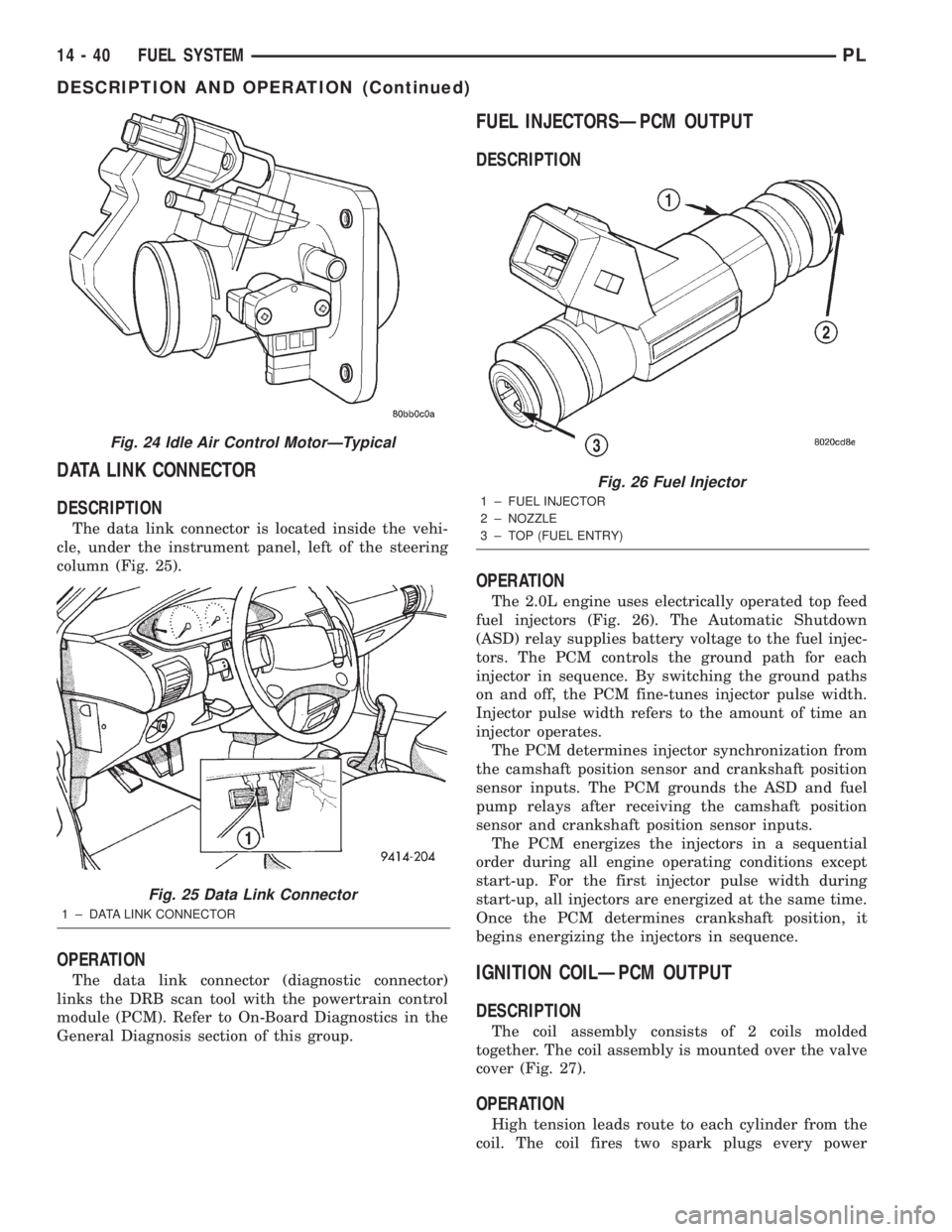
DATA LINK CONNECTOR
DESCRIPTION
The data link connector is located inside the vehi-
cle, under the instrument panel, left of the steering
column (Fig. 25).
OPERATION
The data link connector (diagnostic connector)
links the DRB scan tool with the powertrain control
module (PCM). Refer to On-Board Diagnostics in the
General Diagnosis section of this group.
FUEL INJECTORSÐPCM OUTPUT
DESCRIPTION
OPERATION
The 2.0L engine uses electrically operated top feed
fuel injectors (Fig. 26). The Automatic Shutdown
(ASD) relay supplies battery voltage to the fuel injec-
tors. The PCM controls the ground path for each
injector in sequence. By switching the ground paths
on and off, the PCM fine-tunes injector pulse width.
Injector pulse width refers to the amount of time an
injector operates.
The PCM determines injector synchronization from
the camshaft position sensor and crankshaft position
sensor inputs. The PCM grounds the ASD and fuel
pump relays after receiving the camshaft position
sensor and crankshaft position sensor inputs.
The PCM energizes the injectors in a sequential
order during all engine operating conditions except
start-up. For the first injector pulse width during
start-up, all injectors are energized at the same time.
Once the PCM determines crankshaft position, it
begins energizing the injectors in sequence.
IGNITION COILÐPCM OUTPUT
DESCRIPTION
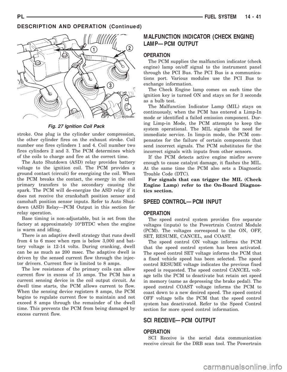
The coil assembly consists of 2 coils molded
together. The coil assembly is mounted over the valve
cover (Fig. 27).
OPERATION
High tension leads route to each cylinder from the
coil. The coil fires two spark plugs every power
Fig. 24 Idle Air Control MotorÐTypical
Fig. 25 Data Link Connector
1 ± DATA LINK CONNECTOR
Fig. 26 Fuel Injector
1 ± FUEL INJECTOR
2 ± NOZZLE
3 ± TOP (FUEL ENTRY)
14 - 40 FUEL SYSTEMPL
DESCRIPTION AND OPERATION (Continued)
Page 862 of 1285
stroke. One plug is the cylinder under compression,
the other cylinder fires on the exhaust stroke. Coil
number one fires cylinders 1 and 4. Coil number two
fires cylinders 2 and 3. The PCM determines which
of the coils to charge and fire at the correct time.
The Auto Shutdown (ASD) relay provides battery
voltage to the ignition coil. The PCM provides a
ground contact (circuit) for energizing the coil. When
the PCM breaks the contact, the energy in the coil
primary transfers to the secondary causing the
spark. The PCM will de-energize the ASD relay if it
does not receive the crankshaft position sensor and
camshaft position sensor inputs. Refer to Auto Shut-
down (ASD) RelayÐPCM Output in this section for
relay operation.
Base timing is non-adjustable, but is set from the
factory at approximately 10ÉBTDC when the engine
is warm and idling.
There is an adaptive dwell strategy that runs dwell
from 4 to 6 msec when rpm is below 3,000 and bat-
tery voltage is 12-14 volts. During cranking, dwell
can be as much as 200 msec. The adaptive dwell is
driven by the sensed current flow through the injec-
tor drivers. Current flow is limited to 8 amps.
The low resistance of the primary coils can allow
current flow in excess of 15 amps. The PCM has a
current sensing device in the coil output circuit. As
dwell time starts, the PCM allows current to flow.
When the sensing device registers 8 amps, the PCM
begins to regulate current flow to maintain and not
exceed 8 amps through the remainder of the dwell
time. This prevents the PCM from being damaged by
excess current flow.
MALFUNCTION INDICATOR (CHECK ENGINE)
LAMPÐPCM OUTPUT
OPERATION
The PCM supplies the malfunction indicator (check
engine) lamp on/off signal to the instrument panel
through the PCI Bus. The PCI Bus is a communica-
tions port. Various modules use the PCI Bus to
exchange information.
The Check Engine lamp comes on each time the
ignition key is turned ON and stays on for 3 seconds
as a bulb test.
The Malfunction Indicator Lamp (MIL) stays on
continuously, when the PCM has entered a Limp-In
mode or identified a failed emission component. Dur-
ing Limp-in Mode, the PCM attempts to keep the
system operational. The MIL signals the need for
immediate service. In limp-in mode, the PCM com-
pensates for the failure of certain components that
send incorrect signals. The PCM substitutes for the
incorrect signals with inputs from other sensors.
If the PCM detects active engine misfire severe
enough to cause catalyst damage, it flashes the MIL.
At the same time the PCM also sets a Diagnostic
Trouble Code (DTC).
For signals that can trigger the MIL (Check
Engine Lamp) refer to the On-Board Diagnos-
tics section.
SPEED CONTROLÐPCM INPUT
OPERATION
The speed control system provides five separate
voltages (inputs) to the Powertrain Control Module
(PCM). The voltages correspond to the ON, OFF,
SET, RESUME, CANCEL, and COAST.
The speed control ON voltage informs the PCM
that the speed control system has been activated.
The speed control SET voltage informs the PCM that
a fixed vehicle speed has been selected. The speed
control RESUME voltage indicates the previous fixed
speed is requested. The speed control CANCEL volt-
age tells the PCM to deactivate but retain set speed
in memory (same as depressing the brake pedal). The
speed control COAST voltage informs the PCM to
coast down to a new desired speed. The speed control
OFF voltage tells the PCM that the speed control
system has deactivated. Refer to the Speed Control
section for more speed control information.
SCI RECEIVEÐPCM OUTPUT
OPERATION
SCI Receive is the serial data communication
receive circuit for the DRB scan tool. The Powertrain
Fig. 27 Ignition Coil Pack
PLFUEL SYSTEM 14 - 41
DESCRIPTION AND OPERATION (Continued)
Page 863 of 1285
Control Module (PCM) receives data from the DRB
through the SCI Receive circuit.
TACHOMETERÐPCM OUTPUT
OPERATION
The PCM operates the tachometer on the instru-
ment panel. The PCM calculates engine RPM from
the crankshaft position sensor input. Sends the infor-
mation to the cluster across the bus.
TORQUE CONVERTOR CLUTCH SOLENOIDÐ
PCM OUTPUT
OPERATION
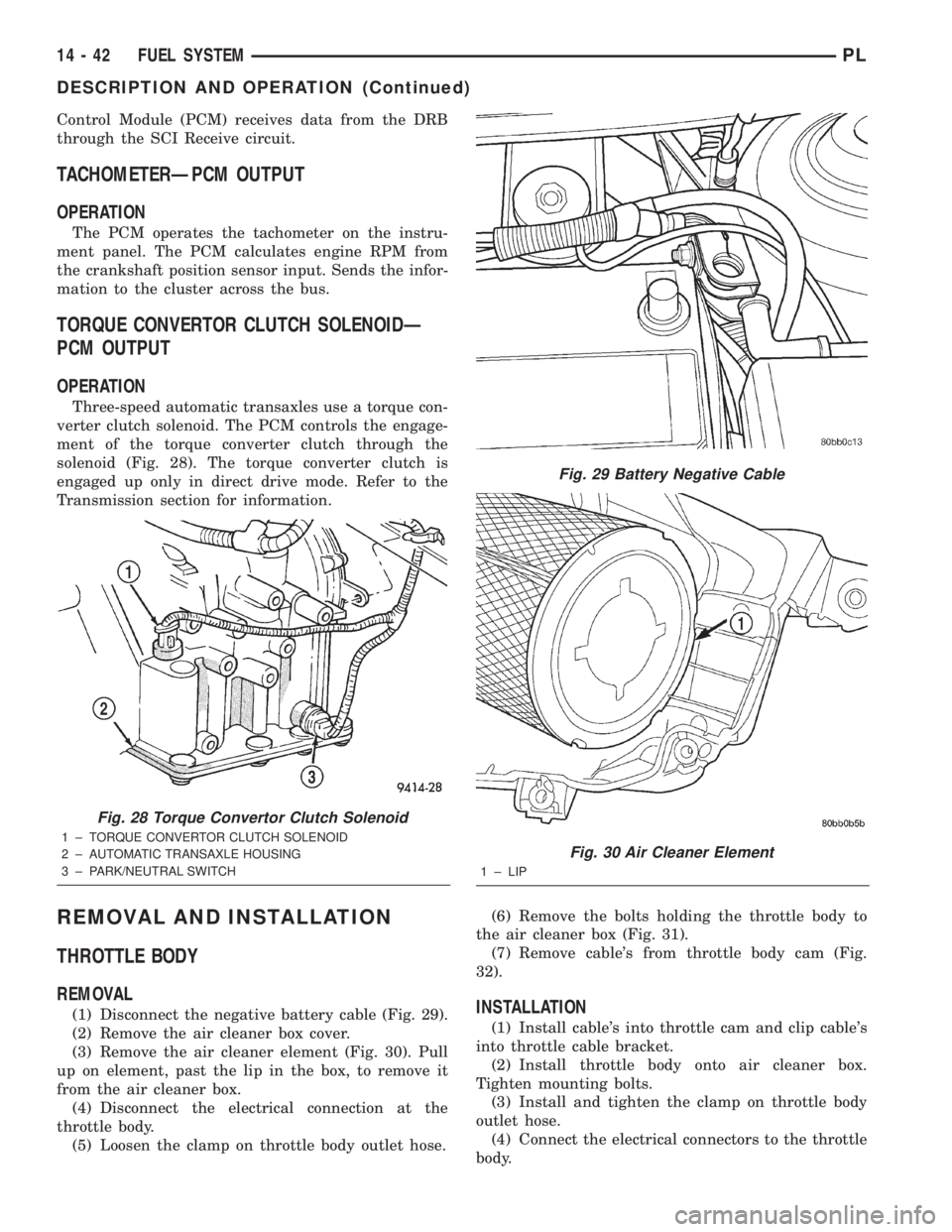
Three-speed automatic transaxles use a torque con-
verter clutch solenoid. The PCM controls the engage-
ment of the torque converter clutch through the
solenoid (Fig. 28). The torque converter clutch is
engaged up only in direct drive mode. Refer to the
Transmission section for information.
REMOVAL AND INSTALLATION
THROTTLE BODY
REMOVAL
(1) Disconnect the negative battery cable (Fig. 29).
(2) Remove the air cleaner box cover.
(3) Remove the air cleaner element (Fig. 30). Pull
up on element, past the lip in the box, to remove it
from the air cleaner box.
(4) Disconnect the electrical connection at the
throttle body.
(5) Loosen the clamp on throttle body outlet hose.(6) Remove the bolts holding the throttle body to
the air cleaner box (Fig. 31).
(7) Remove cable's from throttle body cam (Fig.
32).INSTALLATION
(1) Install cable's into throttle cam and clip cable's
into throttle cable bracket.
(2) Install throttle body onto air cleaner box.
Tighten mounting bolts.
(3) Install and tighten the clamp on throttle body
outlet hose.
(4) Connect the electrical connectors to the throttle
body.
Fig. 28 Torque Convertor Clutch Solenoid
1 ± TORQUE CONVERTOR CLUTCH SOLENOID
2 ± AUTOMATIC TRANSAXLE HOUSING
3 ± PARK/NEUTRAL SWITCH
Fig. 29 Battery Negative Cable
Fig. 30 Air Cleaner Element
1 ± LIP
14 - 42 FUEL SYSTEMPL
DESCRIPTION AND OPERATION (Continued)
Page 864 of 1285
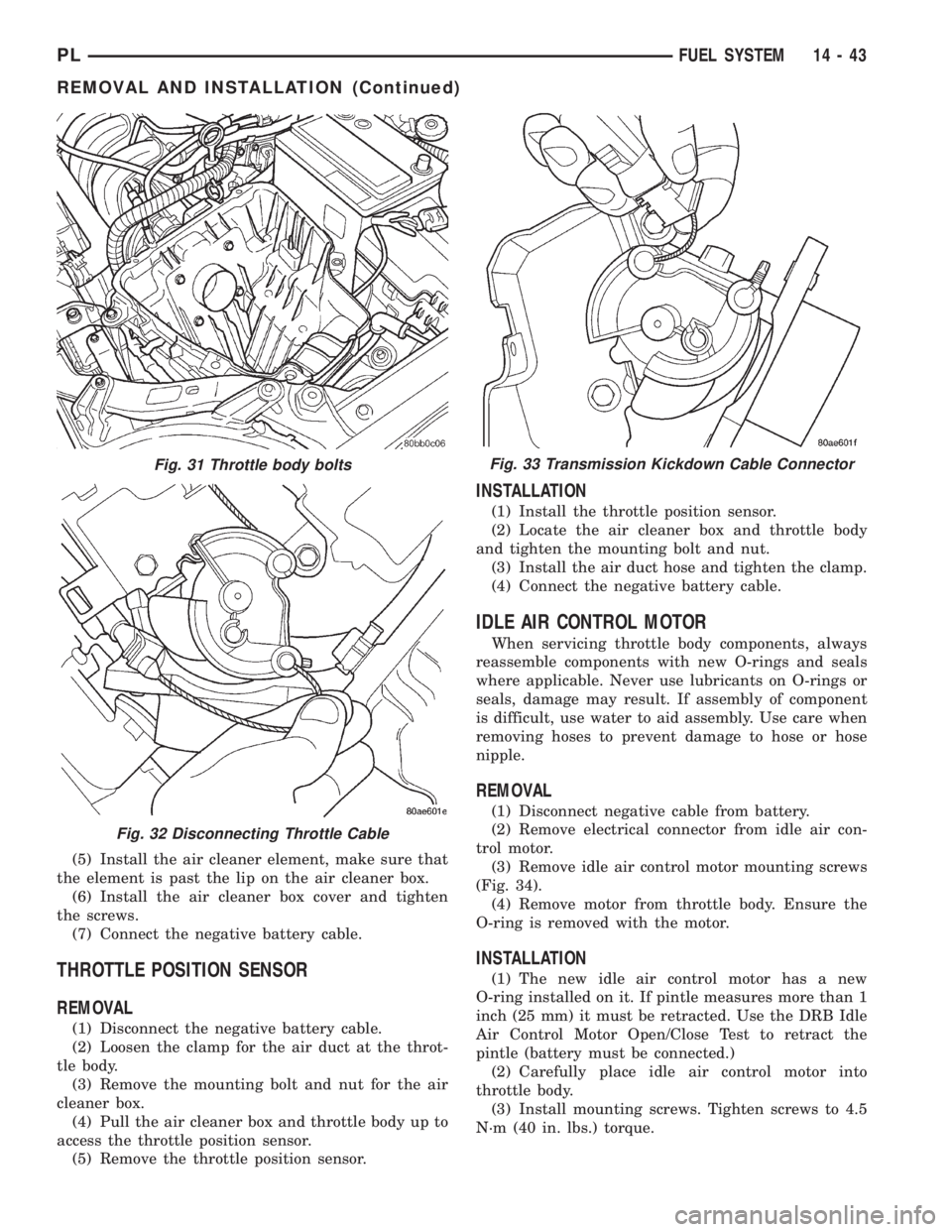
(5) Install the air cleaner element, make sure that
the element is past the lip on the air cleaner box.
(6) Install the air cleaner box cover and tighten
the screws.
(7) Connect the negative battery cable.
THROTTLE POSITION SENSOR
REMOVAL
(1) Disconnect the negative battery cable.
(2) Loosen the clamp for the air duct at the throt-
tle body.
(3) Remove the mounting bolt and nut for the air
cleaner box.
(4) Pull the air cleaner box and throttle body up to
access the throttle position sensor.
(5) Remove the throttle position sensor.
INSTALLATION
(1) Install the throttle position sensor.
(2) Locate the air cleaner box and throttle body
and tighten the mounting bolt and nut.
(3) Install the air duct hose and tighten the clamp.
(4) Connect the negative battery cable.
IDLE AIR CONTROL MOTOR
When servicing throttle body components, always
reassemble components with new O-rings and seals
where applicable. Never use lubricants on O-rings or
seals, damage may result. If assembly of component
is difficult, use water to aid assembly. Use care when
removing hoses to prevent damage to hose or hose
nipple.
REMOVAL
(1) Disconnect negative cable from battery.
(2) Remove electrical connector from idle air con-
trol motor.
(3) Remove idle air control motor mounting screws
(Fig. 34).
(4) Remove motor from throttle body. Ensure the
O-ring is removed with the motor.
INSTALLATION
(1) The new idle air control motor has a new
O-ring installed on it. If pintle measures more than 1
inch (25 mm) it must be retracted. Use the DRB Idle
Air Control Motor Open/Close Test to retract the
pintle (battery must be connected.)
(2) Carefully place idle air control motor into
throttle body.
(3) Install mounting screws. Tighten screws to 4.5
N´m (40 in. lbs.) torque.
Fig. 31 Throttle body bolts
Fig. 32 Disconnecting Throttle Cable
Fig. 33 Transmission Kickdown Cable Connector
PLFUEL SYSTEM 14 - 43
REMOVAL AND INSTALLATION (Continued)
Page 865 of 1285
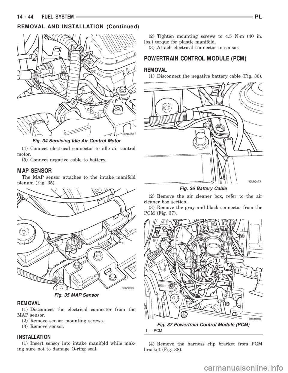
(4) Connect electrical connector to idle air control
motor.
(5) Connect negative cable to battery.
MAP SENSOR
The MAP sensor attaches to the intake manifold
plenum (Fig. 35).
REMOVAL
(1) Disconnect the electrical connector from the
MAP sensor.
(2) Remove sensor mounting screws.
(3) Remove sensor.
INSTALLATION
(1) Insert sensor into intake manifold while mak-
ing sure not to damage O-ring seal.(2) Tighten mounting screws to 4.5 N´m (40 in.
lbs.) torque for plastic manifold.
(3) Attach electrical connector to sensor.
POWERTRAIN CONTROL MODULE (PCM)
REMOVAL
(1) Disconnect the negative battery cable (Fig. 36).
(2) Remove the air cleaner box, refer to the air
cleaner box section.
(3) Remove the gray and black connector from the
PCM (Fig. 37).
(4) Remove the harness clip bracket from PCM
bracket (Fig. 38).
Fig. 34 Servicing Idle Air Control Motor
Fig. 35 MAP Sensor
Fig. 36 Battery Cable
Fig. 37 Powertrain Control Module (PCM)
1 ± PCM
14 - 44 FUEL SYSTEMPL
REMOVAL AND INSTALLATION (Continued)
Page 866 of 1285
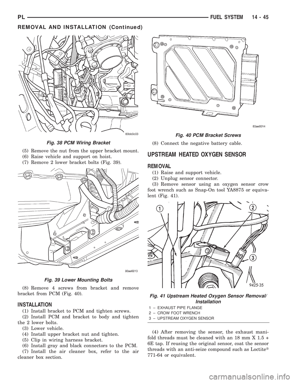
(5) Remove the nut from the upper bracket mount.
(6) Raise vehicle and support on hoist.
(7) Remove 2 lower bracket bolts (Fig. 39).
(8) Remove 4 screws from bracket and remove
bracket from PCM (Fig. 40).
INSTALLATION
(1) Install bracket to PCM and tighten screws.
(2) Install PCM and bracket to body and tighten
the 2 lower bolts.
(3) Lower vehicle.
(4) Install upper bracket nut and tighten.
(5) Clip in wiring harness bracket.
(6) Install gray and black connectors to the PCM.
(7) Install the air cleaner box, refer to the air
cleaner box section.(8) Connect the negative battery cable.
UPSTREAM HEATED OXYGEN SENSOR
REMOVAL
(1) Raise and support vehicle.
(2) Unplug sensor connector.
(3) Remove sensor using an oxygen sensor crow
foot wrench such as Snap-On tool YA8875 or equiva-
lent (Fig. 41).
(4) After removing the sensor, the exhaust mani-
fold threads must be cleaned with an 18 mm X 1.5 +
6E tap. If reusing the original sensor, coat the sensor
threads with an anti-seize compound such as Loctitet
771-64 or equivalent.
Fig. 38 PCM Wiring Bracket
Fig. 39 Lower Mounting Bolts
Fig. 40 PCM Bracket Screws
Fig. 41 Upstream Heated Oxygen Sensor Removal/
Installation
1 ± EXHAUST PIPE FLANGE
2 ± CROW FOOT WRENCH
3 ± UPSTREAM OXYGEN SENSOR
PLFUEL SYSTEM 14 - 45
REMOVAL AND INSTALLATION (Continued)
Page 867 of 1285
INSTALLATION
New sensors have compound on the threads and do
not require an additional coating.
(1) Install sensor using an oxygen sensor crow foot
wrench such as Snap-On tool YA8875 or equivalent
(Fig. 41). Tighten the sensor to 28 N´m (20 ft. lbs.)
torque.
(2) Plug sensor connector.
(3) Lower vehicle.
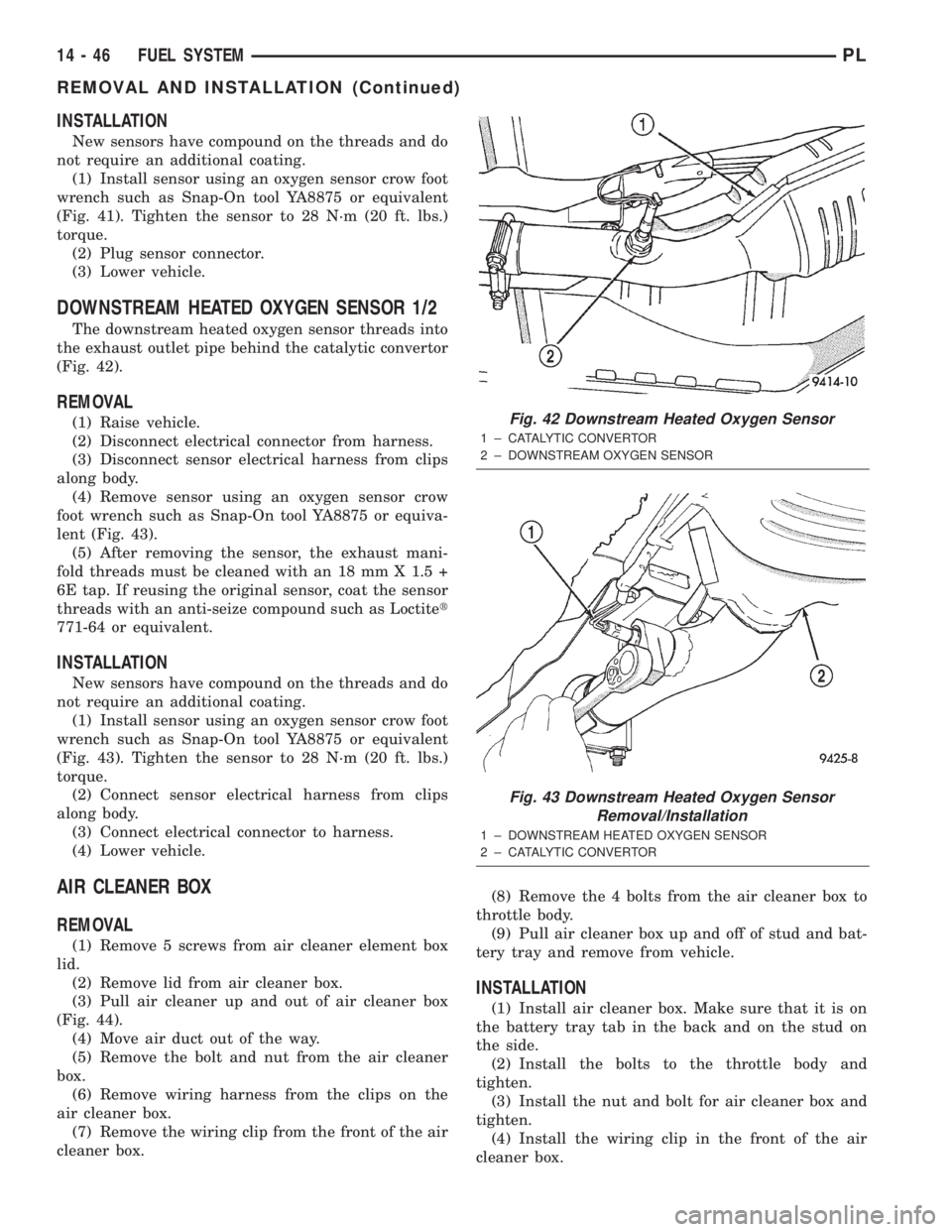
DOWNSTREAM HEATED OXYGEN SENSOR 1/2
The downstream heated oxygen sensor threads into
the exhaust outlet pipe behind the catalytic convertor
(Fig. 42).
REMOVAL
(1) Raise vehicle.
(2) Disconnect electrical connector from harness.
(3) Disconnect sensor electrical harness from clips
along body.
(4) Remove sensor using an oxygen sensor crow
foot wrench such as Snap-On tool YA8875 or equiva-
lent (Fig. 43).
(5) After removing the sensor, the exhaust mani-
fold threads must be cleaned with an 18 mm X 1.5 +
6E tap. If reusing the original sensor, coat the sensor
threads with an anti-seize compound such as Loctitet
771-64 or equivalent.
INSTALLATION
New sensors have compound on the threads and do
not require an additional coating.
(1) Install sensor using an oxygen sensor crow foot
wrench such as Snap-On tool YA8875 or equivalent
(Fig. 43). Tighten the sensor to 28 N´m (20 ft. lbs.)
torque.
(2) Connect sensor electrical harness from clips
along body.
(3) Connect electrical connector to harness.
(4) Lower vehicle.
AIR CLEANER BOX
REMOVAL
(1) Remove 5 screws from air cleaner element box
lid.
(2) Remove lid from air cleaner box.
(3) Pull air cleaner up and out of air cleaner box
(Fig. 44).
(4) Move air duct out of the way.
(5) Remove the bolt and nut from the air cleaner
box.
(6) Remove wiring harness from the clips on the
air cleaner box.
(7) Remove the wiring clip from the front of the air
cleaner box.(8) Remove the 4 bolts from the air cleaner box to
throttle body.
(9) Pull air cleaner box up and off of stud and bat-
tery tray and remove from vehicle.
INSTALLATION
(1) Install air cleaner box. Make sure that it is on
the battery tray tab in the back and on the stud on
the side.
(2) Install the bolts to the throttle body and
tighten.
(3) Install the nut and bolt for air cleaner box and
tighten.
(4) Install the wiring clip in the front of the air
cleaner box.
Fig. 42 Downstream Heated Oxygen Sensor
1 ± CATALYTIC CONVERTOR
2 ± DOWNSTREAM OXYGEN SENSOR
Fig. 43 Downstream Heated Oxygen Sensor
Removal/Installation
1 ± DOWNSTREAM HEATED OXYGEN SENSOR
2 ± CATALYTIC CONVERTOR
14 - 46 FUEL SYSTEMPL
REMOVAL AND INSTALLATION (Continued)
Page 868 of 1285
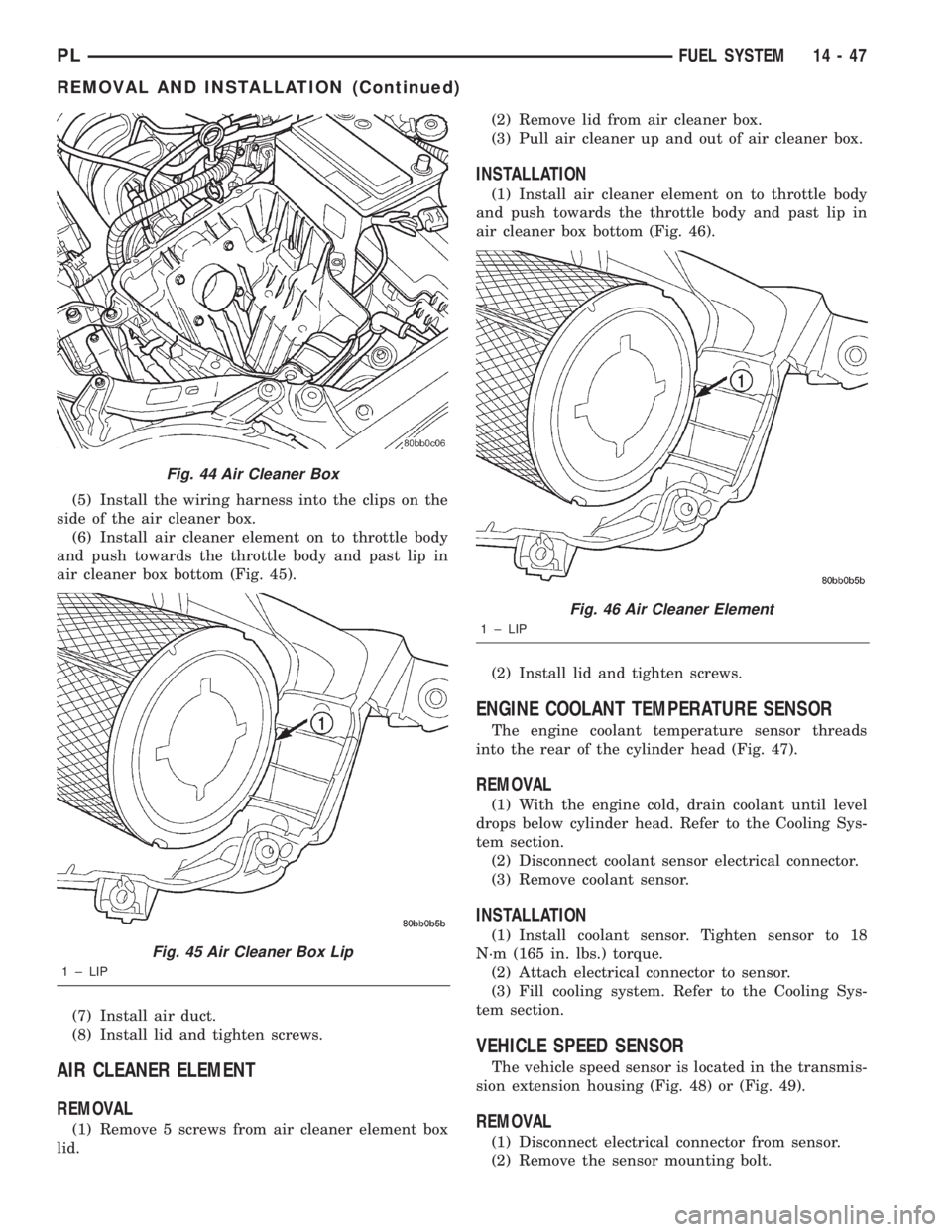
(5) Install the wiring harness into the clips on the
side of the air cleaner box.
(6) Install air cleaner element on to throttle body
and push towards the throttle body and past lip in
air cleaner box bottom (Fig. 45).
(7) Install air duct.
(8) Install lid and tighten screws.
AIR CLEANER ELEMENT
REMOVAL
(1) Remove 5 screws from air cleaner element box
lid.(2) Remove lid from air cleaner box.
(3) Pull air cleaner up and out of air cleaner box.
INSTALLATION
(1) Install air cleaner element on to throttle body
and push towards the throttle body and past lip in
air cleaner box bottom (Fig. 46).
(2) Install lid and tighten screws.
ENGINE COOLANT TEMPERATURE SENSOR
The engine coolant temperature sensor threads
into the rear of the cylinder head (Fig. 47).
REMOVAL
(1) With the engine cold, drain coolant until level
drops below cylinder head. Refer to the Cooling Sys-
tem section.
(2) Disconnect coolant sensor electrical connector.
(3) Remove coolant sensor.
INSTALLATION
(1) Install coolant sensor. Tighten sensor to 18
N´m (165 in. lbs.) torque.
(2) Attach electrical connector to sensor.
(3) Fill cooling system. Refer to the Cooling Sys-
tem section.
VEHICLE SPEED SENSOR
The vehicle speed sensor is located in the transmis-
sion extension housing (Fig. 48) or (Fig. 49).
REMOVAL
(1) Disconnect electrical connector from sensor.
(2) Remove the sensor mounting bolt.
Fig. 44 Air Cleaner Box
Fig. 45 Air Cleaner Box Lip
1 ± LIP
Fig. 46 Air Cleaner Element
1 ± LIP
PLFUEL SYSTEM 14 - 47
REMOVAL AND INSTALLATION (Continued)