2000 DODGE NEON sensor
[x] Cancel search: sensorPage 757 of 1285
INSPECT CYLINDER HEAD FOR THE FOLLOWING:
NOTE:
²Check oil feed holes for blockage.
²Inspect cylinder head camshaft bearings for
wear, Refer to Cylinder Head, Inspection and Clean-
ing.
²Check camshaft bearing journals for scratches
and worn areas. If light scratches are present, they
may be removed with 400 grit sand paper. If deep
scratches are present, replace the camshaft and
check the cylinder head for damage. Replace the
cylinder head if worn or damaged. Check the lobes
for pitting and wear. If the lobes show signs of
wear, check the corresponding rocker arm roller for
wear or damage. Replace rocker arm/hydraulic lash
adjuster if worn or damaged. If lobes show signs of
pitting on the nose, flank or base circle; replace the
camshaft.
INSTALLATION
(1) Lubricate the camshaft journals with oil and
install camshaftwithoutrocker arm assemblies
installed.
(2) Install camshaft target magnet into the end of
the camshaft. Tighten mounting screw to 3.4 N´m (30
in. lbs.).
(3) Install camshaft position sensor and tighten
mounting screws to 9 N´m (80 in. lbs.).
(4) Measure camshaft end play using the following
procedure:
(a) Mount dial indicator C-3339 or equivalent, to
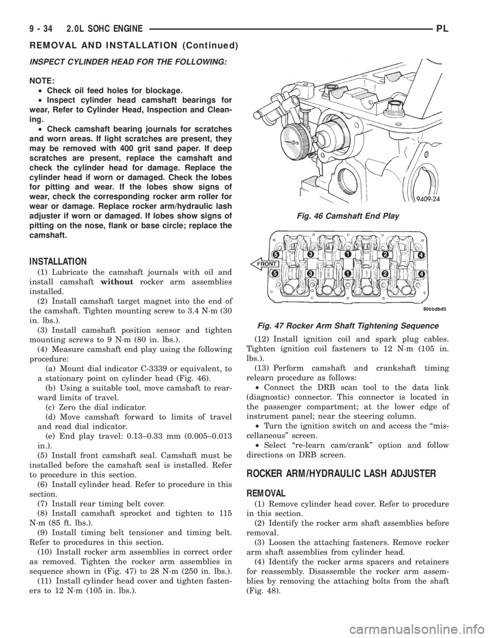
a stationary point on cylinder head (Fig. 46).
(b) Using a suitable tool, move camshaft to rear-
ward limits of travel.
(c) Zero the dial indicator.
(d) Move camshaft forward to limits of travel
and read dial indicator.
(e) End play travel: 0.13±0.33 mm (0.005±0.013
in.).
(5) Install front camshaft seal. Camshaft must be
installed before the camshaft seal is installed. Refer
to procedure in this section.
(6) Install cylinder head. Refer to procedure in this
section.
(7) Install rear timing belt cover.
(8) Install camshaft sprocket and tighten to 115
N´m (85 ft. lbs.).
(9) Install timing belt tensioner and timing belt.
Refer to procedures in this section.
(10) Install rocker arm assemblies in correct order
as removed. Tighten the rocker arm assemblies in
sequence shown in (Fig. 47) to 28 N´m (250 in. lbs.).
(11) Install cylinder head cover and tighten fasten-
ers to 12 N´m (105 in. lbs.).(12) Install ignition coil and spark plug cables.
Tighten ignition coil fasteners to 12 N´m (105 in.
lbs.).
(13) Perform camshaft and crankshaft timing
relearn procedure as follows:
²Connect the DRB scan tool to the data link
(diagnostic) connector. This connector is located in
the passenger compartment; at the lower edge of
instrument panel; near the steering column.
²Turn the ignition switch on and access the ªmis-
cellaneousº screen.
²Select ªre-learn cam/crankº option and follow
directions on DRB screen.
ROCKER ARM/HYDRAULIC LASH ADJUSTER
REMOVAL
(1) Remove cylinder head cover. Refer to procedure
in this section.
(2) Identify the rocker arm shaft assemblies before
removal.
(3) Loosen the attaching fasteners. Remove rocker
arm shaft assemblies from cylinder head.
(4) Identify the rocker arms spacers and retainers
for reassembly. Disassemble the rocker arm assem-
blies by removing the attaching bolts from the shaft
(Fig. 48).
Fig. 46 Camshaft End Play
Fig. 47 Rocker Arm Shaft Tightening Sequence
9 - 34 2.0L SOHC ENGINEPL
REMOVAL AND INSTALLATION (Continued)
Page 760 of 1285
CYLINDER HEAD
REMOVAL
(1) Perform fuel system pressure release procedure
before attempting any repairs.Refer to Group 14,
Fuel System
(2) Disconnect negative battery cable.
(3) Remove power steering/air conditioning drive
belt. Refer to Group 7, Cooling System Accessory
Drive for procedure.
(4) Raise vehicle.
(5) Drain cooling system. Refer to Group 7, Cooling
System.
(6) Remove exhaust pipe from manifold.
(7) Remove right front wheel.
(8) Remove right side splash shield.
(9) Remove generator belt. Refer to Group 7, Cool-
ing System Accessory Drive Belts for procedure.
(10) Remove crankshaft damper. Refer to proce-
dure in this section.
(11) Remove lower torque strut.
(12) Lower vehicle and remove upper torque strut.
(13) Remove ground strap and power steering hose
support clip from engine mount bracket.
(14) Remove power steering pump assembly and
set aside.
(15) Support engine from beneath with a suitable
jack.
(16) Remove right side engine mount to bracket
through bolt.
(17) Remove the lower engine mount bracket bolt.
Raise engine slightly and remove the upper engine
mount bracket bolts.(18) Remove engine mount bracket. This procedure
may require additional raising/lowering of engine
until bracket will clear engine components.
(19) Remove front timing belt cover.
(20) Rotate engine until timing marks are aligned.
(21) Remove timing belt and tensioner. Refer to
procedures in this section.
(22) Remove camshaft sprocket. Refer to proce-
dures in this section.
(23) Remove rear timing belt cover.
(24) Disconnect fuel line at fuel rail.
(25) Remove coolant recovery container.
(26) Remove ground wire to cylinder head.
(27) Remove upper radiator hose.
(28) Remove intake manifold. Refer to procedure
in this section.
(29) Disconnect ignition coil electrical connector.
Remove coil pack and spark plug cables from engine.
(30) Remove Crankcase Closed Ventilation (CCV)
hose from cylinder head cover.
(31) Disconnect cam sensor and coolant tempera-
ture electrical connectors.
(32) Remove heater tube to cylinder head attach-
ing fasteners.
(33) Remove heater hose from thermostat housing
connector.
(34) Remove cylinder head cover.
(35) Remove cylinder head bolts.
(36) Remove cylinder head and gasket (Fig. 55).
PL2.0L SOHC ENGINE 9 - 37
REMOVAL AND INSTALLATION (Continued)
Page 762 of 1285
(2) Apply MopartGasket Sealant (aerosol can) to
both sides of the new cylinder head gasket.
(3) Position a new cylinder head gasket on the
locating dowels.
(4) Position crankshaft sprocket to TDC, then
rotate crankshaft until mark is three teeth before
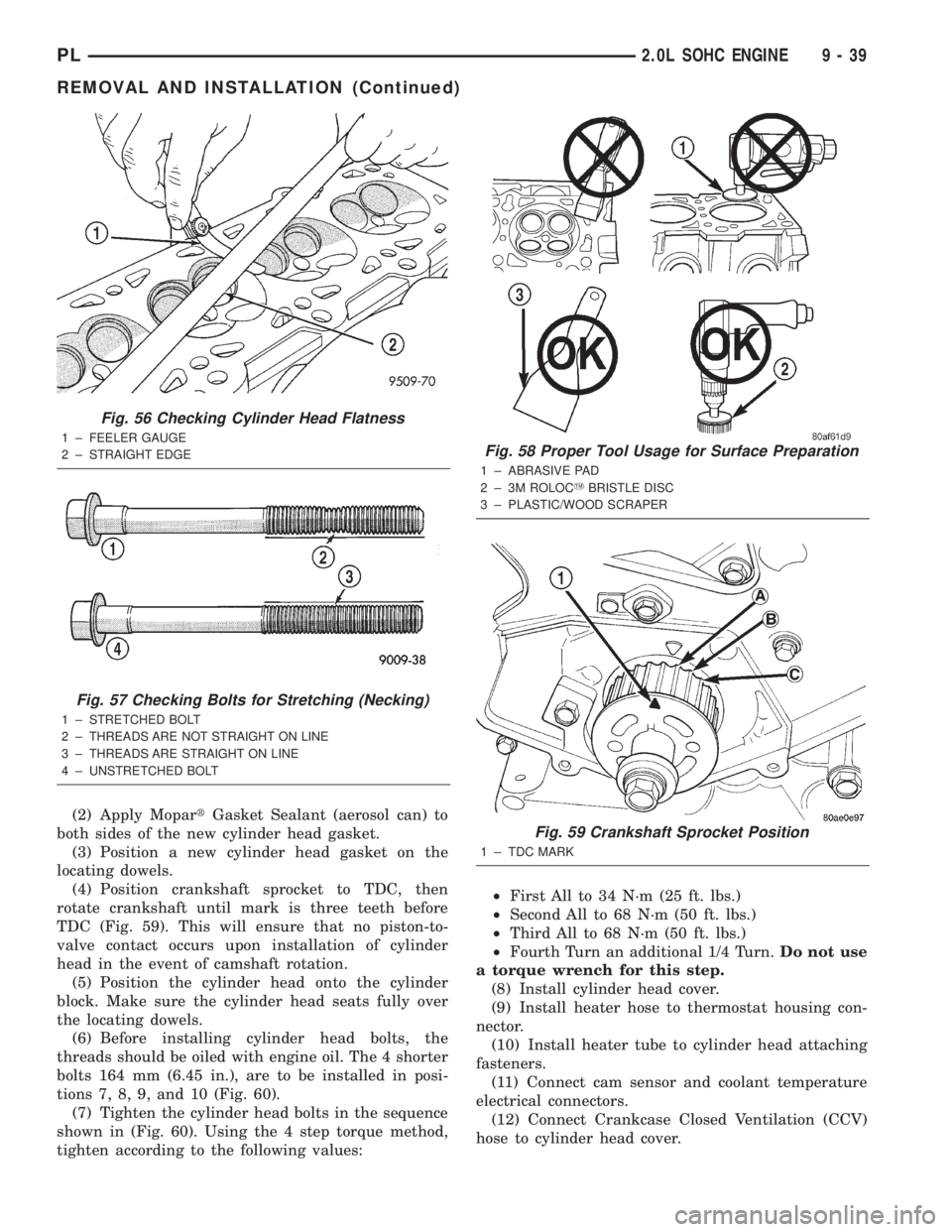
TDC (Fig. 59). This will ensure that no piston-to-
valve contact occurs upon installation of cylinder
head in the event of camshaft rotation.
(5) Position the cylinder head onto the cylinder
block. Make sure the cylinder head seats fully over
the locating dowels.
(6) Before installing cylinder head bolts, the
threads should be oiled with engine oil. The 4 shorter
bolts 164 mm (6.45 in.), are to be installed in posi-
tions 7, 8, 9, and 10 (Fig. 60).
(7) Tighten the cylinder head bolts in the sequence
shown in (Fig. 60). Using the 4 step torque method,
tighten according to the following values:²First All to 34 N´m (25 ft. lbs.)
²Second All to 68 N´m (50 ft. lbs.)
²Third All to 68 N´m (50 ft. lbs.)
²Fourth Turn an additional 1/4 Turn.Do not use
a torque wrench for this step.
(8) Install cylinder head cover.
(9) Install heater hose to thermostat housing con-
nector.
(10) Install heater tube to cylinder head attaching
fasteners.
(11) Connect cam sensor and coolant temperature
electrical connectors.
(12) Connect Crankcase Closed Ventilation (CCV)
hose to cylinder head cover.
Fig. 56 Checking Cylinder Head Flatness
1 ± FEELER GAUGE
2 ± STRAIGHT EDGE
Fig. 57 Checking Bolts for Stretching (Necking)
1 ± STRETCHED BOLT
2 ± THREADS ARE NOT STRAIGHT ON LINE
3 ± THREADS ARE STRAIGHT ON LINE
4 ± UNSTRETCHED BOLT
Fig. 58 Proper Tool Usage for Surface Preparation
1 ± ABRASIVE PAD
2 ± 3M ROLOCYBRISTLE DISC
3 ± PLASTIC/WOOD SCRAPER
Fig. 59 Crankshaft Sprocket Position
1 ± TDC MARK
PL2.0L SOHC ENGINE 9 - 39
REMOVAL AND INSTALLATION (Continued)
Page 775 of 1285
CRANKSHAFT
REMOVAL
(1) Remove engine assembly. Refer to procedure in
this section.
(2) Remove structural collar from oil pan to tran-
saxle housing.
(3) Separate transaxle from engine.
(4) Remove drive plate/flywheel.
(5) Remove crankshaft rear oil seal. Refer to pro-
cedure in this section.
(6) Mount engine on a suitable repair stand.
(7) Remove crankshaft damper, timing belt, and
tensioner. Refer to procedures in this section.
(8) Remove camshaft sprocket and rear timing belt
cover. Refer to procedures in this section.
(9) Remove crankshaft sprocket. Refer to proce-
dure in this section.(10) Remove lower torque strut/air conditioning
compressor mounting bracket from engine (Fig. 95).
(11) Remove oil filter and adapter.
(12) Remove oil pan.
(13) Remove oil pump pick-up tube.
(14) Remove oil pump.
(15) Remove crankshaft position sensor.
(16) Using a permanent ink or paint marker, iden-
tify cylinder number on each connecting rod cap.
CAUTION: DO NOT use a number stamp or a punch
to mark connecting rods. Damage to connecting
rod could occur.
(17) Remove all connecting rod bolts and caps.
Care should be taken not to damage the fracture rod
and cap surfaces.
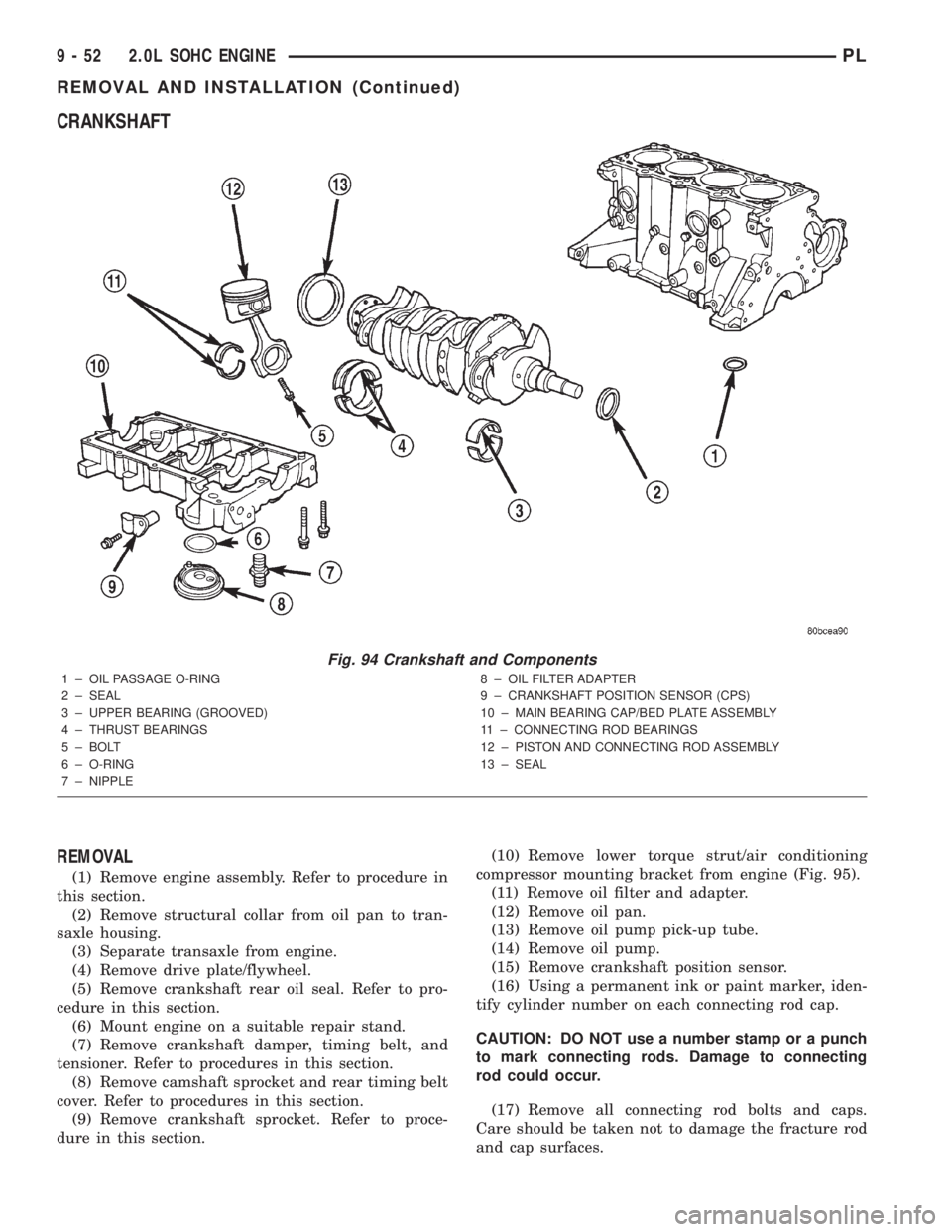
Fig. 94 Crankshaft and Components
1 ± OIL PASSAGE O-RING
2 ± SEAL
3 ± UPPER BEARING (GROOVED)
4 ± THRUST BEARINGS
5 ± BOLT
6 ± O-RING
7 ± NIPPLE8 ± OIL FILTER ADAPTER
9 ± CRANKSHAFT POSITION SENSOR (CPS)
10 ± MAIN BEARING CAP/BED PLATE ASSEMBLY
11 ± CONNECTING ROD BEARINGS
12 ± PISTON AND CONNECTING ROD ASSEMBLY
13 ± SEAL
9 - 52 2.0L SOHC ENGINEPL
REMOVAL AND INSTALLATION (Continued)
Page 794 of 1285
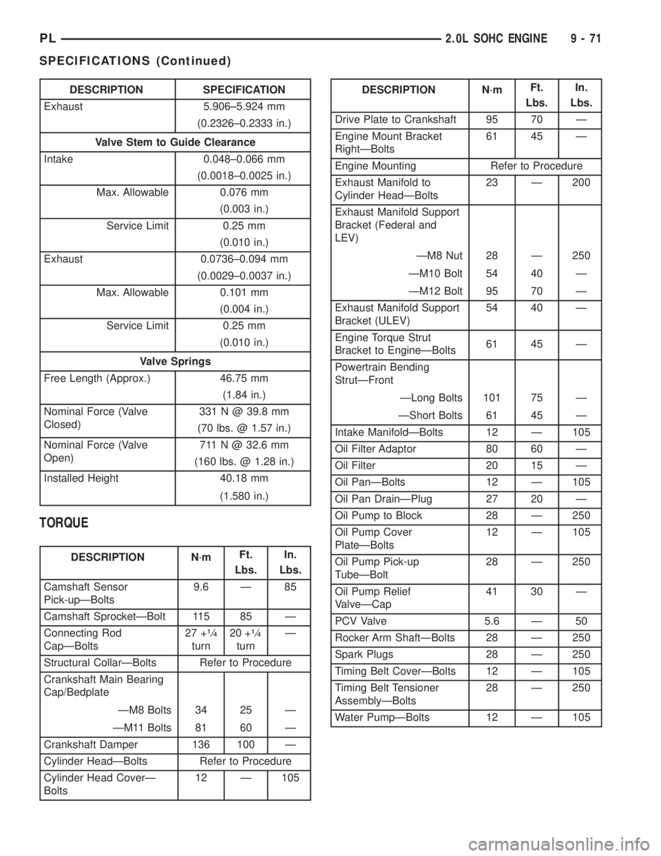
DESCRIPTION SPECIFICATION
Exhaust 5.906±5.924 mm
(0.2326±0.2333 in.)
Valve Stem to Guide Clearance
Intake 0.048±0.066 mm
(0.0018±0.0025 in.)
Max. Allowable 0.076 mm
(0.003 in.)
Service Limit 0.25 mm
(0.010 in.)
Exhaust 0.0736±0.094 mm
(0.0029±0.0037 in.)
Max. Allowable 0.101 mm
(0.004 in.)
Service Limit 0.25 mm
(0.010 in.)
Valve Springs
Free Length (Approx.) 46.75 mm
(1.84 in.)
Nominal Force (Valve
Closed)331 N @ 39.8 mm
(70 lbs. @ 1.57 in.)
Nominal Force (Valve
Open)711 N @ 32.6 mm
(160 lbs. @ 1.28 in.)
Installed Height 40.18 mm
(1.580 in.)
TORQUE
DESCRIPTION N´mFt.
Lbs.In.
Lbs.
Camshaft Sensor
Pick-upÐBolts9.6 Ð 85
Camshaft SprocketÐBolt 115 85 Ð
Connecting Rod
CapÐBolts27 +
1¤4
turn20 +
1¤4
turnÐ
Structural CollarÐBolts Refer to Procedure
Crankshaft Main Bearing
Cap/Bedplate
ÐM8 Bolts 34 25 Ð
ÐM11 Bolts 81 60 Ð
Crankshaft Damper 136 100 Ð
Cylinder HeadÐBolts Refer to Procedure
Cylinder Head CoverÐ
Bolts12 Ð 105
DESCRIPTION N´mFt.
Lbs.In.
Lbs.
Drive Plate to Crankshaft 95 70 Ð
Engine Mount Bracket
RightÐBolts61 45 Ð
Engine Mounting Refer to Procedure
Exhaust Manifold to
Cylinder HeadÐBolts23 Ð 200
Exhaust Manifold Support
Bracket (Federal and
LEV)
ÐM8 Nut 28 Ð 250
ÐM10 Bolt 54 40 Ð
ÐM12 Bolt 95 70 Ð
Exhaust Manifold Support
Bracket (ULEV)54 40 Ð
Engine Torque Strut
Bracket to EngineÐBolts61 45 Ð
Powertrain Bending
StrutÐFront
ÐLong Bolts 101 75 Ð
ÐShort Bolts 61 45 Ð
Intake ManifoldÐBolts 12 Ð 105
Oil Filter Adaptor 80 60 Ð
Oil Filter 20 15 Ð
Oil PanÐBolts 12 Ð 105
Oil Pan DrainÐPlug 27 20 Ð
Oil Pump to Block 28 Ð 250
Oil Pump Cover
PlateÐBolts12 Ð 105
Oil Pump Pick-up
TubeÐBolt28 Ð 250
Oil Pump Relief
ValveÐCap41 30 Ð
PCV Valve 5.6 Ð 50
Rocker Arm ShaftÐBolts 28 Ð 250
Spark Plugs 28 Ð 250
Timing Belt CoverÐBolts 12 Ð 105
Timing Belt Tensioner
AssemblyÐBolts28 Ð 250
Water PumpÐBolts 12 Ð 105
PL2.0L SOHC ENGINE 9 - 71
SPECIFICATIONS (Continued)
Page 799 of 1285
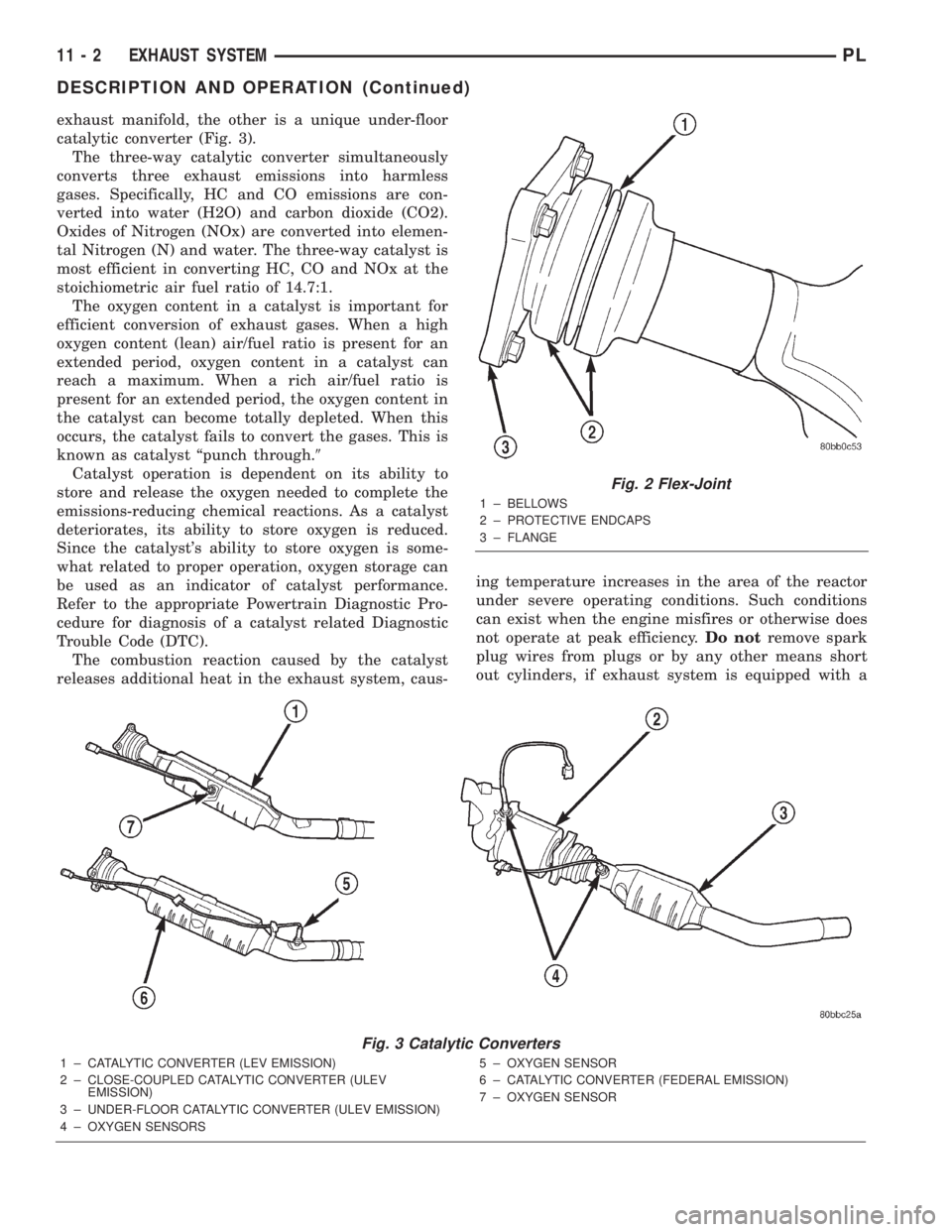
exhaust manifold, the other is a unique under-floor
catalytic converter (Fig. 3).
The three-way catalytic converter simultaneously
converts three exhaust emissions into harmless
gases. Specifically, HC and CO emissions are con-
verted into water (H2O) and carbon dioxide (CO2).
Oxides of Nitrogen (NOx) are converted into elemen-
tal Nitrogen (N) and water. The three-way catalyst is
most efficient in converting HC, CO and NOx at the
stoichiometric air fuel ratio of 14.7:1.
The oxygen content in a catalyst is important for
efficient conversion of exhaust gases. When a high
oxygen content (lean) air/fuel ratio is present for an
extended period, oxygen content in a catalyst can
reach a maximum. When a rich air/fuel ratio is
present for an extended period, the oxygen content in
the catalyst can become totally depleted. When this
occurs, the catalyst fails to convert the gases. This is
known as catalyst ªpunch through.9
Catalyst operation is dependent on its ability to
store and release the oxygen needed to complete the
emissions-reducing chemical reactions. As a catalyst
deteriorates, its ability to store oxygen is reduced.
Since the catalyst's ability to store oxygen is some-
what related to proper operation, oxygen storage can
be used as an indicator of catalyst performance.
Refer to the appropriate Powertrain Diagnostic Pro-
cedure for diagnosis of a catalyst related Diagnostic
Trouble Code (DTC).
The combustion reaction caused by the catalyst
releases additional heat in the exhaust system, caus-ing temperature increases in the area of the reactor
under severe operating conditions. Such conditions
can exist when the engine misfires or otherwise does
not operate at peak efficiency.Do notremove spark
plug wires from plugs or by any other means short
out cylinders, if exhaust system is equipped with a
Fig. 2 Flex-Joint
1 ± BELLOWS
2 ± PROTECTIVE ENDCAPS
3 ± FLANGE
Fig. 3 Catalytic Converters
1 ± CATALYTIC CONVERTER (LEV EMISSION)
2 ± CLOSE-COUPLED CATALYTIC CONVERTER (ULEV
EMISSION)
3 ± UNDER-FLOOR CATALYTIC CONVERTER (ULEV EMISSION)
4 ± OXYGEN SENSORS5 ± OXYGEN SENSOR
6 ± CATALYTIC CONVERTER (FEDERAL EMISSION)
7 ± OXYGEN SENSOR
11 - 2 EXHAUST SYSTEMPL
DESCRIPTION AND OPERATION (Continued)
Page 804 of 1285
CATALYTIC CONVERTER
REMOVAL
WARNING: THE NORMAL OPERATING TEMPERA-
TURE OF THE EXHAUST SYSTEM IS VERY HIGH.
THEREFORE, NEVER ATTEMPT TO SERVICE ANY
PART OF THE EXHAUST SYSTEM UNTIL IT IS
COOLED. SPECIAL CARE SHOULD BE TAKEN
WHEN WORKING NEAR THE CATALYTIC CON-
VERTER. THE TEMPERATURE OF THE CONVERTER
RISES TO A HIGH LEVEL AFTER A SHORT PERIOD
OF ENGINE OPERATION TIME.
NOTE: Vehicles equipped with the ULEV emission
package are equipped with an additional catalytic
converter that is integral to the exhaust manifold.
Refer to Exhaust Manifold in Group 9, Engine for
procedure.
(1) Remove muffler and exhaust pipe. Refer to pro-
cedure in this section.
(2) Disconnect downstream oxygen sensor electri-
cal connector.
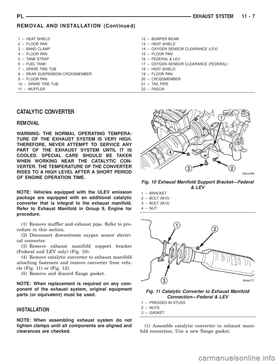
(3) Remove exhaust manifold support bracket
(Federal and LEV only) (Fig. 10).
(4) Remove catalytic converter to exhaust manifold
attaching fasteners and remove converter from vehi-
cle (Fig. 11) or (Fig. 12).
(5) Remove and discard flange gasket.
NOTE: When replacement is required on any com-
ponent of the exhaust system, original equipment
parts (or equivalent) must be used.
INSTALLATION
NOTE: When assembling exhaust system do not
tighten clamps until all components are aligned and
clearances are checked.(1) Assemble catalytic converter to exhaust mani-
fold connection. Use a new flange gasket.
1 ± HEAT SHIELD
2 ± FLOOR PAN
3 ± BAND CLAMP
4 ± FLOOR PAN
5 ± TANK STRAP
6 ± FUEL TANK
7 ± SPARE TIRE TUB
8 ± REAR SUSPENSION CROSSMEMBER
9 ± FLOOR PAN
10 ± SPARE TIRE TUB
11 ± MUFFLER12 ± BUMPER BEAM
13 ± HEAT SHIELD
14 ± OXYGEN SENSOR CLEARANCE (LEV)
15 ± FLOOR PAN
16 ± FEDERAL & LEV
17 ± OXYGEN SENSOR CLEARANCE (FEDERAL)
18 ± HEAT SHIELD
19 ± FLOOR PAN
20 ± CROSSMEMBER
21 ± TAIL PIPE
22 ± FASCIA
Fig. 10 Exhaust Manifold Support BracketÐFederal
& LEV
1 ± BRACKET
2 ± BOLT (M10)
3 ± BOLT (M12)
4 ± NUT
Fig. 11 Catalytic Converter to Exhaust Manifold
ConnectionÐFederal & LEV
1 ± PRESSED-IN STUDS
2 ± NUTS
3 ± GASKET
PLEXHAUST SYSTEM 11 - 7
REMOVAL AND INSTALLATION (Continued)
Page 805 of 1285
(2) Install exhaust manifold support bracket (Fed-
eral and LEV only). Tighten M10 bolt to 54 N´m (40
ft. lbs.), M12 bolt to 95 N´m (70 ft. lbs.), and nut to
28 N´m (250 in. lbs.).
(3) Install bolt attaching manifold support bracket
to the heat shield (Federal and LEV only). Tighten
bolt to 28 N´m (250 in. lbs.).
(4) Assemble muffler and exhaust pipe to catalytic
converter. Install muffler and pipe support isolators
to the underbody.
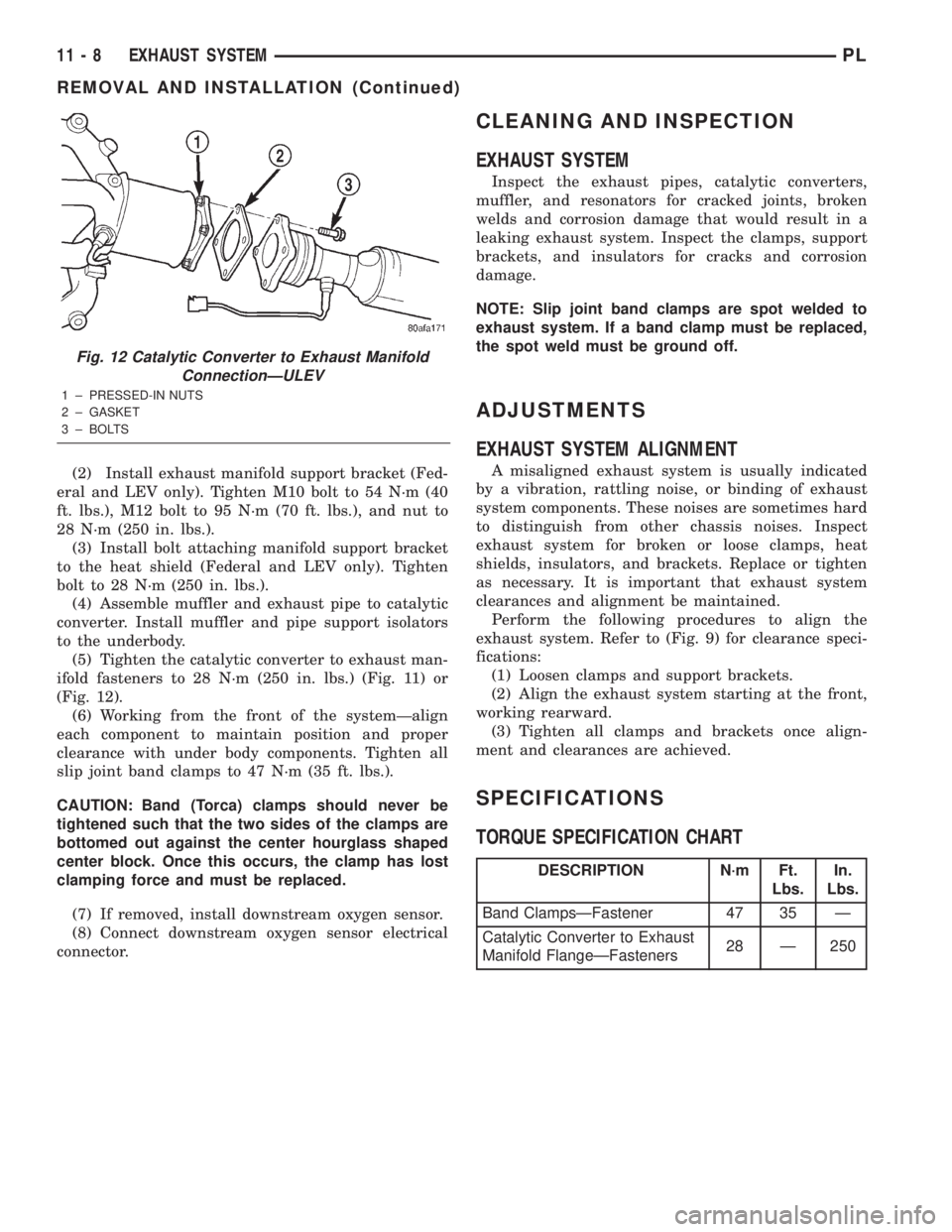
(5) Tighten the catalytic converter to exhaust man-
ifold fasteners to 28 N´m (250 in. lbs.) (Fig. 11) or
(Fig. 12).
(6) Working from the front of the systemÐalign
each component to maintain position and proper
clearance with under body components. Tighten all
slip joint band clamps to 47 N´m (35 ft. lbs.).
CAUTION: Band (Torca) clamps should never be
tightened such that the two sides of the clamps are
bottomed out against the center hourglass shaped
center block. Once this occurs, the clamp has lost
clamping force and must be replaced.
(7) If removed, install downstream oxygen sensor.
(8) Connect downstream oxygen sensor electrical
connector.
CLEANING AND INSPECTION
EXHAUST SYSTEM
Inspect the exhaust pipes, catalytic converters,
muffler, and resonators for cracked joints, broken
welds and corrosion damage that would result in a
leaking exhaust system. Inspect the clamps, support
brackets, and insulators for cracks and corrosion
damage.
NOTE: Slip joint band clamps are spot welded to
exhaust system. If a band clamp must be replaced,
the spot weld must be ground off.
ADJUSTMENTS
EXHAUST SYSTEM ALIGNMENT
A misaligned exhaust system is usually indicated
by a vibration, rattling noise, or binding of exhaust
system components. These noises are sometimes hard
to distinguish from other chassis noises. Inspect
exhaust system for broken or loose clamps, heat
shields, insulators, and brackets. Replace or tighten
as necessary. It is important that exhaust system
clearances and alignment be maintained.
Perform the following procedures to align the
exhaust system. Refer to (Fig. 9) for clearance speci-
fications:
(1) Loosen clamps and support brackets.
(2) Align the exhaust system starting at the front,
working rearward.
(3) Tighten all clamps and brackets once align-
ment and clearances are achieved.
SPECIFICATIONS
TORQUE SPECIFICATION CHART
Fig. 12 Catalytic Converter to Exhaust Manifold
ConnectionÐULEV
1 ± PRESSED-IN NUTS
2 ± GASKET
3 ± BOLTS
DESCRIPTION N´m Ft.
Lbs.In.
Lbs.
Band ClampsÐFastener 47 35 Ð
Catalytic Converter to Exhaust
Manifold FlangeÐFasteners28 Ð 250
11 - 8 EXHAUST SYSTEMPL
REMOVAL AND INSTALLATION (Continued)