2000 DODGE NEON sensor
[x] Cancel search: sensorPage 710 of 1285
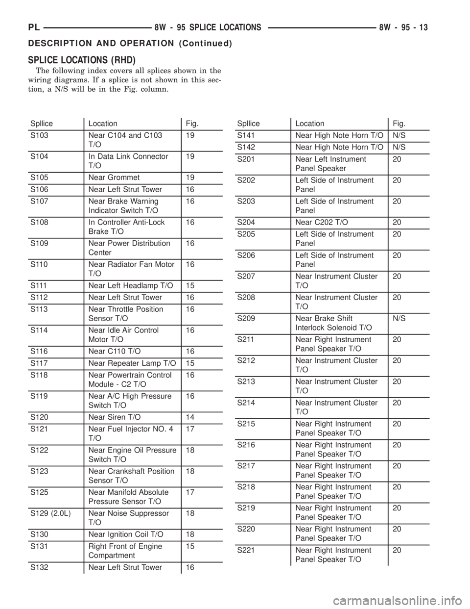
SPLICE LOCATIONS (RHD)
The following index covers all splices shown in the
wiring diagrams. If a splice is not shown in this sec-
tion, a N/S will be in the Fig. column.
Spllice Location Fig.
S103 Near C104 and C103
T/O19
S104 In Data Link Connector
T/O19
S105 Near Grommet 19
S106 Near Left Strut Tower 16
S107 Near Brake Warning
Indicator Switch T/O16
S108 In Controller Anti-Lock
Brake T/O16
S109 Near Power Distribution
Center16
S110 Near Radiator Fan Motor
T/O16
S111 Near Left Headlamp T/O 15
S112 Near Left Strut Tower 16
S113 Near Throttle Position
Sensor T/O16
S114 Near Idle Air Control
Motor T/O16
S116 Near C110 T/O 16
S117 Near Repeater Lamp T/O 15
S118 Near Powertrain Control
Module - C2 T/O16
S119 Near A/C High Pressure
Switch T/O16
S120 Near Siren T/O 14
S121 Near Fuel Injector NO. 4
T/O17
S122 Near Engine Oil Pressure
Switch T/O18
S123 Near Crankshaft Position
Sensor T/O18
S125 Near Manifold Absolute
Pressure Sensor T/O17
S129 (2.0L) Near Noise Suppressor
T/O18
S130 Near Ignition Coil T/O 18
S131 Right Front of Engine
Compartment15
S132 Near Left Strut Tower 16Spllice Location Fig.
S141 Near High Note Horn T/O N/S
S142 Near High Note Horn T/O N/S
S201 Near Left Instrument
Panel Speaker20
S202 Left Side of Instrument
Panel20
S203 Left Side of Instrument
Panel20
S204 Near C202 T/O 20
S205 Left Side of Instrument
Panel20
S206 Left Side of Instrument
Panel20
S207 Near Instrument Cluster
T/O20
S208 Near Instrument Cluster
T/O20
S209 Near Brake Shift
Interlock Solenoid T/ON/S
S211 Near Right Instrument
Panel Speaker T/O20
S212 Near Instrument Cluster
T/O20
S213 Near Instrument Cluster
T/O20
S214 Near Instrument Cluster
T/O20
S215 Near Right Instrument
Panel Speaker T/O20
S216 Near Right Instrument
Panel Speaker T/O20
S217 Near Right Instrument
Panel Speaker T/O20
S218 Near Right Instrument
Panel Speaker T/O20
S219 Near Right Instrument
Panel Speaker T/O20
S220 Near Right Instrument
Panel Speaker T/O20
S221 Near Right Instrument
Panel Speaker T/O20
PL8W - 95 SPLICE LOCATIONS 8W - 95 - 13
DESCRIPTION AND OPERATION (Continued)
Page 739 of 1285
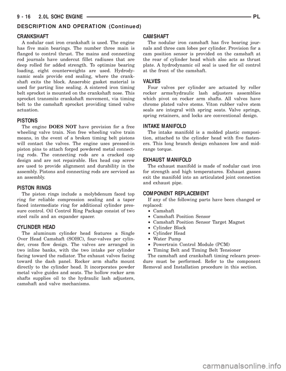
CRANKSHAFT
A nodular cast iron crankshaft is used. The engine
has five main bearings. The number three main is
flanged to control thrust. The mains and connecting
rod journals have undercut fillet radiuses that are
deep rolled for added strength. To optimize bearing
loading, eight counterweights are used. Hydrody-
namic seals provide end sealing, where the crank-
shaft exits the block. Anaerobic gasket material is
used for parting line sealing. A sintered iron timing
belt sprocket is mounted on the crankshaft nose. This
sprocket transmits crankshaft movement, via timing
belt to the camshaft sprocket providing timed valve
actuation.
PISTONS
The engineDOES NOThave provision for a free
wheeling valve train. Non free wheeling valve train
means, in the event of a broken timing belt pistons
will contact the valves. The engine uses pressed-in
piston pins to attach forged powdered metal connect-
ing rods. The connecting rods are a cracked cap
design and are not repairable. Hex head cap screw
are used to provide alignment and durability in the
assembly. Pistons and connecting rods are serviced as
an assembly.
PISTON RINGS
The piston rings include a molybdenum faced top
ring for reliable compression sealing and a taper
faced intermediate ring for additional cylinder pres-
sure control. Oil Control Ring Package consist of two
steel rails and an expander spacer.
CYLINDER HEAD
The aluminum cylinder head features a Single
Over Head Camshaft (SOHC), four-valves per cylin-
der, cross flow design. The valves are arranged in
two inline banks, with the two intake per cylinder
facing toward the radiator. The exhaust valves facing
toward the dash panel. Rocker arm shafts mount
directly to the cylinder head. It incorporates powder
metal valve guides and seats. The hollow rocker arm
shafts supplies oil to the hydraulic lash adjusters,
camshaft and valve mechanisms.
CAMSHAFT
The nodular iron camshaft has five bearing jour-
nals and three cam lobes per cylinder. Provision for a
cam position sensor is provided on the camshaft at
the rear of cylinder head which also acts as thrust
plate. A hydrodynamic oil seal is used for oil control
at the front of the camshaft.
VALVES
Four valves per cylinder are actuated by roller
rocker arms/hydraulic lash adjusters assemblies
which pivot on rocker arm shafts. All valves have
chrome plated valve stems. Viton rubber valve stem
seals are integral with spring seats. Valve springs,
spring retainers, and locks are conventional design.
INTAKE MANIFOLD
The intake manifold is a molded plastic composi-
tion, attached to the cylinder head with five fasten-
ers. This long branch design enhances low and mid-
range torque.
EXHAUST MANIFOLD
The exhaust manifold is made of nodular cast iron
for strength and high temperatures. Exhaust gasses
exit the manifold into an articulated joint connection
and exhaust pipe.
COMPONENT REPLACEMENT
If any of the following parts have been changed or
replaced:
²Camshaft
²Camshaft Position Sensor
²Camshaft Position Sensor Target Magnet
²Cylinder Block
²Cylinder Head
²Water Pump
²Powertrain Control Module (PCM)
²Timing Belt and Timing Belt Tensioner
The camshaft and crankshaft timing relearn proce-
dure must be performed. Refer to the component
Removal and Installation procedure in this section.
9 - 16 2.0L SOHC ENGINEPL
DESCRIPTION AND OPERATION (Continued)
Page 749 of 1285
(4) Discharge air conditioning system, if equipped.
Refer to Group 24, Heating and Air Conditioning for
procedure.
(5) Disconnect the following: air intake duct at
intake manifold, throttle cables, electrical connectors
from throttle body and air cleaner housing.
(6) Remove air cleaner housing assembly.
(7) Remove upper radiator hose and fan module.
Refer to Group 7, Cooling System for procedure.
(8) Remove lower radiator hose.
(9) Disconnect automatic transmission cooler lines
and plug, if equipped.
(10) Disconnect shift linkage, electrical connectors,
and clutch cable, if equipped with manual transaxle.
(11) Disconnect engine wiring harness.
(12) Disconnect positive cable from Power Distri-
bution Center (PDC) and ground wire from vehicle
body.
(13) Disconnect ground wire from the vehicle body-
to-engine at the right side strut tower.
(14) Disconnect heater hoses.
(15) Disconnect vacuum hose from brake booster.
(16) Disconnect coolant reserve/recovery hose.
(17) Remove accessory drive belts. Refer to Group
7, Cooling System for procedure.
(18) Remove power steering pump and reservoir
and set them aside.
(19) Hoist vehicle and remove right inner splash
shield.
(20) Drain engine oil.
(21) Remove front wheels.
(22) Remove axle shafts. Refer to Group 3, Differ-
ential and Driveline for procedure.
(23) Disconnect exhaust system from manifold.
(24) Disconnect the downstream oxygen sensor
connector.
(25) Remove lower engine torque strut.
(26) Remove structural collar. Refer to procedure
in this section.
(27) Lower vehicle and remove A/C compressor.
(28) Raise vehicle enough to allow engine dolly
and cradle, Special Tools 6135 and 6710 to be
installed under vehicle.
(29) Loosen engine support posts to allow move-
ment for positioning onto engine locating holes and
flange on the engine bedplate. Lower vehicle and
position cradle until the engine is resting on support
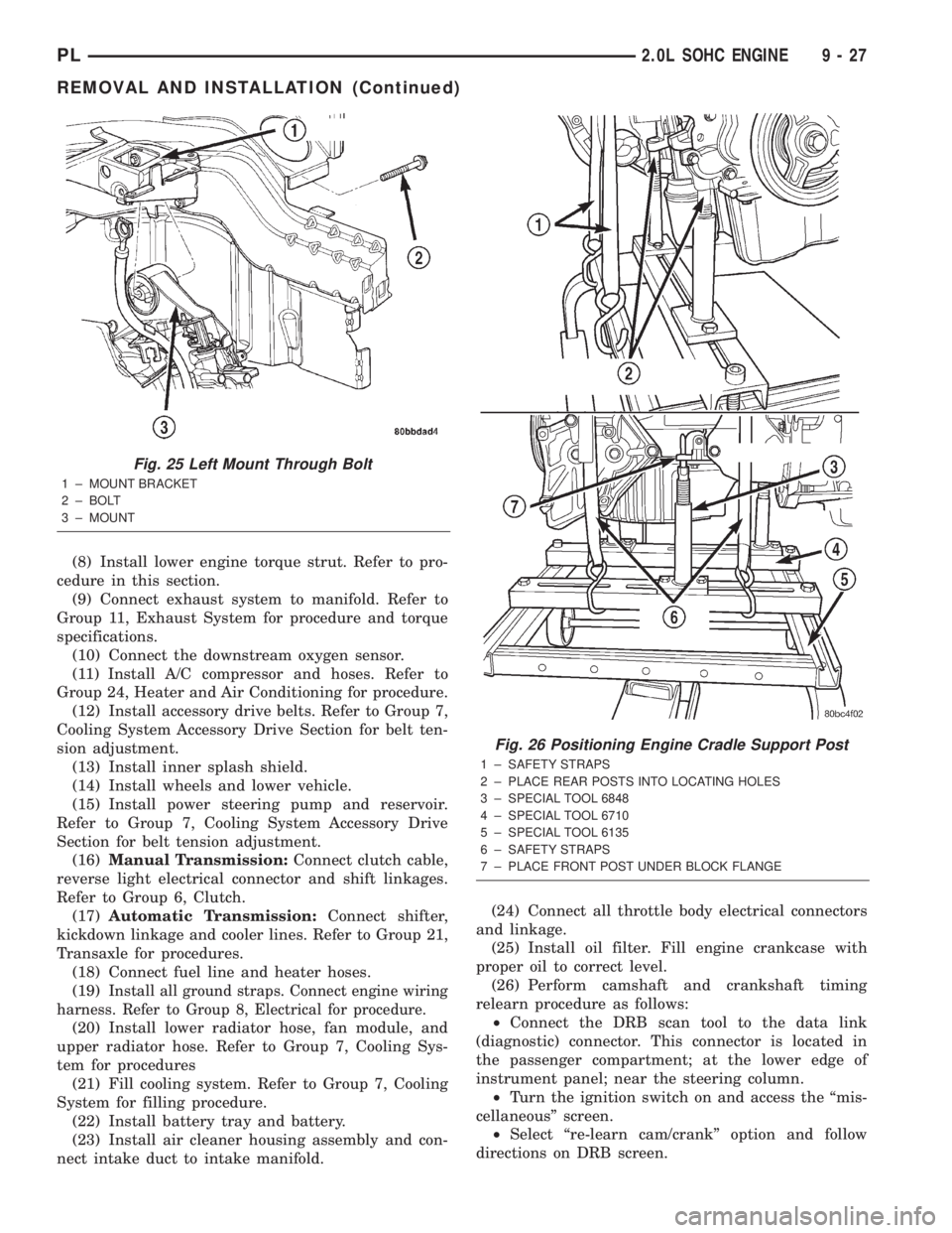
posts (Fig. 26). Tighten mounts to cradle frame. This
will keep support posts from moving when removing
or installing engine and transmission.
(30) Install safety straps around the engine to cra-
dle (Fig. 26). Tighten straps and lock them into posi-
tion.
WARNING: Safety straps MUST be used.(31) Raise vehicle enough to see if straps are tight
enough to hold cradle assembly to engine.
(32) Lower vehicle so weight of the engine and
transmission ONLY is on the cradle assembly.
(33) Remove the upper engine torque strut.
(34) Remove right and left engine and transaxle
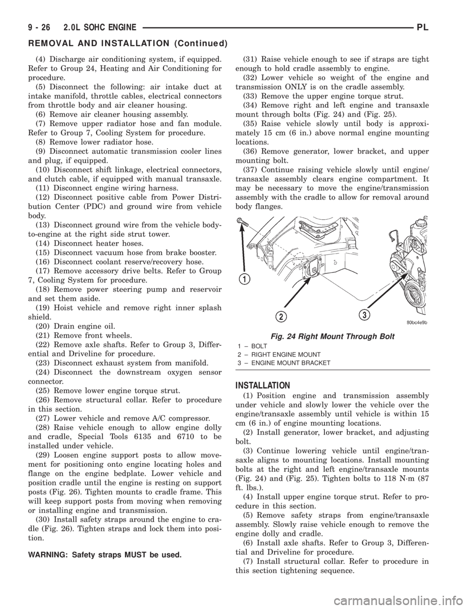
mount through bolts (Fig. 24) and (Fig. 25).
(35) Raise vehicle slowly until body is approxi-
mately 15 cm (6 in.) above normal engine mounting
locations.
(36) Remove generator, lower bracket, and upper
mounting bolt.
(37) Continue raising vehicle slowly until engine/
transaxle assembly clears engine compartment. It
may be necessary to move the engine/transmission
assembly with the cradle to allow for removal around
body flanges.
INSTALLATION
(1) Position engine and transmission assembly
under vehicle and slowly lower the vehicle over the
engine/transaxle assembly until vehicle is within 15
cm (6 in.) of engine mounting locations.
(2) Install generator, lower bracket, and adjusting
bolt.
(3) Continue lowering vehicle until engine/tran-
saxle aligns to mounting locations. Install mounting
bolts at the right and left engine/transaxle mounts
(Fig. 24) and (Fig. 25). Tighten bolts to 118 N´m (87
ft. lbs.).
(4) Install upper engine torque strut. Refer to pro-
cedure in this section.
(5) Remove safety straps from engine/transaxle
assembly. Slowly raise vehicle enough to remove the
engine dolly and cradle.
(6) Install axle shafts. Refer to Group 3, Differen-
tial and Driveline for procedure.
(7) Install structural collar. Refer to procedure in
this section tightening sequence.
Fig. 24 Right Mount Through Bolt
1 ± BOLT
2 ± RIGHT ENGINE MOUNT
3 ± ENGINE MOUNT BRACKET
9 - 26 2.0L SOHC ENGINEPL
REMOVAL AND INSTALLATION (Continued)
Page 750 of 1285
(8) Install lower engine torque strut. Refer to pro-
cedure in this section.
(9) Connect exhaust system to manifold. Refer to
Group 11, Exhaust System for procedure and torque
specifications.
(10) Connect the downstream oxygen sensor.
(11) Install A/C compressor and hoses. Refer to
Group 24, Heater and Air Conditioning for procedure.
(12) Install accessory drive belts. Refer to Group 7,
Cooling System Accessory Drive Section for belt ten-
sion adjustment.
(13) Install inner splash shield.
(14) Install wheels and lower vehicle.
(15) Install power steering pump and reservoir.
Refer to Group 7, Cooling System Accessory Drive
Section for belt tension adjustment.
(16)Manual Transmission:Connect clutch cable,
reverse light electrical connector and shift linkages.
Refer to Group 6, Clutch.
(17)Automatic Transmission:Connect shifter,
kickdown linkage and cooler lines. Refer to Group 21,
Transaxle for procedures.
(18) Connect fuel line and heater hoses.
(19)
Install all ground straps. Connect engine wiring
harness. Refer to Group 8, Electrical for procedure.
(20) Install lower radiator hose, fan module, and
upper radiator hose. Refer to Group 7, Cooling Sys-
tem for procedures
(21) Fill cooling system. Refer to Group 7, Cooling
System for filling procedure.
(22) Install battery tray and battery.
(23) Install air cleaner housing assembly and con-
nect intake duct to intake manifold.(24) Connect all throttle body electrical connectors
and linkage.
(25) Install oil filter. Fill engine crankcase with
proper oil to correct level.
(26) Perform camshaft and crankshaft timing
relearn procedure as follows:
²Connect the DRB scan tool to the data link
(diagnostic) connector. This connector is located in
the passenger compartment; at the lower edge of
instrument panel; near the steering column.
²Turn the ignition switch on and access the ªmis-
cellaneousº screen.
²Select ªre-learn cam/crankº option and follow
directions on DRB screen.
Fig. 25 Left Mount Through Bolt
1 ± MOUNT BRACKET
2 ± BOLT
3 ± MOUNT
Fig. 26 Positioning Engine Cradle Support Post
1 ± SAFETY STRAPS
2 ± PLACE REAR POSTS INTO LOCATING HOLES
3 ± SPECIAL TOOL 6848
4 ± SPECIAL TOOL 6710
5 ± SPECIAL TOOL 6135
6 ± SAFETY STRAPS
7 ± PLACE FRONT POST UNDER BLOCK FLANGE
PL2.0L SOHC ENGINE 9 - 27
REMOVAL AND INSTALLATION (Continued)
Page 751 of 1285
(27) Start engine and run until operating temper-
ature is reached.
(28) Ensure engine is properly positioned. Refer to
Torque Struts in this section for adjustment proce-
dure.
(29) Adjust transmission linkage, if necessary.
INTAKE MANIFOLD
REMOVAL
WARNING: RELEASE FUEL SYSTEM PRESSURE
BEFORE SERVICING FUEL SYSTEM COMPONENTS.
SERVICE VEHICLES IN WELL VENTILATED AREAS
AND AVOID IGNITION SOURCES. NEVER SMOKE
WHILE SERVICING THE VEHICLE.
(1) Disconnect negative cable from battery.
(2) Remove the inlet air duct from intake manifold
to throttle body.
(3) Perform fuel system pressure release procedure
before attempting any repairs.Refer to Group 14,
Fuel System for procedures.
WARNING: WRAP SHOP TOWELS AROUND FUEL
HOSE TO CATCH ANY GASOLINE SPILLAGE
(4) Disconnect fuel supply line quick connect at the
fuel tube assembly. Refer to Group 14, Fuel System
for procedures.
(5) Remove fuel rail assembly attaching screws
and remove fuel rail assembly from engine. Cover
injector holes with suitable covering.
CAUTION: Do not set fuel injectors on their tips,
damage may occur to the injectors
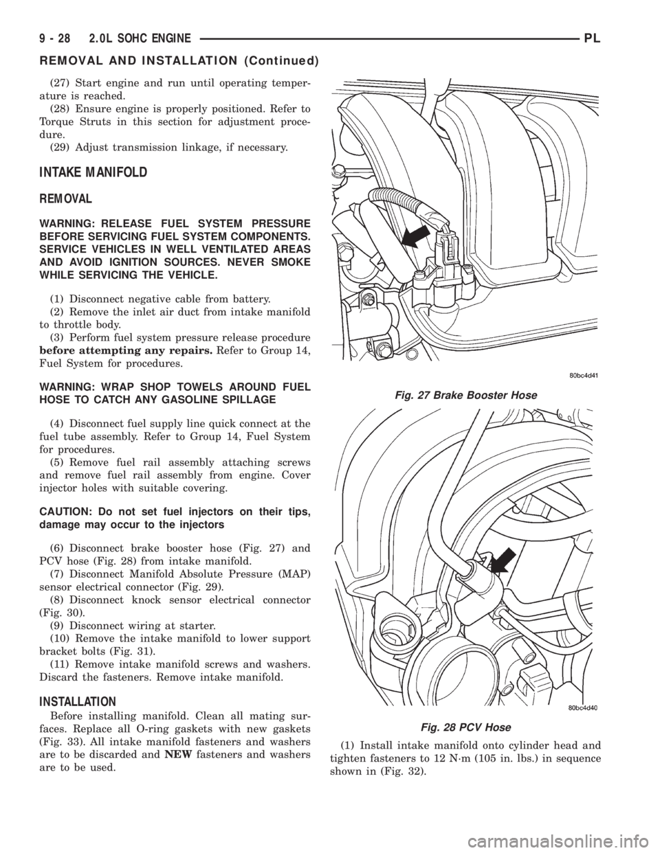
(6) Disconnect brake booster hose (Fig. 27) and
PCV hose (Fig. 28) from intake manifold.
(7) Disconnect Manifold Absolute Pressure (MAP)
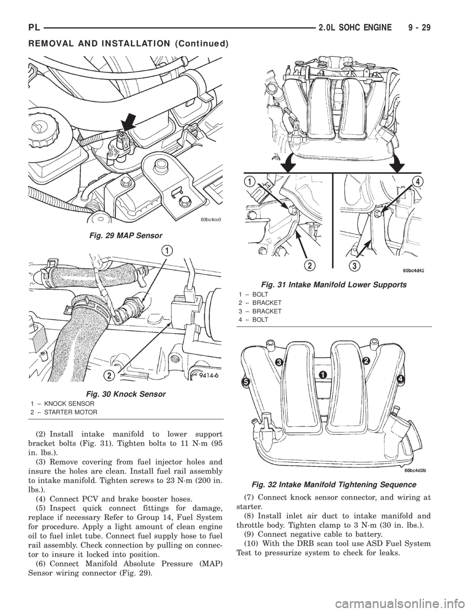
sensor electrical connector (Fig. 29).
(8) Disconnect knock sensor electrical connector
(Fig. 30).
(9) Disconnect wiring at starter.
(10) Remove the intake manifold to lower support
bracket bolts (Fig. 31).
(11) Remove intake manifold screws and washers.
Discard the fasteners. Remove intake manifold.
INSTALLATION
Before installing manifold. Clean all mating sur-
faces. Replace all O-ring gaskets with new gaskets
(Fig. 33). All intake manifold fasteners and washers
are to be discarded andNEWfasteners and washers
are to be used.(1) Install intake manifold onto cylinder head and
tighten fasteners to 12 N´m (105 in. lbs.) in sequence
shown in (Fig. 32).
Fig. 27 Brake Booster Hose
Fig. 28 PCV Hose
9 - 28 2.0L SOHC ENGINEPL
REMOVAL AND INSTALLATION (Continued)
Page 752 of 1285
(2) Install intake manifold to lower support
bracket bolts (Fig. 31). Tighten bolts to 11 N´m (95
in. lbs.).
(3) Remove covering from fuel injector holes and
insure the holes are clean. Install fuel rail assembly
to intake manifold. Tighten screws to 23 N´m (200 in.
lbs.).
(4) Connect PCV and brake booster hoses.
(5) Inspect quick connect fittings for damage,
replace if necessary Refer to Group 14, Fuel System
for procedure. Apply a light amount of clean engine
oil to fuel inlet tube. Connect fuel supply hose to fuel
rail assembly. Check connection by pulling on connec-
tor to insure it locked into position.
(6) Connect Manifold Absolute Pressure (MAP)
Sensor wiring connector (Fig. 29).(7) Connect knock sensor connector, and wiring at
starter.
(8) Install inlet air duct to intake manifold and
throttle body. Tighten clamp to 3 N´m (30 in. lbs.).
(9) Connect negative cable to battery.
(10) With the DRB scan tool use ASD Fuel System
Test to pressurize system to check for leaks.
Fig. 29 MAP Sensor
Fig. 30 Knock Sensor
1 ± KNOCK SENSOR
2 ± STARTER MOTOR
Fig. 31 Intake Manifold Lower Supports
1 ± BOLT
2 ± BRACKET
3 ± BRACKET
4 ± BOLT
Fig. 32 Intake Manifold Tightening Sequence
PL2.0L SOHC ENGINE 9 - 29
REMOVAL AND INSTALLATION (Continued)
Page 753 of 1285
CAUTION: When using the ASD Fuel System Test,
the Auto Shutdown (ASD) relay will remain ener-
gized for 7 minutes or until the ignition switch is
turned to the OFF position, or Stop All Test is
selected.
EXHAUST MANIFOLD
REMOVAL
(1) Disconnect negative cable from battery.
(2) Raise vehicle on hoist.
(3) Remove bolt attaching the wire harness heat
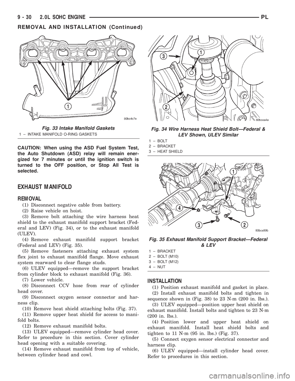
shield to the exhaust manifold support bracket (Fed-
eral and LEV) (Fig. 34), or to the exhaust manifold
(ULEV).
(4) Remove exhaust manifold support bracket
(Federal and LEV) (Fig. 35).
(5) Remove fasteners attaching exhaust system
flex joint to exhaust manifold flange. Move exhaust
system rearward to clear flange studs.
(6) ULEV equippedÐremove the support bracket
from cylinder block to exhaust manifold (Fig. 36).
(7) Lower vehicle.
(8) Disconnect CCV hose from rear of cylinder
head cover.
(9) Disconnect oxygen sensor connector and har-
ness clip.
(10) Remove heat shield attaching bolts (Fig. 37).
(11) Remove upper heat shield for access to mani-
fold bolts.
(12) Remove exhaust manifold bolts.
(13) ULEV equippedÐremove cylinder head cover.
Refer to procedure in this section. Cover cylinder
head opening with a suitable covering.
(14) Remove exhaust manifold from top of vehicle,
between cylinder head and cowl.
INSTALLATION
(1) Position exhaust manifold and gasket in place.
(2) Install exhaust manifold bolts and tighten in
sequence shown in (Fig. 38) to 23 N´m (200 in. lbs.).
(3) ULEV equippedÐposition upper heat shield on
exhaust manifold. Install bolts and tighten to 23 N´m
(200 in. lbs.).
(4) Position lower and upper heat shield on
exhaust manifold. Install heat shield bolts and
tighten to 11 N´m (95 in. lbs.) (Fig. 37).
(5) Connect oxygen sensor electrical connector and
harness clip.
(6) ULEV equippedÐinstall cylinder head cover.
Refer to procedures in this section.
Fig. 33 Intake Manifold Gaskets
1 ± INTAKE MANIFOLD O-RING GASKETS
Fig. 34 Wire Harness Heat Shield BoltÐFederal &
LEV Shown, ULEV Similar
1 ± BOLT
2 ± BRACKET
3 ± HEAT SHIELD
Fig. 35 Exhaust Manifold Support BracketÐFederal
& LEV
1 ± BRACKET
2 ± BOLT (M10)
3 ± BOLT (M12)
4 ± NUT
9 - 30 2.0L SOHC ENGINEPL
REMOVAL AND INSTALLATION (Continued)
Page 756 of 1285
NOTE: Position seal with the concave side facing
the installation tool.
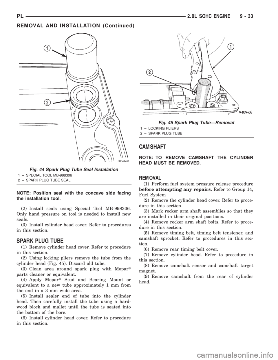
(2) Install seals using Special Tool MB-998306.
Only hand pressure on tool is needed to install new
seals.
(3) Install cylinder head cover. Refer to procedures
in this section.
SPARK PLUG TUBE
(1) Remove cylinder head cover. Refer to procedure
in this section.
(2) Using locking pliers remove the tube from the
cylinder head (Fig. 45). Discard old tube.
(3) Clean area around spark plug with Mopart
parts cleaner or equivalent.
(4) Apply MopartStud and Bearing Mount or
equivalent to a new tube approximately 1 mm from
theendina3mmwide area.
(5) Install sealer end of tube into the cylinder
head. Then carefully install the tube using a hard-
wood block and mallet until the tube is seated into
the bottom of the bore.
(6) Install cylinder head cover. Refer to procedure
in this section.
CAMSHAFT
NOTE: TO REMOVE CAMSHAFT THE CYLINDER
HEAD MUST BE REMOVED.
REMOVAL
(1) Perform fuel system pressure release procedure
before attempting any repairs.Refer to Group 14,
Fuel System
(2) Remove the cylinder head cover. Refer to proce-
dure in this section.
(3) Mark rocker arm shaft assemblies so that they
are installed in their original positions.
(4) Remove rocker arm shaft bolts. Refer to proce-
dure in this section.
(5) Remove timing belt, timing belt tensioner, and
camshaft sprocket. Refer to procedures in this sec-
tion.
(6) Remove rear timing belt cover.
(7) Remove cylinder head. Refer to procedure in
this section.
(8) Remove camshaft sensor and camshaft target
magnet.
(9) Remove camshaft from the rear of cylinder
head.
Fig. 44 Spark Plug Tube Seal Installation
1 ± SPECIAL TOOL MB-998306
2 ± SPARK PLUG TUBE SEAL
Fig. 45 Spark Plug TubeÐRemoval
1 ± LOCKING PLIERS
2 ± SPARK PLUG TUBE
PL2.0L SOHC ENGINE 9 - 33
REMOVAL AND INSTALLATION (Continued)