Page 1614 of 4592
DI02Y±02
D00938
Shift Solenoid Valve SLVehicle Speed SensorECMO/D Main SwitchO/D OFF Indicator Light
DLC3
Stop Light Switch
Shift Solenoid Valve No.2
Shift Solenoid Valve No.1 Park/Neutral Position Switch
DI±402
± DIAGNOSTICSAUTOMATIC TRANSAXLE (A140E)
637 Author�: Date�:
PARTS LOCATION
Page 1617 of 4592

DI±405
640 Author�: Date�:
PROBLEM SYMPTOMS TABLE
If a normal code is displayed during the DTC check but the trouble still occurs, check the circui")
DI030±02
± DIAGNOSTICSAUTOMATIC TRANSAXLE (A140E)
DI±405
640 Author�: Date�:
PROBLEM SYMPTOMS TABLE
If a normal code is displayed during the DTC check but the trouble still occurs, check the circuits for each
symptom in the order given in the charts on the following pages and proceed to the page given for trouble-
shooting.
The Matrix Chart is divided into 3 chapters.
Chapter 1: Electronic Circuit Matrix Chart
Chapter 2: On±vehicle Repair Matrix Chart
Chapter 3: Off±vehicle repair Matrix Chart
�If the instruction ºProceed to next circuit inspection shown on matrix chartº is given in the flow
chart for each circuit, proceed to the circuit with the next highest number in the table to continue
the check.
�If the trouble still occurs even though there are no abnormalities in any of the other circuits, then
check and replace the ECM.
1. Chapter 1: Electronic Circuit Matrix Chart
SymptomSuspect AreaSee page
No up±shift
(A particular gear, from 1st to 3rd gear, is not up±shifted)1. ECMIN±31
No up±shift (3rd " O/D)
1. O/D main switch & O/D OFF indicator light circuit
2. O/D cancel signal circuit
3. ECMDI±431
DI±428
IN±31
No down±shift (O/D " 3rd)1. ECMIN±31
No down±shift
(A particular gear, from 3rd to 1st gear, is not down±shifted)1. ECMIN±31
No lock±up or No lock±up off1. Stop light switch circuit
2. ECMDI±423
IN±31
Shift point too high or too low1. ECMIN±31
Up±shift to O/D from 3rd while O/D main switch is OFF1. O/D main switch & O/D OFF indicator light circuit
2. ECMDI±431
IN±31
Up±shift to O/D from 3rd while engine is cold1. ECMIN±31
Poor acceleration1. ECMIN±31
No kick±down1. ECMIN±31
Engine stalls when starting off or stopping1. ECMIN±31
Page 1625 of 4592

Position
NORMALSHIFT SOLENOID NO.1
MALFUNCTIONING
Solenoid valveNo.1 No.2GearSHIFT SOLENOID NO.2
MALFUNCTIONINGBOTH SOLENOIDS MAL-
FUNCTIONINGSolenoid valve
No.1 No.2GearSolenoid valve
No.1 No.2GearGear when shift selector is
manually operated
D
2
LON
ONOFF
ON
ON OFF
OFF OFF
ON
ONOFF
ON
ON OFF
ON
ON ONOFF1st
2nd
3rd
O/D
1st
2nd
3rd
1st
2ndX
X
X
X
X
X
X
X
XON
ON
OFF
OFFON
ON
ON3rd 3rd
O/D
3rd
3rd
1st
2ndX
X
X
X
X
X
X
X
X ON
ON OFF OFF
OFF
ON
ON1st
1st O/D O/D
3rd
1st
1stO/D O/D O/D
O/D
3rd 3rd
3rd
1st
1st
X: MalfunctionsON
ON3rd
3rdO/D
3rd
OFF OFF
± DIAGNOSTICSAUTOMATIC TRANSAXLE (A140E)
DI±413
648 Author�: Date�:
DTC P0753, P0758 Shift Solenoid A/B Electrical Malfunc-
tion (Shift Solenoid Valve No.1/No.2)
CIRCUIT DESCRIPTION
Shifting from 1st to O/D is performed in combination with ON and OFF of the shift solenoid valves No.1 and
No.2 controlled by ECM. If an open or short circuit occurs in either of the shift solenoid valves, the ECM con-
trols the remaining normal shift solenoid valve to allow the vehicle to be operated smoothly (Fail safe func-
tion).
Fail Safe Function:
If either of the shift solenoid valve circuits develops an open or short, the ECM turns the other shift solenoid
ON and OFF to shift to the gear positions shown in the table below. The ECM also turns the shift solenoid
valve SL OFF at the same time. If both solenoids are malfunction, hydraulic control cannot be performed
electronically and must be done manually.
Manual shifting as shown in the following table must be done (In the case of a short circuit, the ECM stops
sending current to the short circuited solenoid).
Check the shift solenoid valve No.1 when DTC P0753 is output and check the shift solenoid valve No.2 when
DTC P0758 is output.
DTC No.DTC Detecting ConditionTrouble Area
P0753
P0758
The ECM checks for an open or short circuit in the shift sole-
noid valves No.1 and No.2 circuit when it changes gear posi-
tion.
The ECM records DTC P0753 or P0758 if condition (a) or (b) is
detected once, but it does not light up MIL.
After 1 sec. ECM detects condition (a) or (b) in a trip again, it
causes the MIL to light up.
(a) When the solenoid is energized, the solenoid resistance is
8 W or less and is counted.
(b) When the solenoid is not energized, the solenoid resistance
is 100 kW or more and is counted.
�Open or short in shift solenoid valve No.1/No.2 circuit
�Shift solenoid valve No.1/No.2
�ECM
DI033±02
Page 1635 of 4592
± DIAGNOSTICSAUTOMATIC TRANSAXLE (A140E)
DI±423
658 Author�: Date�:
DTC P1520 Stop Light Switch Signal Malfunction
CIRCUIT DESCRIPTION
The purpose of this circuit is to prevent the engine from stalling, while driving in lock±up condition, when
brakes are suddenly applied.
When the brake pedal is depressed, this switch sends a signal to ECM. Then the ECM cancels operation
of the lock±up clutch while braking is in progress.
DTC No.DTC Detecting ConditionTrouble Area
P1520No stop light switch signal to ECM during driving.
(2 trip detection logic)�Open or short in stop light switch circuit
�Stop light switch
�ECM
WIRING DIAGRAM
See page DI±170.
INSPECTION PROCEDURE
See page DI±170.
DI036±02
Page 1638 of 4592
(+) (+)
(±)
Position
P, N
R
D
2
LNSW±Body
groundR±Body
ground2±Body
groundL±Body
grou")
D00043 Q08479BE3840D00994
w/ Engine Immobiliser System
w/o Engine Immobiliser SystemON
NSW
LL
2
R
NSWR
2
(±)(+) (+)
(±)
Position
P, N
R
D
2
LNSW±Body
groundR±Body
ground2±Body
groundL±Body
ground
0 V
0 V0 V0 V
0 V
0 V
0 V 0 V
0 V
0 V 0 V
0 V
0 V 9 ~ 14 V*
9 ~ 14 V
9 ~ 14 V
9 ~ 14 V9 ~ 14 V
9 ~ 14 V 9 ~ 14 V*
DI±426
± DIAGNOSTICSAUTOMATIC TRANSAXLE (A140E)
661 Author�: Date�:
INSPECTION PROCEDURE
1 Read PNP, REVERSE, 2ND and LOW signals.
When using TOYOTA hand±held tester:
PREPARATION:
(a) Remove the DLC3 cover.
(b) Connect a TOYOTA hand±held tester to the DLC3.
(c) Turn the ignition switch ON and TOYOTA hand±held tes-
ter main switch ON.
CHECK:
Shift the shift lever into the P, R, N, 2 and L positions, and read
the PNP, REVERSE, 2ND and LOW signals on the TOYOTA
hand±held tester.
OK:
Shift positionSignal
22ND OFF " ON
LLOW OFF " ON
RREVERSE OFF " ON
P, NPNP OFF " ON
When not using TOYOTA hand±held tester:
PREPARATION:
Turn the ignition switch ON.
CHECK:
Measure voltage between terminals NSW, 2, L and R of ECM
and body ground when the shift lever is shifted in the following
positions.
OK:
HINT:
The voltage will drop slightly due to lighting up of the back up
light.
OK Proceed to next circuit inspection shown on
matrix chart (See page DI±405).
NG
Page 1643 of 4592

D01810
: w/ Engine Immobiliser System
: w/o Engine Immobiliser System
: O/D Main Switch
Contacts go open with switch pushed in
Contacts go closed with switch pushed once againInstrument
Panel J/BIgnition Switch
1B1
AM1
W
I16
7 1
22
1K2
AM1 IG1
B ± Y
O/D OFF
Indicator Light
(Combination Meter) R ± L
R ± LGAUGE
J4
Junction
Connector
DI164
2
1D 1K
D12
C8G ± OC
C8
W ± B C
CG ± O
G ± OJ6
Junction
ConnectorECM
5
*1B+
E77*2
E7OD2G ± O
IG311
O2 2
(*3)
O/D Main
Switch
O2
4
W ± B A
IF AJ5
Junction
Connector B ± R
1
FUSIBLE
LINK
BLOCKALT F9B ± R
2
F9
1
F4B ± GFL
MAIN
Battery
*3 *2 *1
1 Instrument
Panel J/B
± DIAGNOSTICSAUTOMATIC TRANSAXLE (A140E)
DI±431
666 Author�: Date�:
O/D Main Switch & O/D OFF Indictor Light Circuit
CIRCUIT DESCRIPTION
The O/D main switch contacts go open when the switch is pushed in and go closed when it is pushed out.
In O/D main switch in OFF position, the O/D OFF indicator light lights up, and the ECM prohibits shifting over-
drive.
WIRING DIAGRAM
DI1J1±01
Page 1644 of 4592
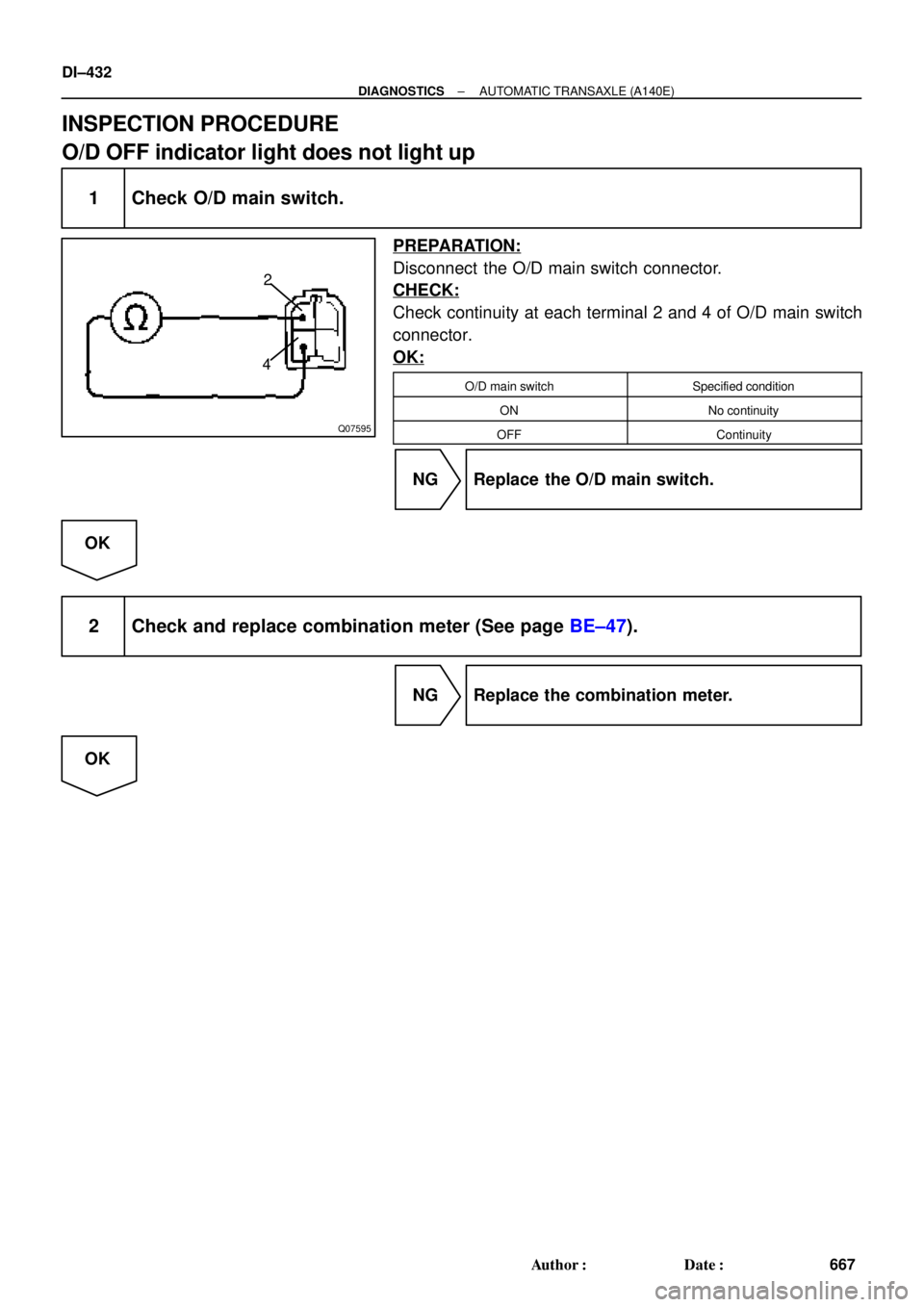
Q07595
2
4
DI±432
± DIAGNOSTICSAUTOMATIC TRANSAXLE (A140E)
667 Author�: Date�:
INSPECTION PROCEDURE
O/D OFF indicator light does not light up
1 Check O/D main switch.
PREPARATION:
Disconnect the O/D main switch connector.
CHECK:
Check continuity at each terminal 2 and 4 of O/D main switch
connector.
OK:
O/D main switchSpecified condition
ONNo continuity
OFFContinuity
NG Replace the O/D main switch.
OK
2 Check and replace combination meter (See page BE±47).
NG Replace the combination meter.
OK
Page 1646 of 4592
DI±434
± DIAGNOSTICSAUTOMATIC TRANSAXLE (A140E)
669 Author�: Date�:
4 Check harness and connector between O/D OFF indicator light and ECM
(See page IN±31).
NG Repair or replace the harness or connector.
OK
Check and replace the ECM
(See page IN±31).