Page 1662 of 4592
DI02G±02
Q07932
Engine Coolant Temp. SensorCruise Control ECUThrottle Position Sensor
O/D Main Switch
O/D OFF Indicator LIght
DLC3
DLC2
Stop Light Switch
Vehicle Speed Sensor
Shift Solenoid Valve SLN
Shift Solenoid Valve No.1, No2 Shift Solenoid Valve SL
Park/Neutral Position Switch Direct Clutch Speed SensorECM
Crankshaft Position
Sensor
DI±450
± DIAGNOSTICSAUTOMATIC TRANSAXLE (A541E)
685 Author�: Date�:
PARTS LOCATION
Page 1674 of 4592

Position
NORMALSHIFT SOLENOID NO.1
MALFUNCTIONING
Solenoid valveNo.1 No.2GearSHIFT SOLENOID NO.2
MALFUNCTIONINGBOTH SOLENOIDS MAL-
FUNCTIONINGSolenoid valve
No.1 No.2GearSolenoid valve
No.1 No.2GearGear when shift selector is
manually operated
D
2
LON
ONOFF
ON
ON OFF
OFF OFF
ON
ONOFF
ON
ON OFF
ON
ON ONOFF1st
2nd
3rd
O/D
1st
2nd
3rd
1st
2ndX
X
X
X
X
X
X
X
XON
ON
OFF
OFFON
ON
ON3rd 3rd
O/D
3rd
3rd
1st
2ndX
X
X
X
X
X
X
X
X OFF
OFFON
ON OFF OFF
OFF
ON
ON1st
O/D
O/D1st O/D O/D
O/D
1st
1stO/D O/D O/D
O/D
O/D O/D
O/D
1st
1st
X: MalfunctionsON
ON3rd
3rd
DI±462
± DIAGNOSTICSAUTOMATIC TRANSAXLE (A541E)
697 Author�: Date�:
DTC P0753, P0758 Shift Solenoid A/B Electrical Malfunc-
tion (Shift Solenoid Valve No.1/No.2)
CIRCUIT DESCRIPTION
Shifting from 1st to O/D is performed in combination with ON and OFF of the shift solenoid valves No.1 and
No.2 controlled by ECM. If an open or short circuit occurs in either of the shift solenoid valves, the ECM con-
trols the remaining normal shift solenoid valve to allow the vehicle to be operated smoothly (Fail safe func-
tion).
Fail Safe Function:
If either of the shift solenoid valve circuits develops an open or short, the ECM turns the other shift solenoid
ON and OFF to shift to the gear positions shown in the table below. The ECM also turns the shift solenoid
valve SL OFF at the same time. If both solenoids are malfunction, hydraulic control cannot be performed
electronically and must be done manually.
Manual shifting as shown in the following table must be done (In the case of a short circuit, the ECM stops
sending current to the short circuited solenoid).
Check the shift solenoid valve No.1 when DTC P0753 is output and check the shift solenoid valve No.2 when
DTC P0758 is output.
DTC No.DTC Detecting ConditionTrouble Area
P0753
P0758
The ECM checks for an open or short circuit in the shift sole-
noid valves No.1 and No.2 circuit when it changes.
The ECM records DTC P0753 or P0758 if condition (a) or (b) is
detected once, but it does not light up MIL.
After ECM detects condition (a) or (b) continuously 8 times or
more in a trip and the MIL light up.
(a) When the solenoid is energized, the solenoid resistance
is 8 W or less and is counted.
(b) When the solenoid is not energized, the solenoid resistance
is 100 kW or more and is counted.
�Open or short in shift solenoid valve No.1/No.2 circuit
�Shift solenoid valve No.1/No.2
�ECM
DI02L±02
Page 1684 of 4592
DI±472
± DIAGNOSTICSAUTOMATIC TRANSAXLE (A541E)
707 Author�: Date�:
DTC P1520 Stop Light Switch Signal Malfunction
CIRCUIT DESCRIPTION
The purpose of this circuit is to prevent the engine from stalling, while driving in lock±up condition, when
brakes are suddenly applied.
When the brake pedal is operated, this switch sends a signals to ECM. Then the ECM cancels operation
of the lock±up clutch while braking is in progress.
DTC No.DTC Detecting ConditionTrouble Area
P1520No stop light switch signal to ECM during driving.
(2 trip detection logic)�Open or short in stop light switch circuit
�Stop light switch
�ECM
WIRING DIAGRAM
See page DI±363.
INSPECTION PROCEDURE
See page DI±363.
DI02O±02
Page 1694 of 4592

BE3840D00052D00836D01914
Except California, w/ Engine Immobilizer
and / or TRAC:
California, w/ Engine Immobilizer
and / or TRAC:ON
L
NSW
2
R
2R
L
NSW
Position
P, N
R
D
2
LNSW±Body
groundR±Body
ground2±Body
groundL±Body
ground
0 V
0 V0 V0 V
0 V
0 V
0 V 0 V
0 V
0 V 0 V
0 V
0 V 9 ~ 14 V*
9 ~ 14 V
9 ~ 14 V
9 ~ 14 V9 ~ 14 V
9 ~ 14 V 9 ~ 14 V* DI±482
± DIAGNOSTICSAUTOMATIC TRANSAXLE (A541E)
717 Author�: Date�:
INSPECTION PROCEDURE
1 Read PNP, REVERSE, 2ND and LOW signals.
When using TOYOTA hand±held tester.
PREPARATION:
(a) Remove the DLC3 cover.
(b) Connect a TOYOTA hand±held tester to the DLC3.
(c) Turn the ignition switch ON and TOYOTA hand±held tes-
ter main switch ON.
CHECK:
Shift lever into the P, R, N, 2 and L positions, and read the PNP,
REVERSE, 2ND and LOW signals on the TOYOTA hand±held
tester.
OK:
Shift positionSignal
22ND OFF " ON
LLOW OFF " ON
RREVERSE OFF " ON
P, NNSW OFF " ON
When not using TOYOTA hand±held tester.
PREPARATION:
Turn the ignition switch ON.
CHECK:
Measure voltage between terminals NSW, 2, L and R of ECM
and body ground when the shift lever is shifted to the following
positions.
OK:
HINT:
*: The voltage will drop slightly due to lighting up of the back up
light.
Page 1699 of 4592
D01900
ECM
4E7OD2B+
G±O
IG1 C
CC
O2 O/D Main
Switch O/D Indicator
Light
C8 712
R±L
D
Ignition Switch
11K2
1DGAUGE J/C J4
G±OG±O
IG3
J/C J6
G±O
O2
B±Y
AM11B 1K
C10
AM1
F9 D
R±L
I16 W 21
24
I16 2
12
B±R
B±R
B±R1
2
F9Fusible Link Block
FL Main
Battery 1
F4B±GW±B
A
J/C J5
IF A
W±B
Left Kick Panel
*1: Except California, w/ Engine Immobilizer and / or TRAC
*2: California, w/ Engine Immobilizer and / or TRACInstrument Panel J/B
Instrument Panel J/B11106 *2*1
ALTE8
± DIAGNOSTICSAUTOMATIC TRANSAXLE (A541E)
DI±487
722 Author�: Date�:
O/D Main Switch & O/D OFF Indictor Light Circuit
CIRCUIT DESCRIPTION
The O/D main switch contacts go open when the switch is pushed in and go closed when it is pushed out.
In O/D main switch at OFF position, the O/D OFF indicator light lights up, and the ECM prohibits shifting over-
drive.
WIRING DIAGRAM
DI1KD±01
Page 1700 of 4592
Q07595
2
4
DI±488
± DIAGNOSTICSAUTOMATIC TRANSAXLE (A541E)
723 Author�: Date�:
INSPECTION PROCEDURE
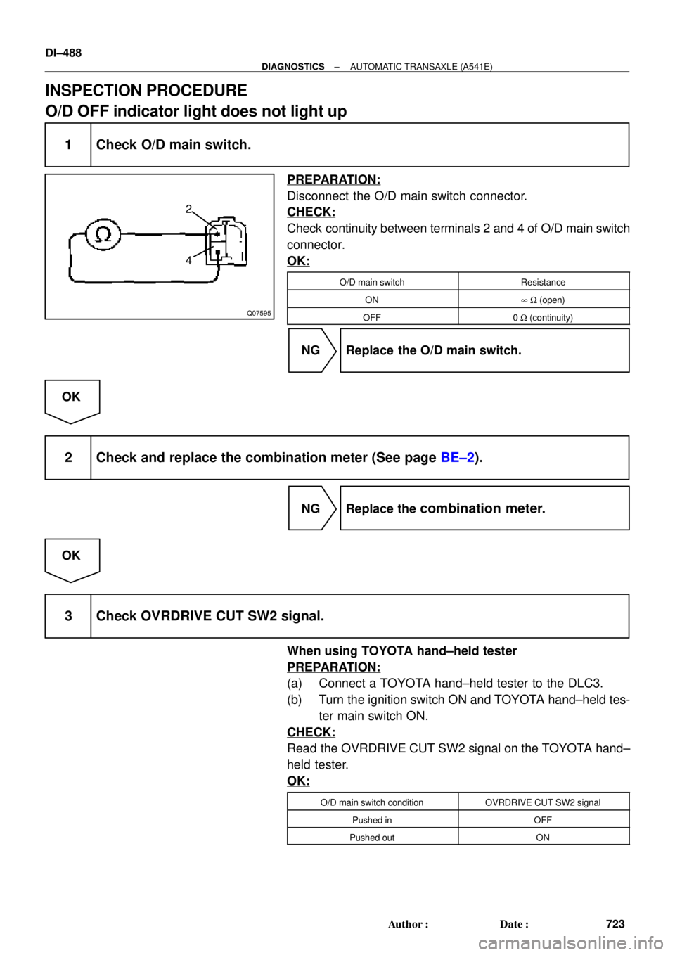
O/D OFF indicator light does not light up
1 Check O/D main switch.
PREPARATION:
Disconnect the O/D main switch connector.
CHECK:
Check continuity between terminals 2 and 4 of O/D main switch
connector.
OK:
O/D main switchResistance
ON8 W (open)
OFF0 W (continuity)
NG Replace the O/D main switch.
OK
2 Check and replace the combination meter (See page BE±2).
NG Replace the combination meter.
OK
3 Check OVRDRIVE CUT SW2 signal.
When using TOYOTA hand±held tester
PREPARATION:
(a) Connect a TOYOTA hand±held tester to the DLC3.
(b) Turn the ignition switch ON and TOYOTA hand±held tes-
ter main switch ON.
CHECK:
Read the OVRDRIVE CUT SW2 signal on the TOYOTA hand±
held tester.
OK:
O/D main switch conditionOVRDRIVE CUT SW2 signal
Pushed inOFF
Pushed outON
Page 1701 of 4592
BE3840
D00837Q07662D01916
Except California, w/ Engine Immobilizer
and / or TRAC:
California, w/ Engine Immobilizer
and / or TRAC:
OD2 OD2
(+) (±) ON
(+) (±)
± DIAGNOSTICSAUTOMATIC TRANSAXLE (A541E)
DI±489
724 Author�: Date�:
When not using TOYOTA hand±held tester
PREPARATION:
Turn the ignition switch ON.
CHECK:
Check voltage between terminal OD2 of ECM and body ground.
OK:
O/D main switchVoltage
OFFBelow 1 V
ON10 ~ 14 V
NG Check and replace the ECM.
NG
4 Check harness and connector between O/D OFF indicator light and ECM
(See page IN±31).
NG Repair or replace the harness or connector.
OK
Check and replace the ECM.
Page 1702 of 4592
Q07595
2
4
DI±490
± DIAGNOSTICSAUTOMATIC TRANSAXLE (A541E)
725 Author�: Date�:
O/D OFF indicator light remains on
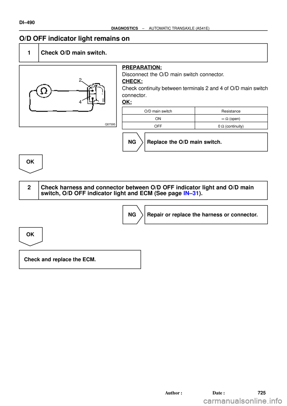
1 Check O/D main switch.
PREPARATION:
Disconnect the O/D main switch connector.
CHECK:
Check continuity between terminals 2 and 4 of O/D main switch
connector.
OK:
O/D main switchResistance
ON8 W (open)
OFF0 W (continuity)
NG Replace the O/D main switch.
OK
2 Check harness and connector between O/D OFF indicator light and O/D main
switch, O/D OFF indicator light and ECM (See page IN±31).
NG Repair or replace the harness or connector.
OK
Check and replace the ECM.


 (±) ON
(+) (±)
± DIAGNOSTICSAUTOMATIC TRANSAXLE (A541")