Page 1735 of 4592

F00124
Battery MAIN B±GF4 F91
ALT FL Block
B±R STOP Instrument Panel J/B
1C1B4
7Stop Light
Switch
2G±W
1R 1S5J27 J28J/C
Light Failure
Sensor
J/C
J40
BL
BP W±BG±W
A195
STPABS ECU
R
G±R
High
Mounted
Stop
LightRight
Stop
LightLeft
Stop
Light
A 1Instrument
Panel J/B
G±R W
11R
2 4
G±W
G±R
W±B
W±B
W±B AAC
W±B W±BH10 R11
R9
H10R9
R11 2
122
5 5 G±W
1
2 7
Under the
Left Center
PillarBack Panel
Center
± DIAGNOSTICSANTI±LOCK BRAKE SYSTEM (DENSO Made)
DI±523
758 Author�: Date�:
DTC 49 Stop Light Switch Circuit
CIRCUIT DESCRIPTION
DTC No.DTC Detecting ConditionTrouble Area
49
ABS ECU terminal IG1 voltage is 9.5 V to 18.5 V and ABS
is in non±operation, the open circuit of the stop light switch
circuit continues for 0.3 sec. or more.�Stop light switch
�Stop light switch circuit
WIRING DIAGRAM
INSPECTION PROCEDURE
1 Check operation of stop light.
CHECK:
Check that stop light lights up when brake pedal is depressed and turns off when brake pedal is released.
NG Repair stop light circuit (See page BE±37).
OK
DI03N±03
Page 1736 of 4592
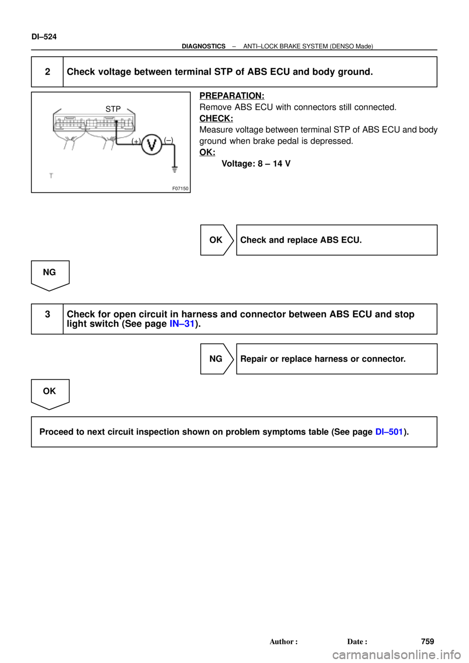
F07150
(+)(±) STP
DI±524
± DIAGNOSTICSANTI±LOCK BRAKE SYSTEM (DENSO Made)
759 Author�: Date�:
2 Check voltage between terminal STP of ABS ECU and body ground.
PREPARATION:
Remove ABS ECU with connectors still connected.
CHECK:
Measure voltage between terminal STP of ABS ECU and body
ground when brake pedal is depressed.
OK:
Voltage: 8 ± 14 V
OK Check and replace ABS ECU.
NG
3 Check for open circuit in harness and connector between ABS ECU and stop
light switch (See page IN±31).
NG Repair or replace harness or connector.
OK
Proceed to next circuit inspection shown on problem symptoms table (See page DI±501).
Page 1739 of 4592
± DIAGNOSTICSANTI±LOCK BRAKE SYSTEM (DENSO Made)
DI±527
762 Author�: Date�:
DTC Always ON ABS ECU Malfunction
CIRCUIT DESCRIPTION
DTC No.DTC Detecting ConditionTrouble Area
Always ONABS ECU internal malfunction is detected.�ECU
�Battery
Fail safe function:
If trouble occurs in the power source circuit, the ECU cuts off current to the ABS solenoid relay and prohibits
ABS control.
INSPECTION PROCEDURE
1 Is DTC output?
Check DTC on page DI±493.
YES Repair circuit indicated by the code output.
NO
2 Is normal code displayed?
YES Check ABS solenoid relay. Check for short cir-
cuit in harness and connector between ABS so-
lenoid relay and DLC1 (See page IN±31).
NO
3 Is ABS warning light go off?
YES Check for open or short circuit in harness and
connector between ECU±IG fuse and ABS ECU
(See page IN±31).
NO
DI03P±04
Page 1740 of 4592
DI±528
± DIAGNOSTICSANTI±LOCK BRAKE SYSTEM (DENSO Made)
763 Author�: Date�:
4 Check battery positive voltage.
CHECK:
Check the battery positive voltage.
OK:
10 ± 14 V
NG Check and repair the charging system
5S±FE engine: (See page CH±1)
1MZ±FE engine: (See page CH±1).
OK
5 Check ABS warning light.
PREPARATION:
(a) Disconnect the connector from the ABS ECU.
(b) Turn the ignition switch ON.
CHECK:
Check the ABS warning light goes off.
OK Check and replace ABS ECU.
NG
Check for short circuit in harness and connector between ABS warning light, DLC1, DLC2, and
ABS ECU (See page IN±31).
Page 1741 of 4592

F07217
Engine Room R/B No. 3
ABS Solenoid Relay
3
ABS
Actuator
A4 1
2
5 BatteryGAUGE Instrument Panel J/B
J/C
J4
D
ABS ECU 33 3 3
EA34 6
ABS ECUD
IK28
R±L
II3 4
DLC1 R±L
G±B
II3 5 Short
Pin
W±B
ABS ECU W±L
G±B
C
CC R±L
R±L 1D2
7
4
R±L
A19WA IG3 12
11 G±B 4
G±B C10
C10
J/C
J29ABS Warning
Light
23
22 R±L
± DIAGNOSTICSANTI±LOCK BRAKE SYSTEM (DENSO Made)
DI±529
764 Author�: Date�:
ABS Warning Light Circuit
CIRCUIT DESCRIPTION
If the ECU detects trouble, it lights the ABS warning light while at the same time prohibiting ABS control. At
this time, the ECU records a DTC in memory.
After removing the short pin of the DLC1, connect terminals Tc and E
1 of the DLC1 or DLC2 to make the
ABS warning light blink and output the DTC.
WIRING DIAGRAM
INSPECTION PROCEDURE
Troubleshooting in accordance with the chart below for each trouble symptom.
ABS warning light does not light upGo to step 1
ABS warning light remains onGo to step 3
1 Check ABS warning light.
See combination meter troubleshooting on page BE±2.
NG Repair bulb or combination meter assembly.
OK
DI03Q±03
Page 1743 of 4592
± DIAGNOSTICSANTI±LOCK BRAKE SYSTEM (DENSO Made)
DI±531
766 Author�: Date�:
3 Is DTC output?
Check DTC on page DI±493.
YES Repair circuit indicated by the code output.
NO
4 Does ABS warning light go off if short pin is removed?
NO Check for short circuit in harness and connec-
tor between ABS warning light, DLC1 and ABS
ECU (See page IN±31).
YES
5 Check ABS solenoid relay (See step 2).
NG Replace ABS solenoid relay.
OK
Check for short circuit in harness and connector between DLC1 and ABS solenoid relay
(See page IN±31).
Page 1744 of 4592
F00113
A19
EC
BRTc LG±R
AA A BRII36
BR
311 DLC1Tc
E
1
Tc E1
LG±RLG±R
II3 11 BRC
BJ/C
J22: (1MZ±FE)
J23: (5S±FE)BRDLC2
34LG±R
BB
B J3ABS ECU
J8 J7
J/CJ/C
A19
EC
BRTc 8
LG±R
AA A BRII36
BR
311 DLC1Tc
E
1
Tc E1
LG±RLG±R
II3 11 BRC
BJ/C
J22: (1MZ±FE)
J23: (5S±FE)BRDLC2
34LG±R
BB
B J3ABS ECU
J8 J7
J/CJ/C
F02607 F00445F02612
DLC2
DLC1
Tc E
1
Tc E
1
DI±532
± DIAGNOSTICSANTI±LOCK BRAKE SYSTEM (DENSO Made)
767 Author�: Date�:
Tc Terminal Circuit
CIRCUIT DESCRIPTION
Connecting between terminals Tc and E1 of the DLC1 or the DLC2 causes the ECU to display the DTC by
flashing the ABS warning light.
WIRING DIAGRAM
INSPECTION PROCEDURE
1 Check voltage between terminals Tc and E1 of DLC2 or DLC1.
CHECK:
(a) Turn the ignition switch ON.
(b) Measure voltage between terminals Tc and E
1 of DLC2 or
DLC1.
OK:
Voltage: 10 ± 14 V
OK If ABS warning light does not blink even after Tc
and E
1 are connected, the ECU may be defec-
tive.
NG
DI03R±03
Page 1746 of 4592
F00172
J/C
EC BRA
ABR
3
16 DLC1
Ts E
1
R±Y
II38
R±Y
A198
TsABS ECU
J22: (1MZ±FE)
J23: (5S±FE)
J/C
BRA
ABR
3
16 DLC1
Ts E
1
R±Y
II38
R±Y
A198
TsABS ECU
J22: (1MZ±FE)
J23: (5S±FE)
AB0119S08096
F00446DLC1 DLC1
DLC1
DLC1DLC1
Ts
DLC1 E1
ON
DI±534
± DIAGNOSTICSANTI±LOCK BRAKE SYSTEM (DENSO Made)
769 Author�: Date�:
Ts Terminal Circuit
CIRCUIT DESCRIPTION
The sensor check circuit detects abnormalities in the speed sensor signal which cannot be detected with
the DTC check.
Connecting terminals Ts and E
1 of the DLC1 in the engine compartment starts the check.
WIRING DIAGRAM
INSPECTION PROCEDURE
1 Check voltage between terminals Ts and E1 of DLC1.
CHECK:
(a) Turn the ignition switch ON.
(b) Measure voltage between terminals Ts and E
1 of DLC1.
OK:
Voltage: 10 ± 14 V
OK If ABS warning light does not blink even after Ts
and E
1 are connected, the ECU may be defec-
tive.
NG
DI03S±03


J23: (5S±FE)BRDLC2
34LG±R
BB
B J3ABS ECU
J8 J7
J/CJ/C
A19
EC
BRTc 8
LG±R
AA A BRII36
BR
311 DL")

J23: (5S±FE)
J/C
BRA
ABR
3
16 DLC1
Ts E
1
R±Y
II38
R±Y
A198
TsABS ECU
J22: (1MZ±FE)
J23: (5S±FE)
AB0119S08096
F")