Page 456 of 4592
AUTOMATIC TRANSAXLEPREPARATION ±
AX±7
(09351±32100)Drive Pinion Bearing Replacer
(09351±32120)Overdrive Bearing Replacer
(09351±32140)Oil Seal Replacer
(09351±32150)Oil Seal Replacer
(09351±32190)Measure Terminal
(09351±32200)No.3 Piston Spring Compressor
09608±16011Rear Hub Bearing Tool±Remove differential side bearing
09612±65014Steering Worm Bearing PullerRemove pinion shaft bearing outer
race
09950±40010Puller B Set
RECOMMENDED COOL
09031±00030Pin Punch .
AX02M±02
Page 916 of 4592

BO0MB±01
N20950
Instrument Panel ReinforcementNN
DD
No.2 Instrumental Panel Bracket
No.1 Instrumental Panel Bracket
No.2 Instrumental Panel Brace
QQH N
N
N
N
GG
NG
NOB
NN
Instrument Panel Brace Mount
No.1 Instrument
Panel BraceFront Pillar Garnish
Front Pillar
GarnishFront
Passenger
Airbag
Assembly
20 (200, 14)
No.2 Side Defroster Nozzle
Cowl Side Trim
Front Door Openin
g
Cover
Instrument Panel
C
Remote Control
Mirror Hole Base
Upper Column
CoverHazard Warning
Switch
Lower Finish
PlateGlove Compartment
Door Finish PlateFront Door
Inside Scuff Plate
FFF
FJ
Glove
Compartment
No.2 Lower
Panel A
A
Cluster Finish
Panel
Lower Column
Cover
Front Door
Opening
Cover
Cowl Side
TrimD
DD
D
D
F
AA
Lower Panel
InsertCoin
BoxCombination SwitchCombination
MeterRadio Assembly
Center Cluster
Finish Panel
A/C
Control Assembly
35 (360, 26)
Steering
Wheel
Pad Steering Wheel No.1 Lower
Panel
Front Door
Inside Scuff PlateFront Console
Box
Center Console
Upper PanelF
F
B
B
Rear Console
Box
N´m (kgf´cm, ft´lbf) : Specified torque BO±72
± BODYINSTRUMENT PANEL
2420 Author�: Date�:
INSTRUMENT PANEL
COMPONENTS
Page 919 of 4592
BO0MC±01
N20987
N21123
± BODYINSTRUMENT PANEL
BO±75
2423 Author�: Date�:
REMOVAL
1. REMOVE THESE PARTS:
HINT:
Tape a screwdriver tip before use.
(a) Front door inside scuff plates
(b) Cowl side trims
(c) Front pillar garnishes
(d) Front door opening covers
(e) Lower finish plate
2. REMOVE STEERING WHEEL
(See page SR±11)
3. REMOVE STEERING COLUMN COVERS
(a) Remove the steering tilt handle.
(b) Remove the 3 screws, then the upper and lower column
covers.
4. REMOVE COMBINATION SWITCH
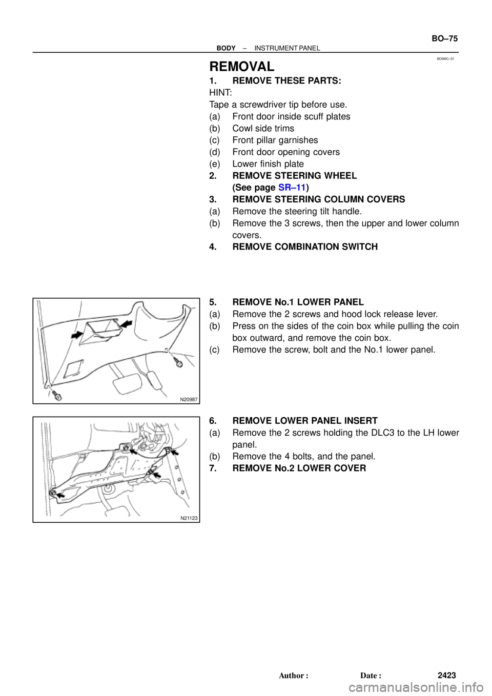
5. REMOVE No.1 LOWER PANEL
(a) Remove the 2 screws and hood lock release lever.
(b) Press on the sides of the coin box while pulling the coin
box outward, and remove the coin box.
(c) Remove the screw, bolt and the No.1 lower panel.
6. REMOVE LOWER PANEL INSERT
(a) Remove the 2 screws holding the DLC3 to the LH lower
panel.
(b) Remove the 4 bolts, and the panel.
7. REMOVE No.2 LOWER COVER
Page 922 of 4592
 Remove the bolt, nut, screw and the instrument panel as-
sembly.
23. REMOVE INSTRUMENT PANEL BRACES
(a) Remove the w")
N20994
N20995
N20996
N20997
BO±78
± BODYINSTRUMENT PANEL
2426 Author�: Date�:
(f) Remove the bolt, nut, screw and the instrument panel as-
sembly.
23. REMOVE INSTRUMENT PANEL BRACES
(a) Remove the wire brackets and connector.
(b) Remove the bolt and connector from the No.1 instrument
panel brace.
(c) w/ Wireless Control:
Remove the nut and the wireless control unit from the
No.1 instrument panel brace.
(d) Remove the nut holding the radio antenna to the No.2
instrument panel brace.
(e) Remove a nut and brace mount bracket.
(f) Remove the 6 nuts, 2 bolts and No.1 and No.2 instrument
panel braces.
24. REMOVE INSTRUMENT PANEL REINFORCEMENT
(a) Remove the connectors from the steering column tube.
(b) Remove the 4 wire brackets and connectors.
(c) Remove the 2 nuts and bolt holding the No.1 Junction Box
(J/B) to the reinforcement.
(d) Remove the 4 nuts and the steering column from the rein-
forcement.
(e) Remove the brake pedal spring from the reinforcement
and brake pedal.
(f) Remove the 4 nuts, 3 bolts and the reinforcement.
Page 1082 of 4592
BR0BR±03
R00327
W04507
BR±68
± BRAKEFRONT SPEED SENSOR
2091 Author�: Date�:
REMOVAL
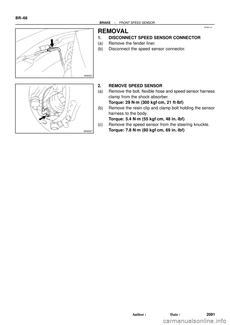
1. DISCONNECT SPEED SENSOR CONNECTOR
(a) Remove the fender liner.
(b) Disconnect the speed sensor connector.
2. REMOVE SPEED SENSOR
(a) Remove the bolt, flexible hose and speed sensor harness
clamp from the shock absorber.
Torque: 29 N´m (300 kgf´cm, 21 ft´lbf)
(b) Remove the resin clip and clamp bolt holding the sensor
harness to the body.
Torque: 5.4 N´m (55 kgf´cm, 48 in.´lbf)
(c) Remove the speed sensor from the steering knuckle.
Torque: 7.8 N´m (80 kgf´cm, 69 in.´lbf)
Page 1227 of 4592

DI±15
250 Author�: Date�:
(b) TOYOTA Enhanced Signals.
TOYOTA hand±held tester displayMeasurement ItemNormal Condition*1
MISFIRE RPMEngine RPM for first misfire rangeMi")
± DIAGNOSTICSENGINE (5S±FE)
DI±15
250 Author�: Date�:
(b) TOYOTA Enhanced Signals.
TOYOTA hand±held tester displayMeasurement ItemNormal Condition*1
MISFIRE RPMEngine RPM for first misfire rangeMisfire 0: 0 rpm
MISFIRE LOADEngine load for first misfire rangeMisfire 0: 0 g/r
INJECTORFuel injection time for cylinder No.1Idling: 2.9 ~ 5.1 ms
IAC DUTY RATIOIntake Air Control Valve Duty Ratio
Opening ratio rotary solenoid type IAC valveIdling: 25 ~ 62 %
STARTER SIGStarter SignalCranking: ON
CTP SIGClosed Throttle Position SignalThrottle fully closed: ON
A/C SIGA/C Switch SignalA/C ON: ON
PNP SIGPark/Neutral Position Switch SignalP or N position: ON
ELECTCL LOAD SIGElectrical Load SignalDefogger S/W ON: ON
STOP LIGHT SWStop Light Switch SignalStop light switch ON: ON
PS OIL PRESS SWPower Steering Oil Pressure Switch SignalTurn steering wheel: ON
FC IDLFuel Cut Idle: Fuel cut when throttle valve fully
closed, during decelerationFuel cut operating: ON
FC TAUFuel Cut TAU: Fuel cut during very light loadFuel cut operating: ON
CYL#1, CYL#2, CYL#3, CYL#4Abnormal revolution variation for each cylinder0 %
IGNITIONTotal number of ignition for every 1,000 revolu-
tions0 ~ 2,000 rpm
EGR SYSTEMEGR system operating conditionIdling: OFF
FUEL PUMPFuel Pump SignalIdling: ON
A/C CUT SIGA/C Cut SignalA/C S/W OFF: ON
A/C MAG CLUTCHA/C Switch SignalA/C ON: ON
EVAP (PURGE) VSVEVAP VSV SignalVSV operating: Avove 30 %
VAPOR PRESS VSVVapor Pressure VSV SignalVSV operating: ON
TOTAL FT B1Total Fuel Trim Bank 1: Average value for fuel
trim system of bank 1Idling: 0.8 ~ 1.2 V
O2 LR B1, S1 *2
Heated Oxygen Sensor Lean Rich Bank 1 Sen-
sor 1: Response time for oxygen sensor output to
switch from lean to rich
Idling after warming up: 0 ~ 1,000 msec.
O2 RL B1, S1 *2
Heated Oxygen Sensor Rich Lean Bank 1 Sen-
sor 1: Response time for oxygen sensor output to
switch from rich to lean
Idling after warming up: 0 ~ 1,000 msec.
*1: If no conditions are specifically stated for ºldlingº, it means the shift lever is at N or P position, the A/C
switch is OFF and all accessory switches are OFF.
*2: Except California Specification vehicles.
Page 1236 of 4592

259 Author�: Date�:
Symbols (Terminals No.)Wiring ColorConditionSTD Voltage (V)
*1GBR
IdlingBelow 3.01
HTAF (E9 ± 2) ± E04 (E9 ± 15)G e BR
IG switch ON9 ~ 14
LO")
DI±24
± DIAGNOSTICSENGINE (5S±FE)
259 Author�: Date�:
Symbols (Terminals No.)Wiring ColorConditionSTD Voltage (V)
*1GBR
IdlingBelow 3.01
HTAF (E9 ± 2) ± E04 (E9 ± 15)G e BR
IG switch ON9 ~ 14
LOCK IN (E9 ± 18)
± E1 (E9 ± 14)W ± L e BRA/C compressor is operatingPulse generation
(See page DI±190)
LOCK (E7 15) E1(E9 14)RWBRA/C indicator light lights upBelow 4.0LOCK (E7 ± 15) ± E1(E9 ± 14)R ± W e BRA/C indicator light does not lights upBelow 1.0
A/C SW (E7 ± 10)RBBRA/C switch ON9 ~ 14A/C SW (E7 10)
± E1 (E9 ± 14)R ± B e BRA/C switch OFFBelow 1.0
PRS (E7 ± 13) ± E1 (E9 ± 14)G e BRA/C pressure is normallyBelow 1.0
THR (E8 10) E2 (E8 9)LRBRIG switch ON, A/C evaporator temp. 0°C (32°F)2.2 ~ 2.6THR (E8 ± 10) ± E2 (E8 ± 9)L ± R e BRIG switch ON, A/C evaporator temp. 15°C (59°F)1.4 ~ 1.8
MGC (E7 21) E01(E9 14)LYBRA/C magnetic clutch ONBelow 1.0MGC (E7 ± 21) ± E01(E9 ± 14)L ± Y e BRA/C magnetic clutch OFF9 ~ 14
* STP (E7 4) E1 (E9 14)GWBRIG switch ON, Brake pedal depressed7.5 ~ 14* STP (E7 ± 4) ± E1 (E9 ± 14)G ± W e BRIG switch ON, Brake pedal releasedBelow 1.5
ELS (E7 2) E1 (E9 14)BRBRDefogger switch and taillight switch ON7.5 ~ 14ELS (E7 ± 2) ± E1 (E9 ± 14)B ± R e BRDefogger switch and taillight switch OFFBelow 1.5
PSSW (E8 ± 12) BLBRIG switch ON9 ~ 14PSSW (E8 12)
± E1 (E9 ± 14)B ± L e BRAt idling, Turn steering wheel to lock positionBelow 3.0
SIL (E7 ± 16) ± E1 (E9 ± 14)W e BRDuring transmissionPulse generation
*: Only for A/T models
*1: Only for California Specification vehicles
Page 1239 of 4592

DI±27
262 Author�: Date�:
Symbols (Terminals No.)Wiring ColorConditionSTD Voltage (V)
*1GBR
IdlingBelow 3.01
HTAF (E9 ± 2) ± E04 (E9 ± 15)G e BR
IG switch ON9 ~ 14
LO")
± DIAGNOSTICSENGINE (5S±FE)
DI±27
262 Author�: Date�:
Symbols (Terminals No.)Wiring ColorConditionSTD Voltage (V)
*1GBR
IdlingBelow 3.01
HTAF (E9 ± 2) ± E04 (E9 ± 15)G e BR
IG switch ON9 ~ 14
LOCK IN (E9 ± 19)
± E1 (E9 ± 24)W ± L e BRA/C compressor is operatingPulse generation
(See page DI±190)
LOCK (E7 ± 20)RWBRA/C indicator light lights upBelow 4.0LOCK (E7 20)
± E1 (E9 ± 24)R ± W e BRA/C indicator light does not lights upBelow 1.0
A/C SW (E7 ± 10)RBBRA/C switch ON9 ~ 14A/C SW (E7 10)
± E1 (E9 ± 24)R ± B e BRA/C switch OFFBelow 1.0
PRS (E7 ± 19) ± E1 (E9 ± 24)G e BRA/C pressure is normallyBelow 1.0
THR (E8 11) E2 (E8 9)LRBRIG switch ON, A/C evaporator temp. 0°C (32°F)2.2 ~ 2.6THR (E8 ± 11) ± E2 (E8 ± 9)L ± R e BRIG switch ON, A/C evaporator temp. 15°C (59°F)1.4 ~ 1.8
MGC (E7 ± 21)LYBRA/C magnetic clutch ONBelow 1.0MGC (E7 21)
± E01 (E9 ± 13)L ± Y e BRA/C magnetic clutch OFF9 ~ 14
* STP (E7 9) E1 (E9 24)GWBRIG switch ON, Brake pedal depressed7.5 ~ 14* STP (E7 ± 9) ± E1 (E9 ± 24)G ± W e BRIG switch ON, Brake pedal releasedBelow 1.5
ELS (E7 13) E1 (E9 24)BRBRDefogger switch and taillight switch ON7.5 ~ 14ELS (E7 ± 13) ± E1 (E9 ± 24)B ± R e BRDefogger switch and taillight switch OFFBelow 1.5
PSSW (E9 ± 4) BLBRIG switch ON9 ~ 14PSSW (E9 4)
± E1 (E9 ± 24)B ± L e BRAt idling, Turn steering wheel to lock positionBelow 3.0
SIL (E7 ± 6) ± E1 (E9 ± 24)W e BRDuring transmissionPulse generation
TACH (E7 ± 7) ± E1 (E9 ± 24)B ± O eBRIdlingPulse generation
KSW (E10 4) E1 (E9 24)LBBRAt the time of inserting keyBelow 1.5KSW (E10 ± 4) ± E1 (E9 ± 24)L ± B e BRIn the condition without key insertedPulse generation
RXCK (E10 ± 3)
± E1 (E9 ± 24)R ± L eBRAt the time of inserting keyPulse generation
CODE (E10 ± 8)
± E1 (E9 ± 24)G ± W eBRAt the time of inserting keyPulse generation
TXCT (E10 ± 1)
± E1 (E9 ± 24)L ± Y eBRAt the time of inserting keyPulse generation
IMLD (E10 ± 1) ± E1 (E9 ± 24)R ± Y eBRIn the condition without key insertedPulse generation
MREL (E10 ± 7)
± E1 (E9 ± 24)B ± W eBRIG switch ON9 ~ 14
IGSW (E7 ± 1) ± E1 (E9 ± 24)B ± ReBRIG switch ON9 ~ 14
*: Only for A/T models
*1: Only for California Specification vehicles
Drive Pinion Bearing Replacer
(09351±32120)Overdrive Bearing Replacer
(09351±32140)Oil Seal Replacer
(09351±32150)Oil Seal Replacer
(09351±321")