Page 1421 of 4592

DI±209
444 Author�: Date�:
(b) TOYOTA Enhanced Signals.
TOYOTA hand±held tester displayMeasurement ItemNormal Condition*
MISFIRE RPMEngine RPM for first misfire rangeM")
± DIAGNOSTICSENGINE (1MZ±FE)
DI±209
444 Author�: Date�:
(b) TOYOTA Enhanced Signals.
TOYOTA hand±held tester displayMeasurement ItemNormal Condition*
MISFIRE RPMEngine RPM for first misfire rangeMisfire 0: 0 rpm
MISFIRE LOADEngine load for first misfire rangeMisfire 0: 0 g/r
INJECTORFuel injection time for cylinder No.1Idling: 1.6 ~ 2.9 ms
IAC DUTY RATIOIntake Air Control Valve Duty Ratio
Opening ratio rotary solenoid type IAC valveIdling: 27 ~ 47 %
STARTER SIGStarter SignalCranking: ON
CTP SIGClosed Throttle Position SignalThrottle Fully Closed: ON
A/C SIGA/C Switch SignalA/C ON: ON
PNP SWPark/Neutral Position Switch SignalP or N position: ON
ELCTRCL LOAD SIGElectrical Load SignalDefogger switch ON: ON
STOP LIGHT SWStop Light Switch SignalStop light switch ON: ON
PS OIL PRESS SWPower Steering Oil Pressure Switch SignalTurn steering wheel: ON
FC IDLFuel Cut Idle: Fuel cut when throttle valve fully
closed, during decelerationFuel cut operating: ON
FC TAUFuel Cut TAU: Fuel cut during very light loadFuel cut operating: ON
CYL#1 ~ CYL#6Abnormal revolution variation for each cylinder0%
IGNITIONTotal number of ignition for every 1,000 revolu-
tions0 ~ 3,000
EGRT GASEGR Gas Temperature Sensor Value
EGR not operating:
Temperature between intake air temp. and
engine coolant temp.
INTAKE CTRL VSVIntake Air Control Valve VSV SignalVSV operating: ON
EGR SYSTEMEGR system operating conditionIdling: OFF
A/C CUT SIGA/C Cut SignalA/C S/W OFF: ON
FUEL PUMPFuel Pump SignalIdling: ON
EVAP (PURGE) VSVEVAP VSV SignalVSV operating: Above 30%
VAPOR PRESS VSVVapor Pressure VSV SignalVSV operating: ON (TANK)
*: If no conditions are specifically stated for ºldlingº, it means the shift lever is at N or P position, the A/C switch
is OFF and all accessory switches are OFF.
Page 1729 of 4592
BR3795
OK NG OK NG
OK NGOK NG
W04200
Normal Signal Waveform
1 V / Division2 m/s / DivisionGND
± DIAGNOSTICSANTI±LOCK BRAKE SYSTEM (DENSO Made)
DI±517
752 Author�: Date�:
2 Check for open and short circuit in harness and connector between each speed
sensor and ECU (See page IN±31).
NG Repair or replace harness or connector.
OK
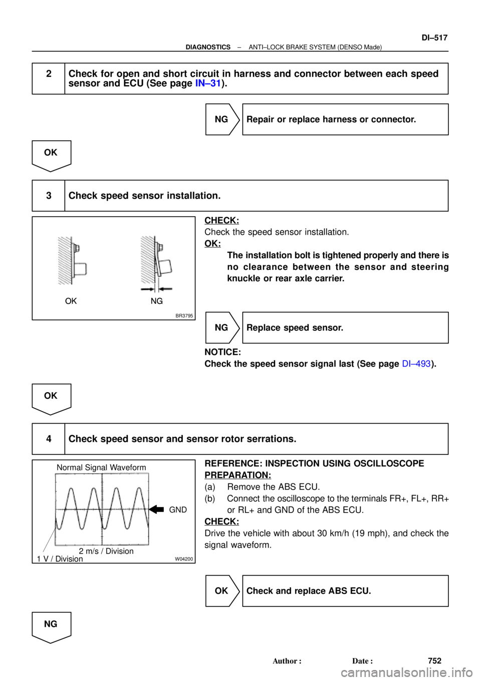
3 Check speed sensor installation.
CHECK:
Check the speed sensor installation.
OK:
The installation bolt is tightened properly and there is
no clearance between the sensor and steering
knuckle or rear axle carrier.
NG Replace speed sensor.
NOTICE:
Check the speed sensor signal last (See page DI±493).
OK
4 Check speed sensor and sensor rotor serrations.
REFERENCE: INSPECTION USING OSCILLOSCOPE
PREPARATION:
(a) Remove the ABS ECU.
(b) Connect the oscilloscope to the terminals FR+, FL+, RR+
or RL+ and GND of the ABS ECU.
CHECK:
Drive the vehicle with about 30 km/h (19 mph), and check the
signal waveform.
OK Check and replace ABS ECU.
NG
Page 1767 of 4592
BR3795
OK NG OK NG
OK NGOK NG
R00948
± DIAGNOSTICSANTI±LOCK BRAKE SYSTEM (BOSCH Made)
DI±555
790 Author�: Date�:
2 Check for open and short circuit in harness and connector between each speed
sensor and ECU (See page IN±31).
NG Repair or replace harness or connector.
OK
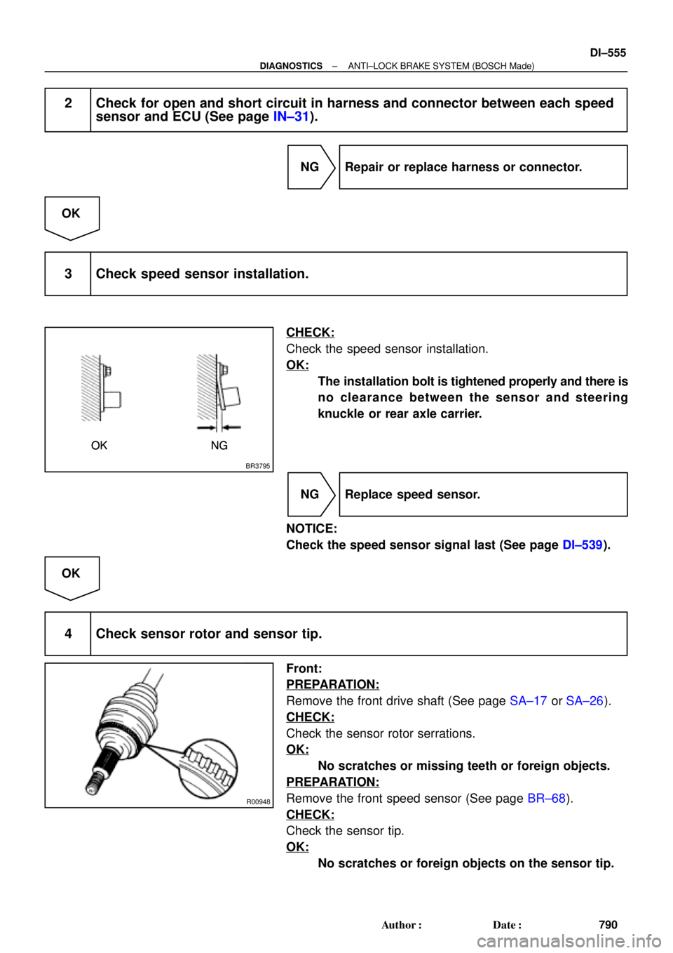
3 Check speed sensor installation.
CHECK:
Check the speed sensor installation.
OK:
The installation bolt is tightened properly and there is
no clearance between the sensor and steering
knuckle or rear axle carrier.
NG Replace speed sensor.
NOTICE:
Check the speed sensor signal last (See page DI±539).
OK
4 Check sensor rotor and sensor tip.
Front:
PREPARATION:
Remove the front drive shaft (See page SA±17 or SA±26).
CHECK:
Check the sensor rotor serrations.
OK:
No scratches or missing teeth or foreign objects.
PREPARATION:
Remove the front speed sensor (See page BR±68).
CHECK:
Check the sensor tip.
OK:
No scratches or foreign objects on the sensor tip.
Page 1808 of 4592
BR3795
OK NG OK NG
OK NGOK NG
W04200
Normal Signal Waveform
1 V / Division2 m/s / DivisionGND
DI±596
± DIAGNOSTICSABS & TRACTION CONTROL SYSTEM
831 Author�: Date�:
2 Check for open and short circuit in harness and connector between each speed
sensor and ECU (See page IN±31).
NG Repair or replace harness or connector.
OK
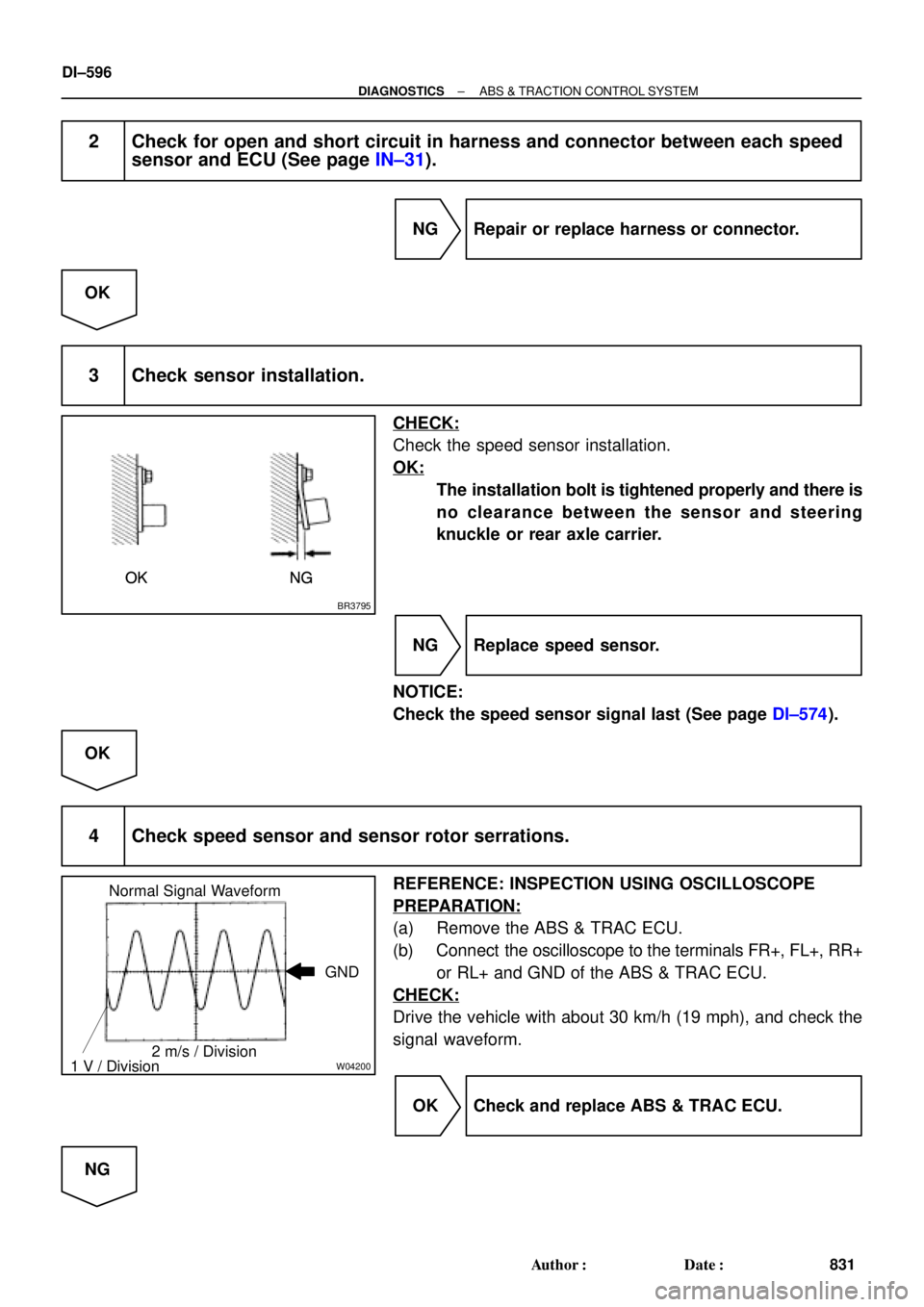
3 Check sensor installation.
CHECK:
Check the speed sensor installation.
OK:
The installation bolt is tightened properly and there is
no clearance between the sensor and steering
knuckle or rear axle carrier.
NG Replace speed sensor.
NOTICE:
Check the speed sensor signal last (See page DI±574).
OK
4 Check speed sensor and sensor rotor serrations.
REFERENCE: INSPECTION USING OSCILLOSCOPE
PREPARATION:
(a) Remove the ABS & TRAC ECU.
(b) Connect the oscilloscope to the terminals FR+, FL+, RR+
or RL+ and GND of the ABS & TRAC ECU.
CHECK:
Drive the vehicle with about 30 km/h (19 mph), and check the
signal waveform.
OK Check and replace ABS & TRAC ECU.
NG
Page 1841 of 4592
± DIAGNOSTICSSUPPLEMENTAL RESTRAINT SYSTEM
DI±629
864 Author�: Date�:
7. RELEASE METHOD OF AIRBAG ACTIVATION PRE-
VENTION MECHANISM
An airbag activation prevention mechanism is built into the con-
nector for the squib circuit of the SRS.
When release of the airbag activation prevention mechanism is
directed in the troubleshooting procedure, as shown in the il-
lustration of the connectors on the next pages, insert paper
which is the same thickness as the male terminal, between the
terminal and the short spring.
CAUTION:
Never release the airbag activation prevention mechanism
on the steering wheel pad connector.
NOTICE:
�Do not release the airbag activation prevention mech-
anism unless specifically directed by the trouble-
shooting procedure.
�If the inserted paper is too thick the terminal and short
spring may be damaged, so always use paper with
the same thickness as the male terminal.
Page 1842 of 4592
H08316
TMC made :
Side Airbag Assembly (LH)
(Squib) Side Airbag Sensor (LH)Side Airbag Sensor (RH)Side Airbag Assembly (RH)
(Squib)
Seat Belt
Pretensioner (RH)
Airbag Sensor
AssemblyFront Passenger Airbag Assembly (Squib)
Spiral Cable
No.1 J/B 2
37 8
10
11
12
13
1
4
5
6
9
Steering Wheel
Pad (Squib) Front Airbag Sensor (RH)
Front Airbag Sensor (LH)
Seat Belt
Pretensioner (LH) 14
15
16
DI±630
± DIAGNOSTICSSUPPLEMENTAL RESTRAINT SYSTEM
865 Author�: Date�:
Page 1843 of 4592
H08247
Airbag Sensor
AssemblySide Airbag Assembly (RH)
(Squib)
Seat Belt
Pretensioner (RH)
Side Airbag Sensor (RH)
Front Passenger Airbag
Assembly (Squib)
Spiral Cable
Steering Wheel
Pad (Squib)
No.1 J / B
Side Airbag Sensor (LH)
Side Airbag Assembly (LH)
(Squib)1
2
3
4
5
6
7
14
9
10
1112
13
8
15 TMMK made :
Seat Belt
Pretensioner (LH)
16
17
18
Front Airbag Sensor (RH)
Front Airbag Sensor (LH)
± DIAGNOSTICSSUPPLEMENTAL RESTRAINT SYSTEM
DI±631
866 Author�: Date�:
Page 1845 of 4592

DI1AZ±04
± DIAGNOSTICSSUPPLEMENTAL RESTRAINT SYSTEM
DI±633
868 Author�: Date�:
DIAGNOSTIC TROUBLE CODE CHART
If a malfunction code is displayed during the DTC check, check the circuit listed for that code in the table
below (Proceed to the page given for that circuit.).
DTC No.
(See Page)Detection ItemTrouble AreaSRS
Warning Light
B0100/13
(DI±640)
�Short in D squib circuit�Steering wheel pad (squib)
�Spiral cable
�Airbag sensor assembly
�Wire harness
ON
B0101/14
(DI±645)
�Open in D squib circuit�Steering wheel pad (squib)
�Spiral cable
�Airbag sensor assembly
�Wire harness
ON
B0102/11
(DI±649)
�Short in D squib circuit (to Ground)�Steering wheel pad (squib)
�Spiral cable
�Airbag sensor assembly
�Wire harness
ON
B0103/12
(DI±653)
�Short in D squib circuit (to B+)�Steering wheel pad (squib)
�Spiral cable
�Airbag sensor assembly
�Wire harness
ON
B0105/53
(DI±657)�Short in P squib circuit�Front passenger airbag assembly (squib)
�Airbag sensor assembly
�Wire harness
ON
B0106/54
(DI±661)�Open in P squib circuit�Front passenger airbag assembly (squib)
�Airbag sensor assembly
�Wire harness
ON
B0107/51
(DI±664)�Short in P squib circuit (to Ground)�Front passenger airbag assembly (squib)
�Airbag sensor assembly
�Wire harness
ON
B0108/52
(DI±667)�Short in P squib circuit (to B+)�Front passenger airbag assembly (squib)
�Airbag sensor assembly
�Wire harness
ON
TMC made:
B0110/43
(DI±670)�Short in side squib (RH) circuit�Side airbag assembly RH (squib)
�Airbag sensor assembly
�Wire harness
Blink
TMMK made:
B0110/43
(DI±674)�Short in side squib (RH) circuit�Side airbag assembly RH (squib)
�Airbag sensor assembly
�Wire harness
�Sub wire harness
Blink
TMC made:
B0111/44
(DI±679)�Open in side squib (RH) circuit�Side airbag assembly RH (squib)
�Airbag sensor assembly
�Wire harness
Blink
TMMK made:
B0111/44
(DI±682)�Open in side squib (RH) circuit�Side airbag assembly RH (squib)
�Airbag sensor assembly
�Wire harness
�Sub wire harness
Blink
TMC made:
B0112/41
(DI±686)�Short in side squib (RH) circuit
(to Ground)�Side airbag assembly RH (squib)
�Airbag sensor assembly
�Wire harness
Blink


(Squib) Side Airbag Sensor (LH)Side Airbag Sensor (RH)Side Airbag Assembly (RH)
(Squib)
Seat Belt
Pretensioner (RH)
Airbag Sensor
AssemblyFront Passenger Ai")

(Squib)
Seat Belt
Pretensioner (RH)
Side Airbag Sensor (RH)
Front Passenger Airbag
Assembly (Squib)
Spiral Cable
Steering Wheel
Pad (Squib)
No.1")