Page 1848 of 4592
DI1B0±04
H08283
Combination Meter
(Warning Light)Steering Wheel Pad
(with Airbag)
Airbag Sensor AssemblyFront Passenger
Airbag Assembly
Side Airbag Assembly
(LH)
Side Airbag Sensor
Assembly (LH)
Seat Belt
Pretensioner (LH)Side Airbag Assembly (RH)
Side Airbag Sensor Assembly (RH)
Seat Belt
Pretensioner (RH) Front Airbag
Sensor (LH)Front Airbag Sensor (RH)
Spiral Cable
DI±636
± DIAGNOSTICSSUPPLEMENTAL RESTRAINT SYSTEM
871 Author�: Date�:
PARTS LOCATION
Page 1852 of 4592
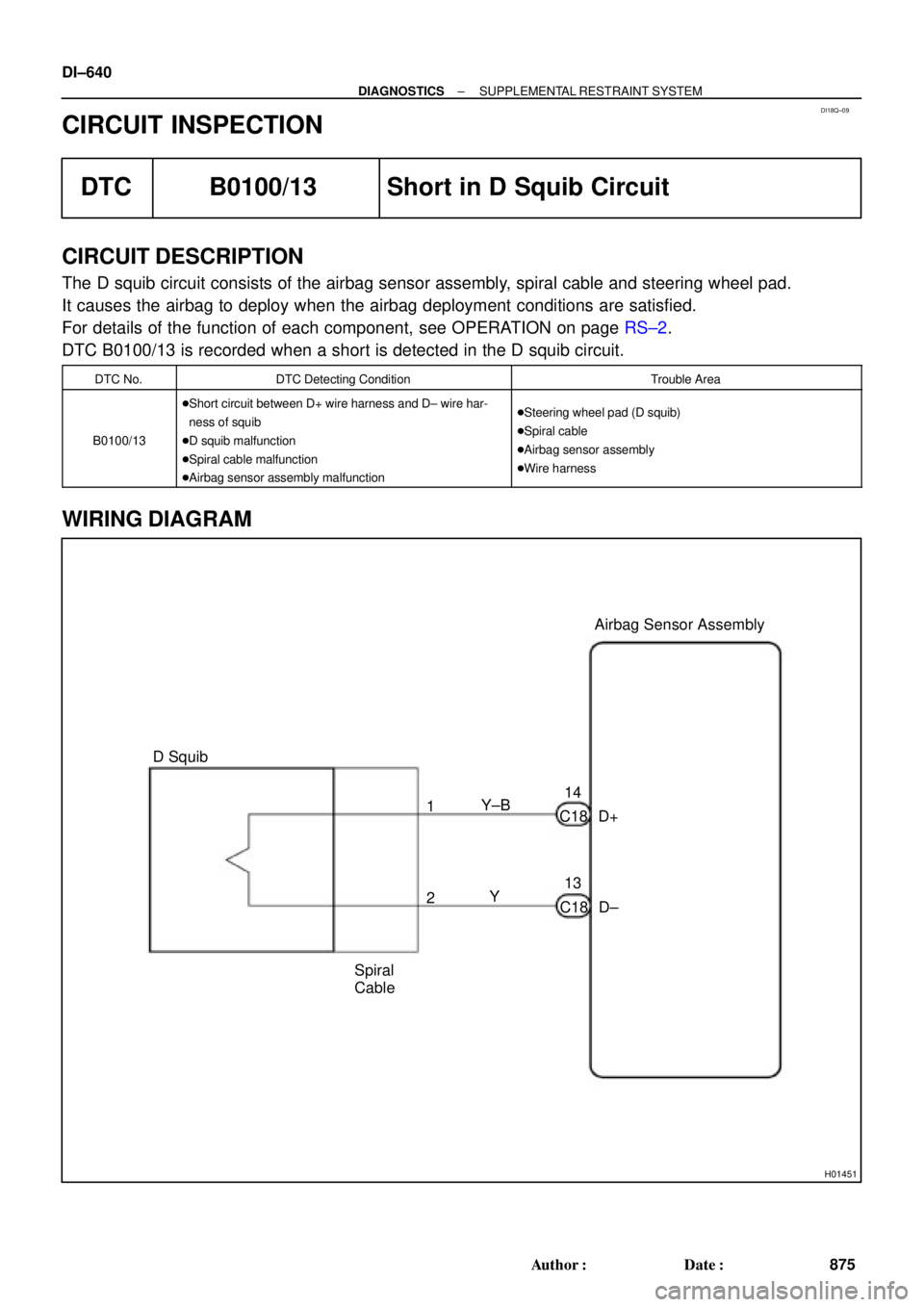
DI18Q±09
H01451
Y±B
D+ C1814Airbag Sensor Assembly
13
C18 D± Y 1
2
Spiral
Cable D Squib DI±640
± DIAGNOSTICSSUPPLEMENTAL RESTRAINT SYSTEM
875 Author�: Date�:
CIRCUIT INSPECTION
DTC B0100/13 Short in D Squib Circuit
CIRCUIT DESCRIPTION
The D squib circuit consists of the airbag sensor assembly, spiral cable and steering wheel pad.
It causes the airbag to deploy when the airbag deployment conditions are satisfied.
For details of the function of each component, see OPERATION on page RS±2.
DTC B0100/13 is recorded when a short is detected in the D squib circuit.
DTC No.DTC Detecting ConditionTrouble Area
B0100/13
�Short circuit between D+ wire harness and D± wire har-
ness of squib
�D squib malfunction
�Spiral cable malfunction
�Airbag sensor assembly malfunction�Steering wheel pad (D squib)
�Spiral cable
�Airbag sensor assembly
�Wire harness
WIRING DIAGRAM
Page 1853 of 4592
R14286H01001H01134
D SquibSpiral
Cable
Airbag
Sensor
Assembly
D+ u"
(±) (+)D±
± DIAGNOSTICSSUPPLEMENTAL RESTRAINT SYSTEM
DI±641
876 Author�: Date�:
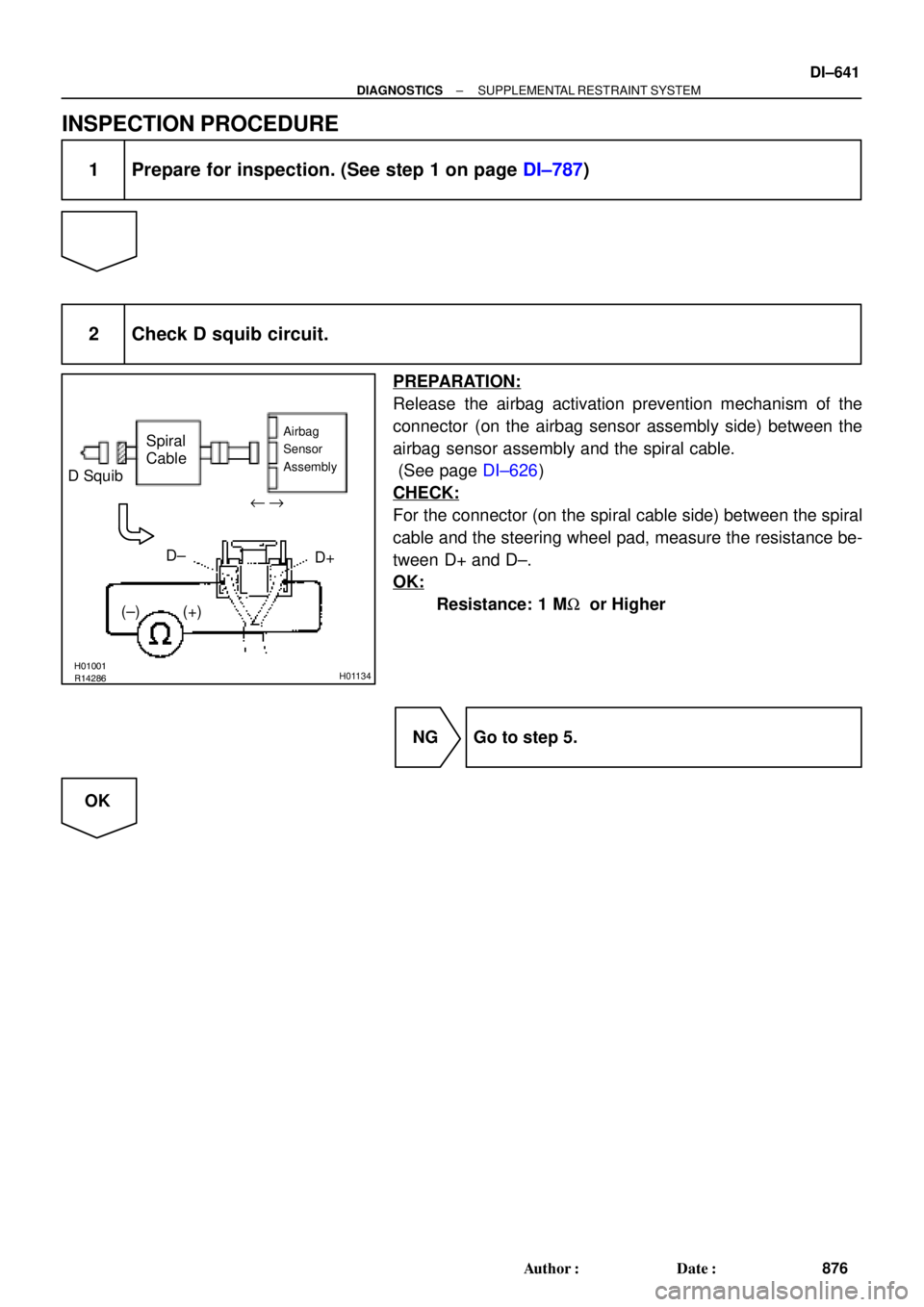
INSPECTION PROCEDURE
1 Prepare for inspection. (See step 1 on page DI±787)
2 Check D squib circuit.
PREPARATION:
Release the airbag activation prevention mechanism of the
connector (on the airbag sensor assembly side) between the
airbag sensor assembly and the spiral cable.
(See page DI±626)
CHECK:
For the connector (on the spiral cable side) between the spiral
cable and the steering wheel pad, measure the resistance be-
tween D+ and D±.
OK:
Resistance: 1 MW or Higher
NG Go to step 5.
OK
Page 1855 of 4592

AB0118
R13006AB0119FI1390
H01003H01136
D SquibSpiral
CableAirbag
Sensor
Assembly
E1 TcACC ON
or
DTC B0100/13
DLC1
" u
± DIAGNOSTICSSUPPLEMENTAL RESTRAINT SYSTEM
DI±643
878 Author�: Date�:
4 Check D squib.
PREPARATION:
(a) Turn ignition switch to LOCK.
(b) Disconnect negative (±) terminal cable from the battery,
and wait at least for 90 seconds.
(c) Connect the steering wheel pad connector.
(d) Connect negative (±) terminal cable to the battery, and
wait at least for 2 seconds.
CHECK:
(a) Turn ignition switch to LOCK, and wait at least for 20 se-
conds.
(b) Turn ignition switch to ACC or ON, and wait at least for 20
seconds.
(c) Clear DTC stored in memory.
(See page DI±626)
(d) Turn ignition switch to LOCK, and wait at least for 20 se-
conds.
(e) Turn ignition switch to ACC or ON, and wait at least for 20
seconds.
(f) Check DTC.
(See page DI±626)
OK:
DTC B0100/13 is not output.
HINT:
Codes other than code B0100/13 may be output at this time, but
they are not relevant to this check.
NG Replace steering wheel pad.
OK
From the results of the above inspection, the malfunctioning part can now be considered normal.
To make sure of this, use the simulation method to check.
Page 1856 of 4592
 (+)D±
R14286H01004H01138
D SquibSpiral
Cable
Airbag
Sensor
Assembly
D+ u\"
(±) (+)D±
DI±644
± DIAGNOSTICSSUPPLEMENTAL RESTR")
R14286H01000H01137
D SquibSpiral
Cable
Airbag
Sensor
Assembly
D+ u"
(±) (+)D±
R14286H01004H01138
D SquibSpiral
Cable
Airbag
Sensor
Assembly
D+ u"
(±) (+)D±
DI±644
± DIAGNOSTICSSUPPLEMENTAL RESTRAINT SYSTEM
879 Author�: Date�:
5 Check spiral cable.
PREPARATION:
(a) Disconnect the connector between the airbag sensor as-
sembly and the spiral cable.
(b) Release the airbag activation prevention mechanism of
the spiral cable connector on the airbag sensor assembly
side. (See page DI±626)
CHECK:
For the connector (on the spiral cable side) between the spiral
cable and the steering wheel pad, measure the resistance be-
tween D+ and D±.
OK:
Resistance: 1 MW or Higher
NG Repair or replace spiral cable.
OK
6 Check harness between airbag sensor assembly and spiral cable.
PREPARATION:
Release the airbag activation prevention mechanism of the
connector (on the airbag sensor assembly side) between the
airbag sensor assembly and the spiral cable. (See page
DI±626)
CHECK:
For the connector (on the spiral cable side) between the airbag
sensor assembly and the spiral cable, measure the resistance
between D+ and D±.
OK:
Resistance: 1 MW or Higher
NG Repair or replace harness or connector be-
tween airbag sensor assembly and spiral cable.
OK
From the results of the above inspection, the malfunctioning part can now be considered normal.
To make sure of this, use the simulation method to check.
Page 1857 of 4592
 (+)D±
± DIAGNOSTICSSUPPLEMENTAL RESTRAINT SYSTEM
DI±645
880 Author�: Date�:
DTC B0101/14 Open in D Squib Circuit
CIRCUIT DES")
R14286H01001H01139
D SquibSpiral
Cable
Airbag
Sensor
Assembly
D+ u"
(±) (+)D±
± DIAGNOSTICSSUPPLEMENTAL RESTRAINT SYSTEM
DI±645
880 Author�: Date�:
DTC B0101/14 Open in D Squib Circuit
CIRCUIT DESCRIPTION
The D squib circuit consists of the airbag sensor assembly, spiral cable and steering wheel pad.
It causes the airbag to deploy when the airbag deployment conditions are satisfied.
For details of the function of each component, see OPERATION on page RS±2.
DTC B0101/14 is recorded when an open is detected in the D squib circuit.
DTC No.DTC Detecting ConditionTrouble Area
B0101/14
�Open circuit in D+ wire harness or D± wire harness of
squib
�D squib malfunction
�Spiral cable malfunction
�Airbag sensor assembly malfunction�Steering wheel pad (D squib)
�Spiral cable
�Airbag sensor assembly
�Wire harness
WIRING DIAGRAM
See page DI±640.
INSPECTION PROCEDURE
1 Prepare for inspection. (See step 1 on page DI±787)
2 Check D squib circuit.
CHECK:
For the connector (on the spiral cable side) between the spiral
cable and the steering wheel pad, measure the resistance be-
tween D+ and D±.
OK:
Resistance: Below 1 W
NG Go to step 5.
OK
DI18R±16
Page 1858 of 4592

AB0118
R13006AB0069
AB0119W02044
H01002
H01140
D SquibSpiral
CableAirbag
Sensor
Assembly
E1TcACCON
or
DTC B0101/14 DLC1"u
D+D±
DI±646
± DIAGNOSTICSSUPPLEMENTAL RESTRAINT SYSTEM
881 Author�: Date�:
3 Check airbag sensor assembly.
PREPARATION:
(a) Connect the connector to the airbag sensor assembly.
(b) Using a service wire, connect D+ and D± of the connector
(on the spiral cable side) between the spiral cable and the
steering wheel pad.
(c) Connect negative (±) terminal cable to the battery, and
wait at least for 2 seconds.
CHECK:
(a) Turn ignition switch to ACC or ON, and wait at least for 20
seconds.
(b) Clear DTC stored in memory.
(See page DI±626)
(c) Turn ignition switch to LOCK, and wait at least for 20 se-
conds.
(d) Turn ignition switch to ACC or ON, and wait at least for 20
seconds.
(e) Check DTC.
(See page DI±626)
OK:
DTC B0101/14 is not output.
HINT:
Codes other than code B0101/14 may be output at this time, but
they are not relevant to this check.
NG Replace airbag sensor assembly.
OK
Page 1859 of 4592

W02044
H01003AB0118
R13006AB0119H01141
"u D Squib
Spiral
CableAirbag
Sensor
Assembly
E1TcACCON
or
DTC B0101/14 DLC1
± DIAGNOSTICSSUPPLEMENTAL RESTRAINT SYSTEM
DI±647
882 Author�: Date�:
4 Check D squib.
PREPARATION:
(a) Turn ignition switch to LOCK.
(b) Disconnect negative (±) terminal cable from the battery,
and wait at least for 90 seconds.
(c) Connect the steering wheel pad connector.
(d) Connect negative (±) terminal cable to the battery, and
wait at least for 2 seconds.
CHECK:
(a) Turn ignition switch to ACC or ON, and wait at least for 20
seconds.
(b) Clear DTC stored in memory.
(See page DI±626)
(c) Turn ignition switch to LOCK, and wait at least for 20 se-
conds.
(d) Turn ignition switch to ACC or ON, and wait at least for 20
seconds.
(e) Check DTC.
(See page DI±626)
OK:
DTC B0101/14 is not output.
HINT:
Codes other than code B0101/14 may be output at this time, but
they are not relevant to this check.
NG Replace steering wheel pad.
OK
From the results of the above inspection, the malfunctioning part can now be considered normal.
To make sure of this, use the simulation method to check.
Steering Wheel Pad
(with Airbag)
Airbag Sensor AssemblyFront Passenger
Airbag Assembly
Side Airbag Assembly
(LH)
Side Airbag Sensor
Assembly (LH)
Seat")