Page 2000 of 4592

H01026H06508H06509
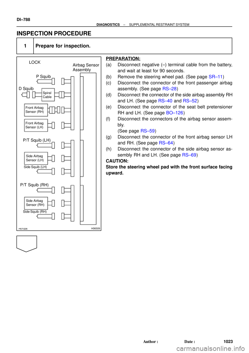
LOCK
Airbag Sensor
Assembly
P Squib
D Squib
P/T Squib (LH)
Side Squib (LH)
P/T Squib (RH)
Side Squib (RH)Spiral
Cable
Side Airbag
Sensor (LH)
Side Airbag
Sensor (RH) Front Airbag
Sensor (LH) Front Airbag
Sensor (RH)
DI±788
± DIAGNOSTICSSUPPLEMENTAL RESTRAINT SYSTEM
1023 Author�: Date�:
INSPECTION PROCEDURE
1 Prepare for inspection.
PREPARATION:
(a) Disconnect negative (±) terminal cable from the battery,
and wait at least for 90 seconds.
(b) Remove the steering wheel pad. (See page SR±11)
(c) Disconnect the connector of the front passenger airbag
assembly. (See page RS±28)
(d) Disconnect the connector of the side airbag assembly RH
and LH. (See page RS±40 and RS±52)
(e) Disconnect the connector of the seat belt pretensioner
RH and LH. (See page BO±126)
(f) Disconnect the connectors of the airbag sensor assem-
bly.
(See page RS±59)
(g) Disconnect the connector of the front airbag sensor LH
and RH. (See page RS±64)
(h) Disconnect the connector of the side airbag sensor as-
sembly RH and LH. (See page RS±69)
CAUTION:
Store the steering wheel pad with the front surface facing
upward.
Page 2001 of 4592

AB0119H01298H01299
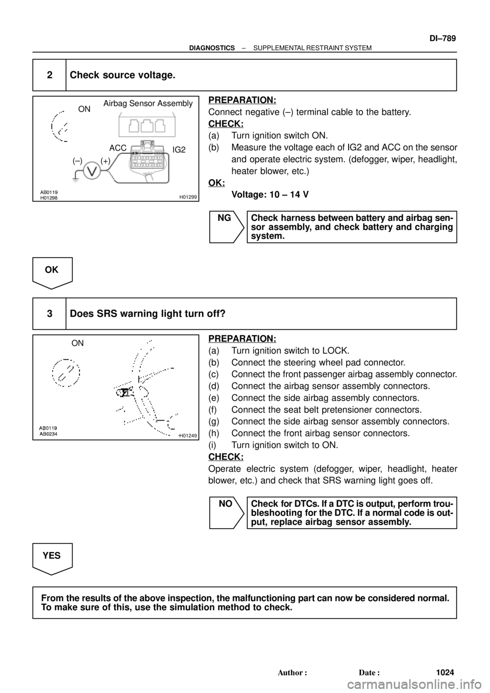
Airbag Sensor Assembly
ON
ACC
IG2
(+) (±)
H01249
ON
± DIAGNOSTICSSUPPLEMENTAL RESTRAINT SYSTEM
DI±789
1024 Author�: Date�:
2 Check source voltage.
PREPARATION:
Connect negative (±) terminal cable to the battery.
CHECK:
(a) Turn ignition switch ON.
(b) Measure the voltage each of IG2 and ACC on the sensor
and operate electric system. (defogger, wiper, headlight,
heater blower, etc.)
OK:
Voltage: 10 ± 14 V
NG Check harness between battery and airbag sen-
sor assembly, and check battery and charging
system.
OK
3 Does SRS warning light turn off?
PREPARATION:
(a) Turn ignition switch to LOCK.
(b) Connect the steering wheel pad connector.
(c) Connect the front passenger airbag assembly connector.
(d) Connect the airbag sensor assembly connectors.
(e) Connect the side airbag assembly connectors.
(f) Connect the seat belt pretensioner connectors.
(g) Connect the side airbag sensor assembly connectors.
(h) Connect the front airbag sensor connectors.
(i) Turn ignition switch to ON.
CHECK:
Operate electric system (defogger, wiper, headlight, heater
blower, etc.) and check that SRS warning light goes off.
NO Check for DTCs. If a DTC is output, perform trou-
bleshooting for the DTC. If a normal code is out-
put, replace airbag sensor assembly.
YES
From the results of the above inspection, the malfunctioning part can now be considered normal.
To make sure of this, use the simulation method to check.
Page 2106 of 4592
N16045
3 4
DI±894
± DIAGNOSTICSCRUISE CONTROL SYSTEM
1129 Author�: Date�:
3 Check control switch.
PREPARATION:
(a) Remove steering wheel center pad.
(b) Disconnect the control switch connector.
CHECK:
Measure resistance between terminals 3 and 4 of control switch
connector when control switch is operated.
Switch positionResistance (W)
Neutral8 (No continuity)
RES/ACC50 ± 80
SET/COAST180 ± 220
CANCEL400 ± 440
NG Replace control switch.
OK
4Check harness and connector between cruise control ECU and cruise control switch,
cruise control switch and body ground (See page
IN±31).
NG Repair or replace harness or connector.
OK
5 Input signal check (See step 1).
OK Wait and see.
NG
Check and replace cruise control ECU
(See page IN±31).
Page 2127 of 4592
N15969
35
± DIAGNOSTICSCRUISE CONTROL SYSTEM
DI±913
1148 Author�: Date�:
2 Check main switch continuity.
PREPARATION:
(a) Remove steering wheel center pad. (See page SR±11)
(b) Disconnect the control switch connector.
CHECK:
Check continuity between terminals 3 and 5 of control switch
connector when main switch is held ON and OFF.
OK:
Switch positionTester connectionSpecified condition
OFF3 ± 5No continuity
Hold ON3 ± 5Continuity
NG Replace control switch.
OK
3 Check harness and connector between cruise control ECU and main switch
(See page IN±31).
NG Repair or replace harness or connector.
OK
Check and replace cruise control ECU
(See page IN±31).
Page 2163 of 4592

DI±12
± DIAGNOSTICSENGINE
SHORT FT #1
Short±term Fuel Trim Bank 10 ± 20 %
LONG FT #1Long±term Fuel Trim Bank 10 ± 20 %
ENGINE SPDEngine SpeedIdling: 650 ± 750 rpm
VEHICLE SPDVehicle SpeedVehicle Stopped: 0 km/h (0 mph)
IGN ADVANCEIgnition Advance: Ignition Timing of Cylinder No.1Idling: BTDC 0 ± 10°
INTAKE AIRIntake Air Temp. Sensor ValueEquivalent to Ambient Temp.
MAPAbsolute Pressure inside Intake ManifoldIdling: 20 ± 51 kPa
Racing without load (2,500 rpm): 17 ± 48 kPa
THROTTLE POSVoltage Output of Throttle Position Sensor Calcu-
lated as a percentage: 0 V "0 %, 5 V "100 %Throttle Fully Closed: 6 ± 16 %
Throttle Fully Open: 64 ± 98 %
O2S B1 S1Voltage Output of Heated Oxygen Sensor Bank 1
Sensor 1Idling: 0.1 ± 0.9 V (0.56 ± 0.76 V*2)
O2FT B1 S1Heated Oxygen Sensor Fuel Trim Bank 1 Sensor
1 (Same as SHORT FT #1)0 ± 20 %
A/FS B1 S1Voltage Output of A/F SensorIdling: 2.8 ± 3.8 V
A/FFT B1 S1A/F Sensor Fuel Trim (Same as SHORT FT #1)0 ± 20 %
O2S B1 S2Voltage Output of Heated Oxygen Sensor Bank 1
Sensor 2Driving at 50 km/h (31 mph): 0.05 ± 0.95 V
*1: If no conditions are specifically stated for ºldlingº, it means the shift lever is at N or P position, the A/C
switch is OFF and all accessory switches are OFF.
*
2: When you use the OBD II scan tool (excluding TOYOTA hand±held tester).
(b) TOYOTA Enhanced Signals.
TOYOTA hand±held tester displayMeasurement ItemNormal Condition*
MISFIRE RPMEngine RPM for first misfire rangeMisfire 0: 0 rpm
MISFIRE LOADEngine load for first misfire rangeMisfire 0: 0 g/r
INJECTORFuel injection time for cylinder No.1Idling: 2.9 ± 5.1 ms
IAC DUTY RATIOIntake Air Control Valve Duty Ratio
Opening ratio rotary solenoid type IAC valveIdling: 25 ± 62 %
STARTER SIGStarter SignalCranking: ON
CTP SIGClosed Throttle Position SignalThrottle fully closed: ON
A/C SIGA/C Switch SignalA/C ON: ON
PNP SIGPark/Neutral Position Switch SignalP or N position: ON
ELECTCL LOAD SIGElectrical Load SignalDefogger S/W ON: ON
STOP LIGHT SWStop Light Switch SignalStop light switch ON: ON
PS OIL PRESS SWPower Steering Oil Pressure Switch SignalTurn steering wheel: ON
FC IDLFuel Cut Idle: Fuel cut when throttle valve fully
closed, during decelerationFuel cut operating: ON
FC TAUFuel Cut TAU: Fuel cut during very light loadFuel cut operating: ON
CYL#1, CYL#2, CYL#3, CYL#4Abnormal revolution variation for each cylinder0 %
IGNITIONTotal number of ignition for every 1,000 revolu-
tions0 ± 2,000
EGR SYSTEMEGR system operating conditionIdling: OFF
FUEL PUMPFuel Pump SignalIdling: ON
A/C CUT SIGA/C Cut SignalA/C S/W OFF: ON
A/C MAG CLUTCHA/C Switch SignalA/C ON: ON
EVAP (PURGE) VSVEVAP VSV SignalVSV operating: Avove 30 %
Page 2353 of 4592
BR3795
OK NG OK NG
OK NGOK NG
W04200
Normal Signal Waveform
1 V / Division2 m/s / DivisionGND
± DIAGNOSTICSANTI±LOCK BRAKE SYSTEM
DI±201
2 Check for open and short circuit in harness and connector between each speed
sensor and ECU (See page IN±29).
NG Repair or replace harness or connector.
OK
3 Check speed sensor installation.
CHECK:
Check the speed sensor installation.
OK:
The installation bolt is tightened properly and there is
no clearance between the sensor and steering
knuckle or rear axle carrier.
NG Replace speed sensor.
NOTICE:
Check the speed sensor signal last (See page DI±177).
OK
4 Check speed sensor and sensor rotor serrations.
REFERENCE: INSPECTION USING OSCILLOSCOPE
PREPARATION:
(a) Remove the ABS ECU.
(b) Connect the oscilloscope to the terminals FR+, FL+, RR+
or RL+ and GND of the ABS ECU.
CHECK:
Drive the vehicle with about 30 km/h (19 mph), and check the
signal waveform.
OK Check and replace ABS ECU.
NG
Page 2378 of 4592
DI±226
± DIAGNOSTICSSUPPLEMENTAL RESTRAINT SYSTEM
7. RELEASE METHOD OF AIRBAG ACTIVATION PRE-
VENTION MECHANISM
An airbag activation prevention mechanism is built into the con-
nector for the squib circuit of the SRS.
When release of the airbag activation prevention mechanism is
directed in the troubleshooting procedure as shown in the il-
lustration of the connectors on the next pages, insert paper
which has the same thickness as the male terminal, between
the terminal and the short spring.
CAUTION:
Never release the airbag activation prevention mechanism
on the steering wheel pad connector.
NOTICE:
�Do not release the airbag activation prevention mech-
anism unless specifically directed by the trouble-
shooting procedure.
�If the inserted paper is too thick the terminal and short
spring may be damaged, so always use paper with
the same thickness as the male terminal.
Page 2379 of 4592
H02720
Airbag Sensor
AssemblyFront Passenger Airbag
Assembly (Squib)
Steering Wheel
Pad (Squib)
No.1 J/B
Pretensioner (LH) Spiral Cable 2
35 4
67 1
8
9
10
Front Airbag Sensor (RH)
Front Airbag Sensor (LH) 11
Pretensioner (RH)
12
± DIAGNOSTICSSUPPLEMENTAL RESTRAINT SYSTEM
DI±227