Page 2402 of 4592
AB0119
R14288H01000
H01133
D SquibSpiral
Cable
Airbag
Sensor
Assembly
D+ u"
(±) (+)ON
H01004R14288
AB0119
H08261
D SquibSpiral
Cable
(±) (+)D+
Airbag
Sensor
Assembly
ON
DI±250
± DIAGNOSTICSSUPPLEMENTAL RESTRAINT SYSTEM
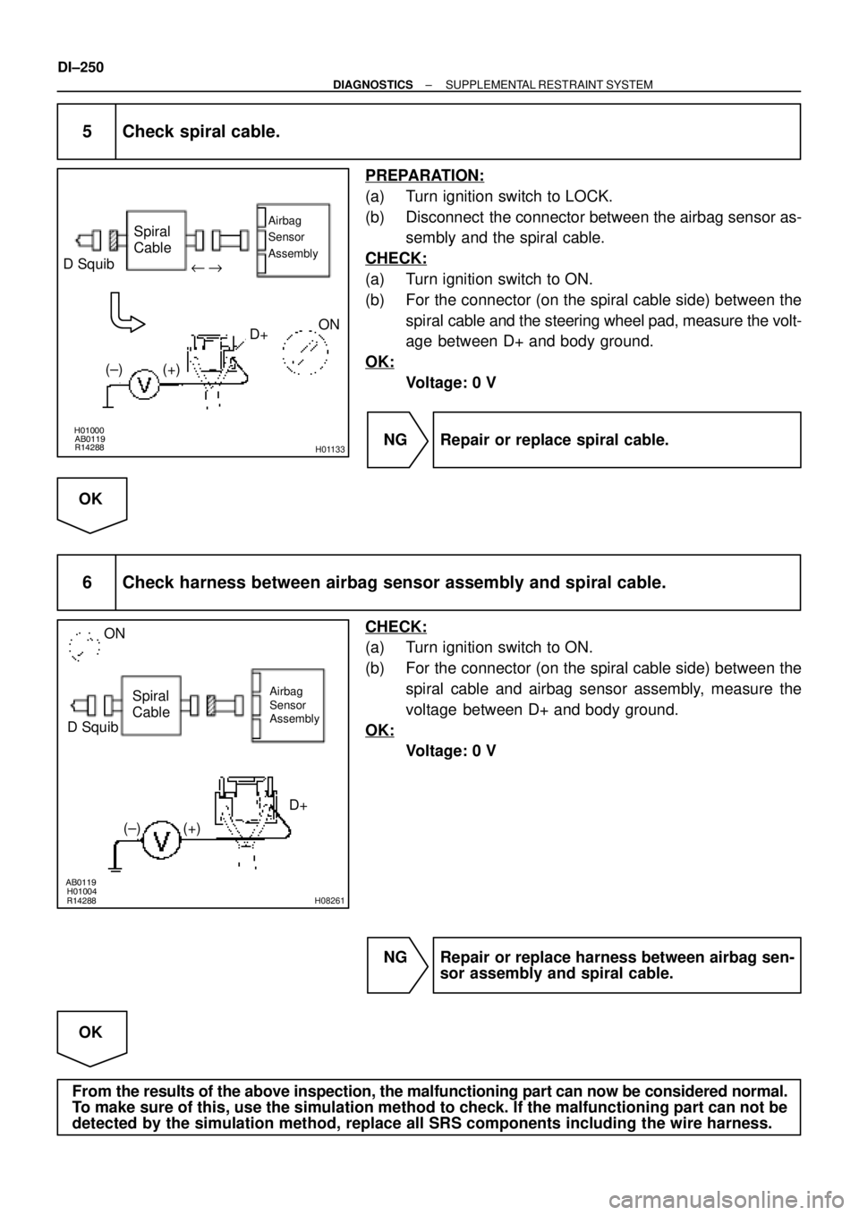
5 Check spiral cable.
PREPARATION:
(a) Turn ignition switch to LOCK.
(b) Disconnect the connector between the airbag sensor as-
sembly and the spiral cable.
CHECK:
(a) Turn ignition switch to ON.
(b) For the connector (on the spiral cable side) between the
spiral cable and the steering wheel pad, measure the volt-
age between D+ and body ground.
OK:
Voltage: 0 V
NG Repair or replace spiral cable.
OK
6 Check harness between airbag sensor assembly and spiral cable.
CHECK:
(a) Turn ignition switch to ON.
(b) For the connector (on the spiral cable side) between the
spiral cable and airbag sensor assembly, measure the
voltage between D+ and body ground.
OK:
Voltage: 0 V
NG Repair or replace harness between airbag sen-
sor assembly and spiral cable.
OK
From the results of the above inspection, the malfunctioning part can now be considered normal.
To make sure of this, use the simulation method to check. If the malfunctioning part can not be
detected by the simulation method, replace all SRS components including the wire harness.
Page 2458 of 4592
AB0117H02756H02774
P/T Squib (RH)P Squib P/T Squib (LH)Airbag Sensor
Assembly
D Squib
Front Airbag
Sensor (RH)Front Airbag
Sensor (LH)
Spiral
Cable LOCK
DI±306
± DIAGNOSTICSSUPPLEMENTAL RESTRAINT SYSTEM
INSPECTION PROCEDURE
1 Prepare for inspection.
PREPARATION:
(a) Disconnect negative (±) terminal cable from the battery,
and wait at least for 90 seconds.
(b) Remove the steering wheel pad (See Pub. No. RM654U
on page SR±11).
(c) Disconnect the connector of the front passenger airbag
assembly (See Pub. No. RM654U on page RS±28).
(d) Disconnect the connector of the seat belt pretensioner
RH and LH (See Pub. No. RM654U on page BO±126).
(e) Disconnect the connectors of the airbag sensor assembly
(See Pub. No. RM654U on page RS±59).
(f) Disconnect the connector of the front airbag sensor RH
and LH (See Pub. No. RM654U on page RS±64).
CAUTION:
Store the steering wheel pad and front passenger airbag
assembly with the front surface facing upward.
Page 2459 of 4592
AB0119H01298H01299
Airbag Sensor Assembly
ON
ACC
IG2
(+) (±)
H01249
ON
± DIAGNOSTICSSUPPLEMENTAL RESTRAINT SYSTEM
DI±307
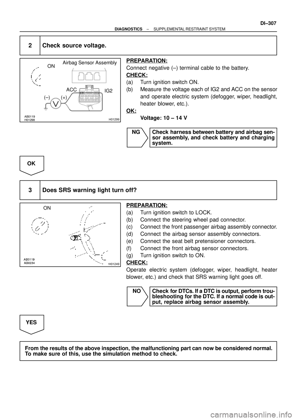
2 Check source voltage.
PREPARATION:
Connect negative (±) terminal cable to the battery.
CHECK:
(a) Turn ignition switch ON.
(b) Measure the voltage each of IG2 and ACC on the sensor
and operate electric system (defogger, wiper, headlight,
heater blower, etc.).
OK:
Voltage: 10 ± 14 V
NG Check harness between battery and airbag sen-
sor assembly, and check battery and charging
system.
OK
3 Does SRS warning light turn off?
PREPARATION:
(a) Turn ignition switch to LOCK.
(b) Connect the steering wheel pad connector.
(c) Connect the front passenger airbag assembly connector.
(d) Connect the airbag sensor assembly connectors.
(e) Connect the seat belt pretensioner connectors.
(f) Connect the front airbag sensor connectors.
(g) Turn ignition switch to ON.
CHECK:
Operate electric system (defogger, wiper, headlight, heater
blower, etc.) and check that SRS warning light goes off.
NO Check for DTCs. If a DTC is output, perform trou-
bleshooting for the DTC. If a normal code is out-
put, replace airbag sensor assembly.
YES
From the results of the above inspection, the malfunctioning part can now be considered normal.
To make sure of this, use the simulation method to check.
Page 2494 of 4592
N16045
3 4
DI±342
± DIAGNOSTICSCRUISE CONTROL SYSTEM
3 Check control switch.
PREPARATION:
(a) Remove steering wheel center pad.
(b) Disconnect the control switch connector.
CHECK:
Measure resistance between terminals 3 and 4 of control switch
connector when control switch is operated.
Switch positionResistance (W)
Neutral8 (No continuity)
RES/ACC50 ± 80
SET/COAST180 ± 220
CANCEL400 ± 440
NG Replace control switch.
OK
4Check harness and connector between cruise control ECU and cruise control switch,
cruise control switch and body ground (See page
IN±29).
NG Repair or replace harness or connector.
OK
5 Input signal check (See step 1).
OK Wait and see.
NG
Check and replace cruise control ECU
(See page IN±29).
Page 2511 of 4592
N15969
35
± DIAGNOSTICSCRUISE CONTROL SYSTEM
DI±359
2 Check main switch continuity.
PREPARATION:
(a) Remove steering wheel pad
(See Pub. No. RM654U on page SR±11).
(b) Disconnect the control switch connector.
CHECK:
Check continuity between terminals 3 and 5 of control switch
connector when main switch is held ON and OFF.
OK:
Switch positionTester connectionSpecified condition
OFF3 ± 5No continuity
Hold ON3 ± 5Continuity
NG Replace control switch.
OK
3 Check harness and connector between cruise control ECU and main switch
(See page IN±29).
NG Repair or replace harness or connector.
OK
Check and replace cruise control ECU
(See page IN±29).
Page 2814 of 4592
W02655
Marks
± INTRODUCTIONFOR ALL OF VEHICLES
IN±11
11 Author�: Date�:
(3) Even in cases of a minor collision where the SRS
does not deploy, the steering wheel pad, front pas-
senger airbag assembly, side airbag assembly and
seat belt pretensioner should be inspected (See
page RS±16, RS±29, and BO±127).
(4) Never use SRS parts from another vehicle. When
replacing parts, replace them with new parts.
(5) Before repairs, remove the airbag sensor if shocks
are likely to be applied to the sensor during repairs.
(6) Never disassemble and repair the airbag sensor as-
sembly, steering wheel pad, front passenger airbag
assembly, side airbag assembly or seat belt preten-
sioner.
(7) If the airbag sensor assembly, steering wheel pad,
front passenger airbag assembly, side airbag as-
sembly or seat belt pretensioner has been dropped,
or if there are cracks, dents or other defects in the
case, bracket or connector, replace them with new
ones.
(8) Do not directly expose the airbag sensor assembly,
steering wheel pad, front passenger airbag assem-
bly, side airbag assembly or seat belt pretensioner
to hot air or flames.
(9) Use a volt/ohmmeter with high impedance (10 kW/V
minimum) for troubleshooting of the electrical cir-
cuit.
(10) Information labels are attached to the periphery of
the SRS components. Follow the instructions on the
notices.
(11) After work on the supplemental restraint system is
completed, check the SRS warning light (See page
DI±626).
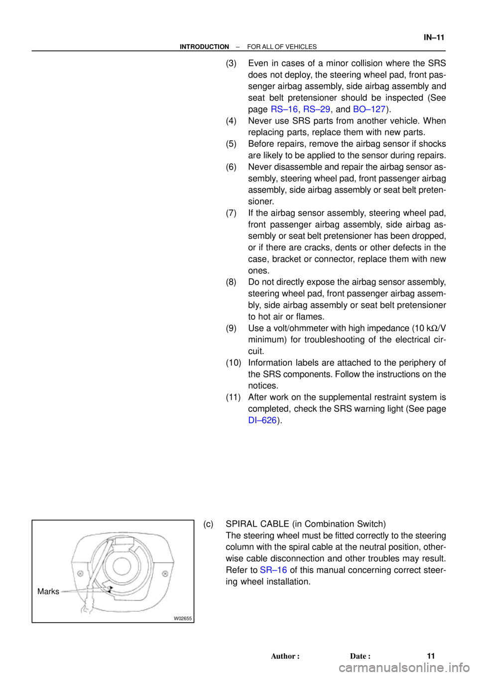
(c) SPIRAL CABLE (in Combination Switch)
The steering wheel must be fitted correctly to the steering
column with the spiral cable at the neutral position, other-
wise cable disconnection and other troubles may result.
Refer to SR±16 of this manual concerning correct steer-
ing wheel installation.
Page 2815 of 4592
Z13953
Example:CorrectWrong
Z13950
Example: IN±12
± INTRODUCTIONFOR ALL OF VEHICLES
12 Author�: Date�:
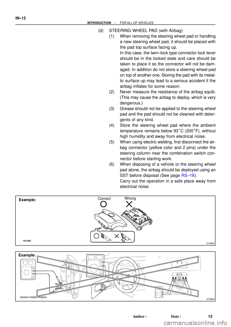
(d) STEERING WHEEL PAD (with Airbag)
(1) When removing the steering wheel pad or handling
a new steering wheel pad, it should be placed with
the pad top surface facing up.
In this case, the twin±lock type connector lock lever
should be in the locked state and care should be
taken to place it so the connector will not be dam-
aged. In addition do not store a steering wheel pad
on top of another one. Storing the pad with its metal-
lic surface up may lead to a serious accident if the
airbag inflates for some reason.
(2) Never measure the resistance of the airbag squib.
(This may cause the airbag to deploy, which is very
dangerous.)
(3) Grease should not be applied to the steering wheel
pad and the pad should not be cleaned with deter-
gents of any kind.
(4) Store the steering wheel pad where the ambient
temperature remains below 93°C (200°F), without
high humidity and away from electrical noise.
(5) When using electric welding, first disconnect the air-
bag connector (yellow color and 2 pins) under the
steering column near the combination switch con-
nector before starting work.
(6) When disposing of a vehicle or the steering wheel
pad alone, the airbag should be deployed using an
SST before disposal (See page RS±18).
Carry out the operation in a safe place away from
electrical noise.
Page 2821 of 4592
N21624
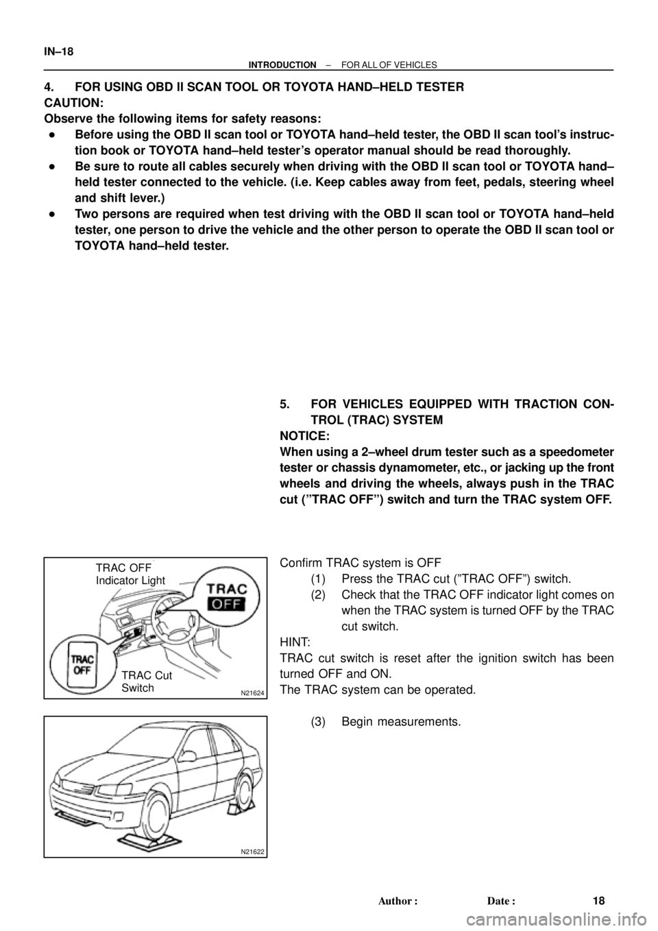
TRAC OFF
Indicator Light
TRAC Cut
Switch
N21622
IN±18
± INTRODUCTIONFOR ALL OF VEHICLES
18 Author�: Date�:
4. FOR USING OBD II SCAN TOOL OR TOYOTA HAND±HELD TESTER
CAUTION:
Observe the following items for safety reasons:
�Before using the OBD II scan tool or TOYOTA hand±held tester, the OBD II scan tool's instruc-
tion book or TOYOTA hand±held tester's operator manual should be read thoroughly.
�Be sure to route all cables securely when driving with the OBD II scan tool or TOYOTA hand±
held tester connected to the vehicle. (i.e. Keep cables away from feet, pedals, steering wheel
and shift lever.)
�Two persons are required when test driving with the OBD II scan tool or TOYOTA hand±held
tester, one person to drive the vehicle and the other person to operate the OBD II scan tool or
TOYOTA hand±held tester.
5. FOR VEHICLES EQUIPPED WITH TRACTION CON-
TROL (TRAC) SYSTEM
NOTICE:
When using a 2±wheel drum tester such as a speedometer
tester or chassis dynamometer, etc., or jacking up the front
wheels and driving the wheels, always push in the TRAC
cut (ºTRAC OFFº) switch and turn the TRAC system OFF.
Confirm TRAC system is OFF
(1) Press the TRAC cut (ºTRAC OFFº) switch.
(2) Check that the TRAC OFF indicator light comes on
when the TRAC system is turned OFF by the TRAC
cut switch.
HINT:
TRAC cut switch is reset after the ignition switch has been
turned OFF and ON.
The TRAC system can be operated.
(3) Begin measurements.