Page 2291 of 4592
Q00061
AT8562
AT3417
OK if hot
Add if hot
AT4252
0 ± 1 mm (0 ± 0.04 in.)
± DIAGNOSTICSAUTOMATIC TRANSAXLE
DI±139
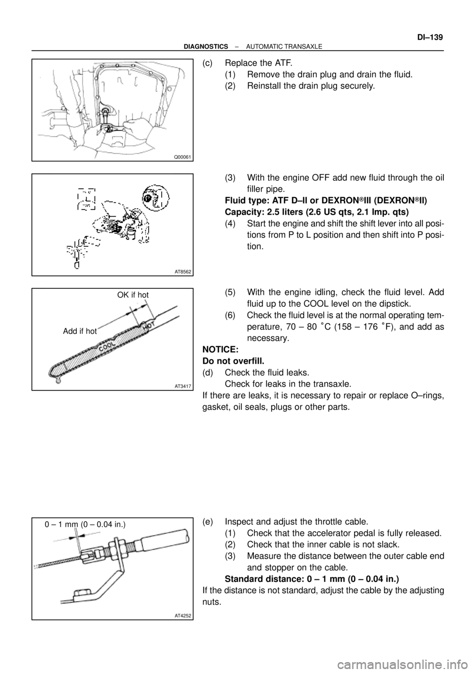
(c) Replace the ATF.
(1) Remove the drain plug and drain the fluid.
(2) Reinstall the drain plug securely.
(3) With the engine OFF add new fluid through the oil
filler pipe.
Fluid type: ATF D±II or DEXRON®III (DEXRON®II)
Capacity: 2.5 liters (2.6 US qts, 2.1 Imp. qts)
(4) Start the engine and shift the shift lever into all posi-
tions from P to L position and then shift into P posi-
tion.
(5) With the engine idling, check the fluid level. Add
fluid up to the COOL level on the dipstick.
(6) Check the fluid level is at the normal operating tem-
perature, 70 ± 80 °C (158 ± 176 °F), and add as
necessary.
NOTICE:
Do not overfill.
(d) Check the fluid leaks.
Check for leaks in the transaxle.
If there are leaks, it is necessary to repair or replace O±rings,
gasket, oil seals, plugs or other parts.
(e) Inspect and adjust the throttle cable.
(1) Check that the accelerator pedal is fully released.
(2) Check that the inner cable is not slack.
(3) Measure the distance between the outer cable end
and stopper on the cable.
Standard distance: 0 ± 1 mm (0 ± 0.04 in.)
If the distance is not standard, adjust the cable by the adjusting
nuts.
Page 2295 of 4592

± DIAGNOSTICSAUTOMATIC TRANSAXLE
DI±143
7. HYDRAULIC TEST
Measure the line pressure.
NOTICE:
�Do the test at normal operation fluid temperature 50 ± 80 °C (122 ± 176 °F).
�The line pressure test should always be carried out in pairs. One technician should observe
the conditions of wheels or wheel stoppers outside the vehicle while the other is doing the test.
�Be careful to prevent SST's hose from interfering with the exhaust pipe.
(1) Warm up the ATF.
(2) Remove the test plug on the transaxle case front left side and connect SST.
(See Pub. No. RM654U on page AX±17 for the location to connect SST)
SST 09992±00095 (09992±00231, 09992±00271)
(3) Fully apply the parking brake and chock the 4 wheels.
(4) Connect an OBD II scan tool or hand±held tester to DLC3.
(5) Start the engine and check idling speed.
(6) Keep your left foot pressing firmly on the brake pedal and shift into D position.
(7) Measure the line pressure when the engine is idling.
(8) Depress the accelerator pedal all the way down. Quickly read the highest line pressure when
engine speed reaches stall speed.
(9) In the same manner, do the test in R position.
Specified line pressure:
ConditionD position kPa (kgf/cm2, psi)R position kPa (kgf/cm2, psi)
Idling362 ± 422 (3.7 ± 4.3, 53 ± 61)618 ± 794 (6.3 ± 8.1, 90 ± 115)
Stall735 ± 862 (7.5 ± 8.8, 107 ± 125)1,373 ± 1,608 (14.0 ± 16.4, 199 ± 233)
If the measured pressure is not up to the specified value, recheck the throttle cable adjustment and retest.
Evaluation:
ProblemPossible cause
If the measured values at all positions are higher
�Throttle cable out of adjustment
�Throttle valve defective
�Regulator valve defective
If the measured values at all positions are lower
�Throttle cable out of adjustment
�Throttle valve defective
�Regulator valve defective
�Oil pump defective
�O/D direct clutch defective
If pressure is low in the D position only�D position circuit fluid leakage
�Forward clutch defective
If pressure is low in the R position only
�R position circuit fluid leakage
�Direct clutch defective
�1st & reverse brake defective
Page 2301 of 4592

± DIAGNOSTICSAUTOMATIC TRANSAXLE
DI±149
Chapter 2: On±Vehicle Repair
(�: A140E AUTOMATIC TRANSAXLE Repair Manual Pub. No. RM385U)
SymptomSuspect AreaSee page
Vehicle does not move in any forward positions and reverse posi-
tion
1. Manual valve
2. Throttle valve
3. Primary regulator valve
4. Off±vehicle repair matrix chart�
�
�
±
Vehicle does not move in R position1. Off±vehicle repair matrix chart±
No up±shift (1st " 2nd)1. 1±2 shift valve
2. Off±vehicle repair matrix chart�
±
No up±shift (2nd " 3rd)1. 2±3 shift valve
2. Off±vehicle repair matrix chart�
±
No up±shift (3rd " O/D)1. 3±4 shift valve
2. Off±vehicle repair matrix chart�
±
No down±shift (O/D " 3rd)1. 3±4 shift valve�
No down±shift (3rd " 2nd)1. 2±3 shift valve�
No down±shift (2nd " 1st)1. 1±2 shift valve�
No lock±up or No lock±up off1. Lock±up relay valve
2. Off±vehicle repair matrix chart�
±
Harsh engagement (N " D)1. C1 accumulator
2. Off±vehicle repair matrix chart�
±
Harsh engagement (N " R)1. C2 accumulator
2. Off±vehicle repair matrix chart�
±
Harsh engagement (N " L)1. Low coast modulator valve�
Harsh engagement (Lock±up)1. Lock±up relay valve
2. Off±vehicle repair matrix chart�
±
Harsh engagement (1st " 2nd " 3rd " O/D)
1. Throttle modulator valve
2. Cut back valve
3. Throttle valve�
�
�
Harsh engagement (2nd " 3rd)1. C2 accumulator�
Harsh engagement (3rd " O/D)1. B0 accumulator�
Harsh engagement (O/D " 3rd)1. C0 accumulator
2. B
0 accumulator
�
�
Slip or shudder (Forward and reverse)
1. Throttle valve
2. Oil strainer
3. Off±vehicle repair matrix chart�
�
±
No engine braking (1st: L position)1. Low coast modulator valve
2. Off±vehicle repair matrix chart�
±
No engine braking (2nd: 2 position)1. 2nd coast modulator valve
2. Off±vehicle repair matrix chart�
±
No kick±down
1. 1±2 shift valve
2. 2±3 shift valve
3. 3±4 shift valve�
�
�
Page 2340 of 4592
F00048
12 (+) (±)
Engine Room
R/B No. 3
3
45 6 12 (+) (±)
Engine Room
R/B No. 3
3
45 6 12 (+) (±)
Engine Room
R/B No. 3
3
45 612 (+) (±)
Engine Room
R/B No. 3
3
45 6
F07153
3
4
ABS
Actuator
ABS
Solenoid
Relay
A4
A13
ECUA5
1234
56781
5 2
6 3
7 4
8
SFRH
SFRR
SRLR
SRLH
SFLH
SFLR
SRRH
SRRR
DI±188
± DIAGNOSTICSANTI±LOCK BRAKE SYSTEM
INSPECTION PROCEDURE
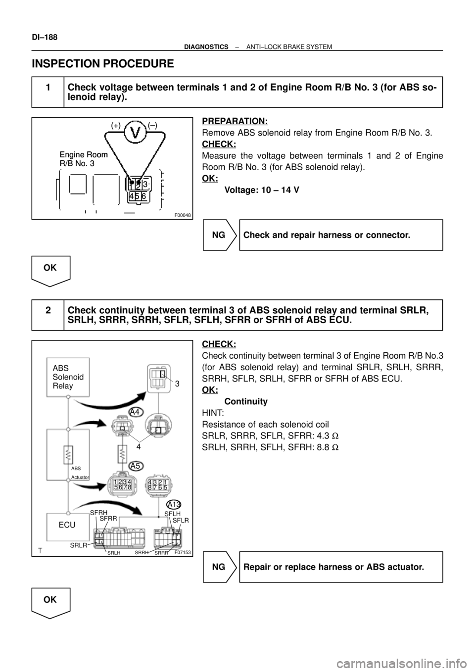
1 Check voltage between terminals 1 and 2 of Engine Room R/B No. 3 (for ABS so-
lenoid relay).
PREPARATION:
Remove ABS solenoid relay from Engine Room R/B No. 3.
CHECK:
Measure the voltage between terminals 1 and 2 of Engine
Room R/B No. 3 (for ABS solenoid relay).
OK:
Voltage: 10 ± 14 V
NG Check and repair harness or connector.
OK
2 Check continuity between terminal 3 of ABS solenoid relay and terminal SRLR,
SRLH, SRRR, SRRH, SFLR, SFLH, SFRR or SFRH of ABS ECU.
CHECK:
Check continuity between terminal 3 of Engine Room R/B No.3
(for ABS solenoid relay) and terminal SRLR, SRLH, SRRR,
SRRH, SFLR, SRLH, SFRR or SFRH of ABS ECU.
OK:
Continuity
HINT:
Resistance of each solenoid coil
SRLR, SRRR, SFLR, SFRR: 4.3 W
SRLH, SRRH, SFLH, SFRH: 8.8 W
NG Repair or replace harness or ABS actuator.
OK
Page 2554 of 4592
EM07Y±05
S05312
Compression
Gauge
± ENGINE MECHANICAL (5S±FE)COMPRESSION
EM±3
1175 Author�: Date�:
COMPRESSION
INSPECTION
HINT:
If there is lack of power, excessive oil consumption or poor fuel
economy, measure the compression pressure.
1. WARM UP AND STOP ENGINE
Allow the engine to warm up to normal operating temperature.
2. DISCONNECT IGNITION COIL CONNECTORS
3. REMOVE SPARK PLUGS (See page IG±1)
4. INSPECT CYLINDER COMPRESSION PRESSURE
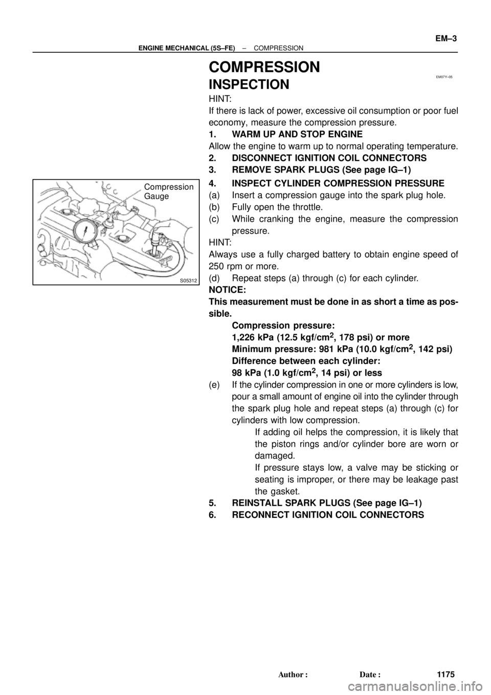
(a) Insert a compression gauge into the spark plug hole.
(b) Fully open the throttle.
(c) While cranking the engine, measure the compression
pressure.
HINT:
Always use a fully charged battery to obtain engine speed of
250 rpm or more.
(d) Repeat steps (a) through (c) for each cylinder.
NOTICE:
This measurement must be done in as short a time as pos-
sible.
Compression pressure:
1,226 kPa (12.5 kgf/cm
2, 178 psi) or more
Minimum pressure: 981 kPa (10.0 kgf/cm
2, 142 psi)
Difference between each cylinder:
98 kPa (1.0 kgf/cm
2, 14 psi) or less
(e) If the cylinder compression in one or more cylinders is low,
pour a small amount of engine oil into the cylinder through
the spark plug hole and repeat steps (a) through (c) for
cylinders with low compression.
�If adding oil helps the compression, it is likely that
the piston rings and/or cylinder bore are worn or
damaged.
�If pressure stays low, a valve may be sticking or
seating is improper, or there may be leakage past
the gasket.
5. REINSTALL SPARK PLUGS (See page IG±1)
6. RECONNECT IGNITION COIL CONNECTORS
Page 2562 of 4592
EM082±04
Z19417
TDCCrankshaft
Gear
No.1 Balance
Shaft Gear30°
AB
AB 1
2
3
4
100°
210°
280°
P06121
C C
Z19411
No.1 Balance ShaftMark B
Mark A
No.2 Housing
Z19413
No.1 Balance
Shaft
Mark B
Mark A No.2 Housing
± ENGINE MECHANICAL (5S±FE)BALANCE SHAFT BACKLASH
EM±11
1183 Author�: Date�:
BALANCE SHAFT BACKLASH
ON±VEHICLE INSPECTION
1. REMOVE OIL PAN AND OIL STRAINER
(See page LU±7)
2. INSPECT BACKLASH OF CRANKSHAFT GEAR AND
NO.1 BALANCE SHAFT GEAR
NOTICE:
Backlash between the crankshaft gear and No.1 balance
shaft gear varies with the rotation of the balance shaft and
the deviation of the crankshaft gear. Accordingly, it is nec-
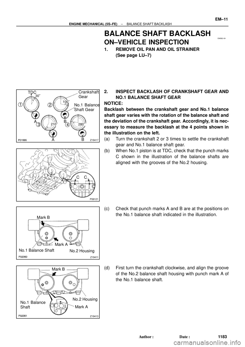
essary to measure the backlash at the 4 points shown in
the illustration on the left.
(a) Turn the crankshaft 2 or 3 times to settle the crankshaft
gear and No.1 balance shaft gear.
(b) When No.1 piston is at TDC, check that the punch marks
C shown in the illustration of the balance shafts are
aligned with the grooves of the No.2 housing.
(c) Check that punch marks A and B are at the positions on
the No.1 balance shaft indicated in the illustration.
(d) First turn the crankshaft clockwise, and align the groove
of the No.2 balance shaft housing with punch mark A of
the No.1 balance shaft.
Page 2564 of 4592
Z19415
No.1 Balance
Shaft
Mark B
Mark A
No.2 Housing
Z19408
2
46 153
Z19409
1
35 Pull
264
± ENGINE MECHANICAL (5S±FE)BALANCE SHAFT BACKLASH
EM±13
1185 Author�: Date�:
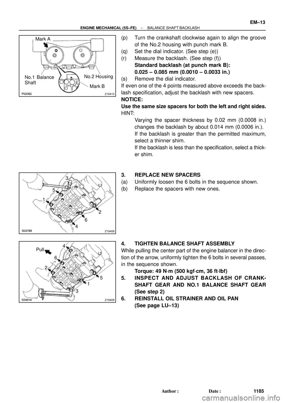
(p) Turn the crankshaft clockwise again to align the groove
of the No.2 housing with punch mark B.
(q) Set the dial indicator. (See step (e))
(r) Measure the backlash. (See step (f))
Standard backlash (at punch mark B):
0.025 ± 0.085 mm (0.0010 ± 0.0033 in.)
(s) Remove the dial indicator.
If even one of the 4 points measured above exceeds the back-
lash specification, adjust the backlash with new spacers.
NOTICE:
Use the same size spacers for both the left and right sides.
HINT:
�Varying the spacer thickness by 0.02 mm (0.0008 in.)
changes the backlash by about 0.014 mm (0.0006 in.).
�If the backlash is greater than the permitted maximum,
select a thinner shim.
�If the backlash is less than the specification, select a thick-
er shim.
3. REPLACE NEW SPACERS
(a) Uniformly loosen the 6 bolts in the sequence shown.
(b) Replace the spacers with new ones.
4. TIGHTEN BALANCE SHAFT ASSEMBLY
While pulling the center part of the engine balancer in the direc-
tion of the arrow, uniformly tighten the 6 bolts in several passes,
in the sequence shown.
Torque: 49 N´m (500 kgf´cm, 36 ft´lbf)
5. INSPECT AND ADJUST BACKLASH OF CRANK-
SHAFT GEAR AND NO.1 BALANCE SHAFT GEAR
(See step 2)
6. REINSTALL OIL STRAINER AND OIL PAN
(See page LU±13)
Page 2567 of 4592
S05937
No.2 Timing Belt
Cover
No.1 Timing Belt
Cover
Tension Spring Crankshaft
Pulley
Camshaft Timing Pulley
No.1 Idler Pulley
No.2 Idler Pulley
Oil Pump Pulley
Crankshaft Timing Pulley Wire ClampWire ClampWire ClampSpark Plug High±Tension CordTiming Belt Guide Timing Belt
*
1 Gasket Wire
ClampGenerator Wire
Generator Connector
Generator
Wire
Clamp
N´m (kgf´cm, ft´lbf)
*
2 For use with SST
42 (425, 31)
42 (425, 31)
24 (245, 18)18 (180, 13) 108 (1,100, 80)
54 (550, 40)
*
2
37 (380, 27)
: Specified torque*
1 Gasket
*
1
Replace only if damaged EM±16
± ENGINE MECHANICAL (5S±FE)TIMING BELT
1188 Author�: Date�: