Page 2149 of 4592
I08435
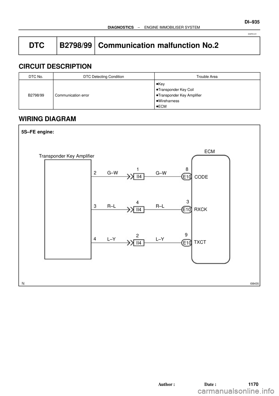
ECM
E10 28
93
E10
E10 3
4G±W
R±L
L±Y Transponder Key Amplifier
CODE
RXCK
TXCT 5S±FE engine:
G±W
R±L
L±Y 1
II4
4
II4
2
II4
± DIAGNOSTICSENGINE IMMOBILISER SYSTEM
DI±935
1170 Author�: Date�:
DTC B2798/99 Communication malfunction No.2
CIRCUIT DESCRIPTION
DTC No.DTC Detecting ConditionTrouble Area
B2798/99Communication error
�Key
�Transponder Key Coil
�Transponder Key Amplifier
�Wireharness
�ECM
WIRING DIAGRAM
DI4FH±01
Page 2151 of 4592
± DIAGNOSTICSENGINE IMMOBILISER SYSTEM
DI±937
1172 Author�: Date�:
INSPECTION PROCEDURE
1 Check transponder key coil (See page BE±128).
NG Replace transponder key coil
OK
2 Check harness and connector between transponder key amplifier and ECM.
NG Repair or replace harness and connector
OK
3 Does it operate normally after replacement of transponder key amplifier?
Yes Replace transponder key amplifier.
No
Replace ECM.
Page 2160 of 4592
P00495
Outside
Inside
± DIAGNOSTICSENGINE
DI±9
4 Check air filter.
PREPARATION:
Remove the air filter.
CHECK:
Visually check that the air filter is not dirty or excessive oily.
HINT:
If necessary, clean the air filter with compressed air. First blow
from inside thoroughly, then blow from outside of the air filter.
NG Repair or replace.
OK
5 Check idle speed.
PREPARATION:
(a) Warm up the engine to normal operating temperature.
(b) Switch off all the accessories.
(c) Switch off the A/C.
(d) Shift the transmission into the N position.
(e) Connect the OBD II scan tool or TOYOTA hand±held tester to the DLC3 on the vehicle.
CHECK:
Use the CURRENT DATA to check the idle speed.
OK:
Idle speed: 650 ± 750 rpm
NG Proceed to problem symptoms table on page
DI±21.
OK
Page 2163 of 4592

DI±12
± DIAGNOSTICSENGINE
SHORT FT #1
Short±term Fuel Trim Bank 10 ± 20 %
LONG FT #1Long±term Fuel Trim Bank 10 ± 20 %
ENGINE SPDEngine SpeedIdling: 650 ± 750 rpm
VEHICLE SPDVehicle SpeedVehicle Stopped: 0 km/h (0 mph)
IGN ADVANCEIgnition Advance: Ignition Timing of Cylinder No.1Idling: BTDC 0 ± 10°
INTAKE AIRIntake Air Temp. Sensor ValueEquivalent to Ambient Temp.
MAPAbsolute Pressure inside Intake ManifoldIdling: 20 ± 51 kPa
Racing without load (2,500 rpm): 17 ± 48 kPa
THROTTLE POSVoltage Output of Throttle Position Sensor Calcu-
lated as a percentage: 0 V "0 %, 5 V "100 %Throttle Fully Closed: 6 ± 16 %
Throttle Fully Open: 64 ± 98 %
O2S B1 S1Voltage Output of Heated Oxygen Sensor Bank 1
Sensor 1Idling: 0.1 ± 0.9 V (0.56 ± 0.76 V*2)
O2FT B1 S1Heated Oxygen Sensor Fuel Trim Bank 1 Sensor
1 (Same as SHORT FT #1)0 ± 20 %
A/FS B1 S1Voltage Output of A/F SensorIdling: 2.8 ± 3.8 V
A/FFT B1 S1A/F Sensor Fuel Trim (Same as SHORT FT #1)0 ± 20 %
O2S B1 S2Voltage Output of Heated Oxygen Sensor Bank 1
Sensor 2Driving at 50 km/h (31 mph): 0.05 ± 0.95 V
*1: If no conditions are specifically stated for ºldlingº, it means the shift lever is at N or P position, the A/C
switch is OFF and all accessory switches are OFF.
*
2: When you use the OBD II scan tool (excluding TOYOTA hand±held tester).
(b) TOYOTA Enhanced Signals.
TOYOTA hand±held tester displayMeasurement ItemNormal Condition*
MISFIRE RPMEngine RPM for first misfire rangeMisfire 0: 0 rpm
MISFIRE LOADEngine load for first misfire rangeMisfire 0: 0 g/r
INJECTORFuel injection time for cylinder No.1Idling: 2.9 ± 5.1 ms
IAC DUTY RATIOIntake Air Control Valve Duty Ratio
Opening ratio rotary solenoid type IAC valveIdling: 25 ± 62 %
STARTER SIGStarter SignalCranking: ON
CTP SIGClosed Throttle Position SignalThrottle fully closed: ON
A/C SIGA/C Switch SignalA/C ON: ON
PNP SIGPark/Neutral Position Switch SignalP or N position: ON
ELECTCL LOAD SIGElectrical Load SignalDefogger S/W ON: ON
STOP LIGHT SWStop Light Switch SignalStop light switch ON: ON
PS OIL PRESS SWPower Steering Oil Pressure Switch SignalTurn steering wheel: ON
FC IDLFuel Cut Idle: Fuel cut when throttle valve fully
closed, during decelerationFuel cut operating: ON
FC TAUFuel Cut TAU: Fuel cut during very light loadFuel cut operating: ON
CYL#1, CYL#2, CYL#3, CYL#4Abnormal revolution variation for each cylinder0 %
IGNITIONTotal number of ignition for every 1,000 revolu-
tions0 ± 2,000
EGR SYSTEMEGR system operating conditionIdling: OFF
FUEL PUMPFuel Pump SignalIdling: ON
A/C CUT SIGA/C Cut SignalA/C S/W OFF: ON
A/C MAG CLUTCHA/C Switch SignalA/C ON: ON
EVAP (PURGE) VSVEVAP VSV SignalVSV operating: Avove 30 %
Page 2167 of 4592

Fuel Pressure Regulator Mal-
function
�Open or short in fuel shutoff valve circuit for fuel tank
�Fuel shutoff valve for fuel tank
�Open or short in fuel shu")
DI±16
± DIAGNOSTICSENGINE
P1190
(DI±86)
Fuel Pressure Regulator Mal-
function
�Open or short in fuel shutoff valve circuit for fuel tank
�Fuel shutoff valve for fuel tank
�Open or short in fuel shutoff valve circuit for fuel pressure reg-
ulator
�Fuel shutoff valve for fuel pressure regulator
�Fuel pressure regulator
�Open or short in fuel shutoff valve circuit for fuel delivery pipe
�Fuel shutoff valve for fuel delivery pipe
�ECM
��
P1240
(DI±95)Fuel Fuel Shutoff Valve Circuit
for Delivery Pipe Malfunction�Open or short in fuel shutoff valve circuit for fuel delivery pipe
�Fuel shutoff valve for fuel delivery pipe
�ECM
±�
P1245
(DI±98)Fuel Fuel Shutoff Valve Circuit
for Pressure Regulator Malfunc-
tion�Open or short in fuel shutoff valve circuit for fuel pressure reg-
ulator
�Fuel shutoff valve for fuel pressure regulator
�ECM
±�
P1300
(DI±102)Igniter Circuit Malfunction (No.1)
�Ignition system
�Open or short in IGF or IGT1 circuit from No.1 ignition coil with
igniter to ECM
�No.1 ignition coil with igniter
�ECM
��
P1310
(DI±102)Igniter Circuit Malfunction (No.2)
�Ignition system
�Open or short in IGF or IGT2 circuit from No.2 ignition coil with
igniter to ECM
�No.2 ignition coil with igniter
�ECM
��
P1335
(DI±107)Crankshaft Position Sensor Cir-
cuit Malfunction (During engine
running)�Open short in crankshaft position sensor circuit
�Crankshaft position sensor
�Crankshaft timing pulley
�ECM
±�
P1520
(DI±108)Stop Light Switch Signal Mal-
function�Short in stop light switch signal circuit
�Stop light switch
�ECM
��
P1600
(DI±110)ECM BATT Malfunction�Open in back up power source circuit
�ECM��
P1780
(DI±112)Park/Neutral Position Switch
Malfunction�Short in park/neutral position switch circuit
�Park/neutral position switch
�ECM
��
*: � ... MIL lights up. ± ... MIL does not light up.
Page 2168 of 4592
DI1JS±04
A09176
Crankshaft Position
SensorVSV for EGR DLC1
Camshaft Position
Sensor InjectorECMThrottle Position SensorManifold Absolute
Pressure Sensor
Combination Meter
for Speedometer
DLC3
Heated Oxygen
Sensor (Bank 1
Sensor 2)
Intake Air Temperature
Sensor
Idle Air Control
Valve
Ignition Coil (No.1, No.2) Park/Neutral
Position Switch Engine Coolant
Temperature
Sensor A/F Sensor
Bank 1
Sensor 1)
Fuel Pressure
Sensor for
Delivery Pipe
Fuel Pressure Regulator
Fuel Temperature
Sensor for Fuel
Tank
Fuel Temperature
Sensor for
Delivery Pipe
Fuel Shutoff Valve for
Pressure Regulator
Fuel Pressure Sensor
for Fuel Pipe
Fuel Shutoff Valve
for Fuel Tank
± DIAGNOSTICSENGINE
DI±17
PARTS LOCATION
Page 2169 of 4592

DI64T±01
A02958
E4ECM Terminals
E6E5E7
11
19
1412 10 9 8
7652
43
18 21 22
20
16151
13
17 11 14
109
87 652 4
3
21 2220
16 15 131
12 11 1 09
652
43 1 12
7 8
19
14
109 8
7652
43
18
23 2416
151
17
11 12 13 25
26 DI±18
± DIAGNOSTICSENGINE
TERMINALS OF ECM
Symbols (Terminals No.)Wiring ColorConditionSTD Voltage (V)
BATT (E4±1) ± E1 (E6±16)B±Y e BRAlways9 ± 14
+B (E4±12) ± E1 (E6±16)B±Y e BRIG switch ON9 ± 14
VC (E5±1) ± E2 (E5±9)Ye BRIG switch ON4.5 ± 5.5
PIM (E5 2) E2 (E5 9)BYBR
IG switch ON3.3 ± 3.9
PIM (E5±2) ± E2 (E5±9)B±Y e BRApply vacuum 26.7 kPa (200 mmHg, 7.9 in.Hg)2.5 ± 3.1
THA (E5±3) ± E2 (E5±9)Y±B e BRIdling, Intake air temp. 20°C (68° F)0.5 ± 3.4
THW (E5±4) ± E2 (E5±9)G±B e BRIdling, Engine coolant temp. 80°C (176°F)0.2 ± 1.0
VTA (E5 11) E2 (E5 9)LGBRIG switch ON, Throttle valve fully closed0.3 ± 1.0VTA (E5±11) ± E2 (E5±9)LG e BRIG switch ON, Throttle valve fully open3.2 ± 4.9
AF+ (E5±6) ± E1 (E6±16)L e BRAlways (IG switch ON)3.3 fixed*
AF± (E5±14) ± E1 (E6±16)B±W e BRAlways (IG switch ON)3.0 fixed*
HT2 (E6 21) E1 (E6 16)PBBRIdlingBelow 3.0HT2 (E6±21) ± E1 (E6±16)P±B e BRIG switch ON9 ± 14
THCNG2 (E7±6) ± E2 (E5±9)P±B e BR
IG switch ON, Fuel temperature ±20°C (4° F)
20°C (68° F)
80°C (176° F)0.66 ± 0.78
2.5 ± 2.75
4.42 ± 4.52
PCNG2 (E7±5) ± E2 (E5±9)G±B e BRIdling ON, Fuel temperature 20°C (68° F)3.1 ± 3.6
STA (E4 11) E1 (E6 16)GRBRCki60STA (E4±11) ± E1 (E6±16)GR e BRCranking6.0 or more
IGT1 (E6±20) ± E1 (E6±16)B e BRIdlingPulse generation
(See page DI±102)
IGT2 (E6±19) ± E1 (E6±16)Y±R e BRIdlingPulse generation
(See page DI±102)
IG switch ON, Disconnect ignition coil connector4.5 ± 5.5
IGF (E6±3) ± E1 (E6±16)W±R e BRIdlingPulse generation
(See page DI±102)
G (E6±5) ± NE± (E6±17)B±W e LIdlingPulse generation
(See page DI±59)
NE (E6±4) ± NE± (E6±17)B±R e LIdlingPulse generation
(See page DI±59)
EGR (E6±23) ± E01(E6±13)P±B e BRIG switch ON0 ± 3
OX2 (E5±5) ± E1 (E6±16)B e BRMaintain engine speed at 2,500 rpm for 2 min. after warming upPulse generation
RSD (E6±10) ± E1 (E6±16)W e BRIG switch ON9 ~ 14
FC (E4±14) ± E01 (E6±13)G±R e BRIG switch ON9 ± 14
Page 2210 of 4592

A09394
ECM
G
NE+
NE±
E1 E6
E6
E65
4
17 B±W
L
B±R
L BR Camshaft Position Sensor
Crankshaft Position Sensor1
2
1
2B±R
± DIAGNOSTICSENGINE
DI±59
DTC P0335 Crankshaft Position Sensor ºAº Circuit Mal-
function
CIRCUIT DESCRIPTION
Crankshaft position sensor (NE signal) consists of a magnet, iron and pickup coil.
The NE signal plate has 34 teeth and is installed on the crankshaft timing pulley. The NE signal sensor gener-
ates 34 signals at every engine revolution. The ECM detects the standard crankshaft angle based on the
G signal, and the actual crankshaft angle and the engine speed by the NE signal.
DTC No.DTC Detecting ConditionTrouble Area
P0335
No crankshaft position sensor signal to ECM during cranking
(2 trip detection logic)�Open or short in crankshaft position sensor circuit
�Crankshaft position sensor
P0335No crankshaft position sensor signal to ECM with engine
speed 600 rpm or more (2 trip detection logic)
�Crankshaft osition sensor
�Crankshaft timing pulley
�ECM
WIRING DIAGRAM
INSPECTION PROCEDURE
HINT:
�Perform troubleshooting of DTC 335 first. If no trouble is found, troubleshoot the following mechanical
system.
�Read freeze frame data using TOYOTA hand±held tester or OBD II scan tool. Because freeze frame
records the engine conditions when the malfunction is detected. When troubleshooting it is useful for
determining whether the vehicle was running or stopped, the engine was warmed up or not, the air±fuel
ratio was lean or rich, etc. at the time of the malfunction.
DI013±12