Page 2325 of 4592
D05151BE3840D06388
ON
OD2
± DIAGNOSTICSAUTOMATIC TRANSAXLE
DI±173
3 Check OVERDRIVE CUT SW2 signal.
When using hand±held tester:
PREPARATION:
(a) Remove the DLC3 cover.
(b) Connect hand±held tester to the DLC3.
(c) Turn the ignition switch to ON and hand±held tester main
switch ON.
CHECK:
Read the OVRDRIVE CUT SW2 signal on the hand±held tester.
OK:
O/D main switch conditionOVRDRIVE CUT SW2 signal
O/D ON (Pushed in)OFF
O/D OFF (Pushed once again)ON
When not using hand±held tester:
PREPARATION:
Turn the ignition switch to ON.
CHECK:
Check voltage between terminal OD2 of ECM and body ground.
OK:
O/D main switch conditionVoltage
O/D ON (Pushed in)9 ± 14
O/D OFF (Pushed once again)Below 1.5 V
OK Check and replace the ECM (See page IN±29).
NG
4 Check harness and connector between O/D OFF indicator light and ECM (See
page IN±29).
NG Repair or replace the harness or connector.
OK
Check and replace the ECM (See page
IN±29).
Page 2331 of 4592

F02201
DLC1
TsTc E1
BR3904
0.13 sec. 0.13 sec.
ON
OFF
BR3893
Malfunction Code (Example Code 72, 76)
72 67
ON
OFF
0.5 sec. 0.5 sec. 0.5 sec. 0.5 sec.1.5 sec.
2.5 sec.4 sec.
Repeat
± DIAGNOSTICSANTI±LOCK BRAKE SYSTEM
DI±179
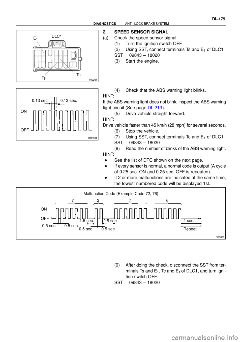
2. SPEED SENSOR SIGNAL
(a) Check the speed sensor signal.
(1) Turn the ignition switch OFF.
(2) Using SST, connect terminals Ts and E
1 of DLC1.
SST 09843 ± 18020
(3) Start the engine.
(4) Check that the ABS warning light blinks.
HINT:
If the ABS warning light does not blink, inspect the ABS warning
light circuit (See page DI±213).
(5) Drive vehicle straight forward.
HINT:
Drive vehicle faster than 45 km/h (28 mph) for several seconds.
(6) Stop the vehicle.
(7) Using SST, connect terminals Tc and E
1 of DLC1.
SST 09843 ± 18020
(8) Read the number of blinks of the ABS warning light.
HINT:
�See the list of DTC shown on the next page.
�If every sensor is normal, a normal code is output (A cycle
of 0.25 sec. ON and 0.25 sec. OFF is repeated).
�If 2 or more malfunctions are indicated at the same time,
the lowest numbered code will be displayed 1st.
(9) After doing the check, disconnect the SST from ter-
minals Ts and E
1, Tc and E1 of DLC1, and turn igni-
tion switch OFF.
SST 09843 ± 18020
Page 2333 of 4592

DI03D±04
± DIAGNOSTICSANTI±LOCK BRAKE SYSTEM
DI±181
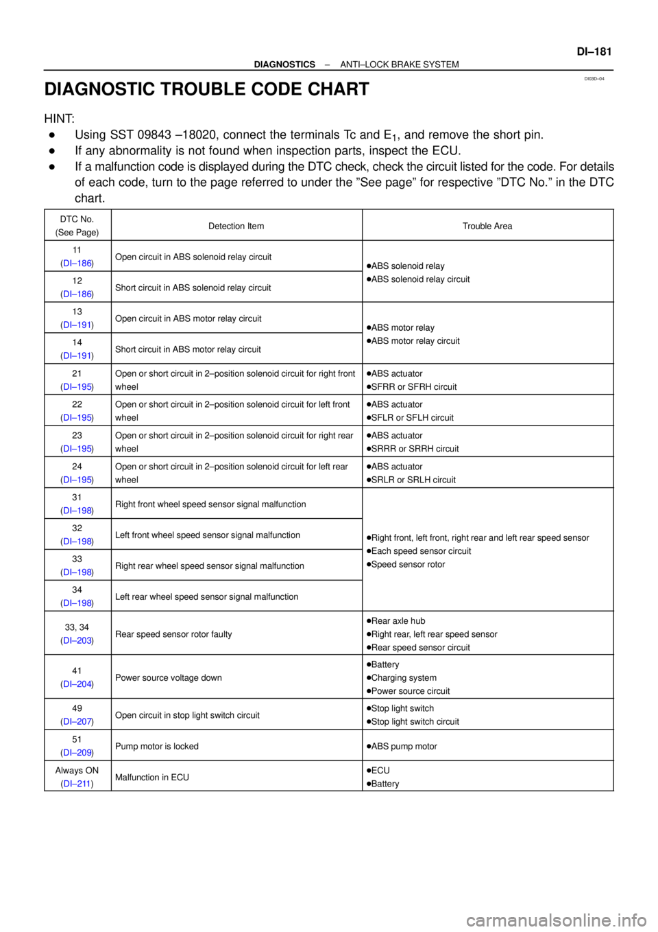
DIAGNOSTIC TROUBLE CODE CHART
HINT:
�Using SST 09843 ±18020, connect the terminals Tc and E1, and remove the short pin.
�If any abnormality is not found when inspection parts, inspect the ECU.
�If a malfunction code is displayed during the DTC check, check the circuit listed for the code. For details
of each code, turn to the page referred to under the ºSee pageº for respective ºDTC No.º in the DTC
chart.
DTC No.
(See Page)Detection ItemTrouble Area
11
(DI±186)Open circuit in ABS solenoid relay circuit�ABS solenoid relay
12
(DI±186)Short circuit in ABS solenoid relay circuit
�ABS solenoid relay
�ABS solenoid relay circuit
13
(DI±191)Open circuit in ABS motor relay circuit�ABS motor relay
14
(DI±191)Short circuit in ABS motor relay circuit
�ABS motor relay
�ABS motor relay circuit
21
(DI±195)Open or short circuit in 2±position solenoid circuit for right front
wheel�ABS actuator
�SFRR or SFRH circuit
22
(DI±195)Open or short circuit in 2±position solenoid circuit for left front
wheel�ABS actuator
�SFLR or SFLH circuit
23
(DI±195)Open or short circuit in 2±position solenoid circuit for right rear
wheel�ABS actuator
�SRRR or SRRH circuit
24
(DI±195)Open or short circuit in 2±position solenoid circuit for left rear
wheel�ABS actuator
�SRLR or SRLH circuit
31
(DI±198)Right front wheel speed sensor signal malfunction
32
(DI±198)Left front wheel speed sensor signal malfunction�Right front, left front, right rear and left rear speed sensor
Eh d i it33
(DI±198)Right rear wheel speed sensor signal malfunction
�Each speed sensor circuit
�Speed sensor rotor
34
(DI±198)Left rear wheel speed sensor signal malfunction
33, 34
(DI±203)Rear speed sensor rotor faulty
�Rear axle hub
�Right rear, left rear speed sensor
�Rear speed sensor circuit
41
(DI±204)Power source voltage down
�Battery
�Charging system
�Power source circuit
49
(DI±207)Open circuit in stop light switch circuit�Stop light switch
�Stop light switch circuit
51
(DI±209)Pump motor is locked�ABS pump motor
Always ON
(DI±211)Malfunction in ECU�ECU
�Battery
Page 2370 of 4592
F00172
EC BRA
ABR
3
16 DLC1
Ts E
1
R±Y8
R±Y8
TsABS ECU
J20
J/C
BRA
ABR
3
16 DLC1
Ts E
1
R±Y
IG38
R±Y
A148
TsABS ECU
AB0119S08096
F00446DLC1 DLC1
DLC1
DLC1DLC1
Ts
DLC1 E1
ON
DI±218
± DIAGNOSTICSANTI±LOCK BRAKE SYSTEM
Ts Terminal Circuit
CIRCUIT DESCRIPTION
The sensor check circuit detects abnormalities in the speed sensor signal which cannot be detected with
the DTC check.
Connecting terminals Ts and E
1 of the DLC1 in the engine compartment starts the check.
WIRING DIAGRAM
INSPECTION PROCEDURE
1 Check voltage between terminals Ts and E1 of DLC1.
CHECK:
(a) Turn the ignition switch ON.
(b) Measure voltage between terminals Ts and E
1 of DLC1.
OK:
Voltage: 10 ± 14 V
OK If ABS warning light does not blink even after Ts
and E
1 are connected, the ECU may be defec-
tive.
NG
DI03S±04
Page 2442 of 4592

AB0119H01298H01299
(±) (+)ONAirbag Sensor Assembly
ACC
IG2
DI±290
± DIAGNOSTICSSUPPLEMENTAL RESTRAINT SYSTEM
DTC B1100/31 Airbag Sensor Assembly Malfunction
CIRCUIT DESCRIPTION
The airbag sensor assembly consists of a airbag sensor, safing sensor, drive circuit, diagnosis circuit and
ignition control, etc.
It receives signals from the airbag sensor, judges whether or not the SRS must be activated, and detects
diagnosis system malfunction.
DTC B1100/31 is recorded when occurrence of a malfunction in the airbag sensor assembly is detected.
DTC No.DTC Detecting ConditionTrouble Area
B1100/31�Airbag sensor assembly malfunction�Airbag sensor assembly
INSPECTION PROCEDURE
HINT:
When a malfunction code other than code B1100/31 is displayed at the same time, first repair the malfunction
indicated by the malfunction code other than code B1100/31.
1 Prepare for inspection. (See step 1 on page DI±305)
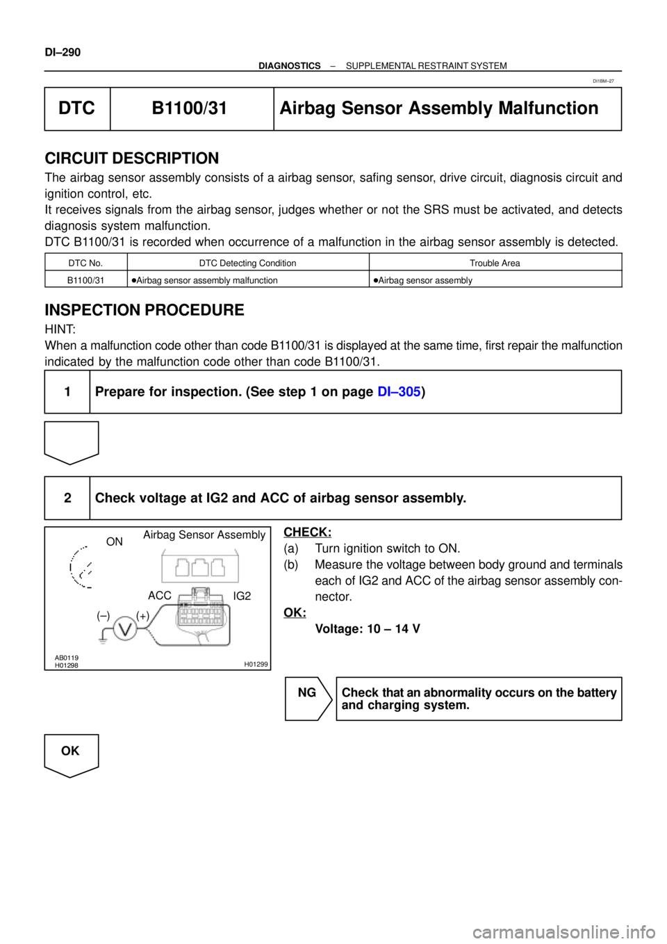
2 Check voltage at IG2 and ACC of airbag sensor assembly.
CHECK:
(a) Turn ignition switch to ON.
(b) Measure the voltage between body ground and terminals
each of IG2 and ACC of the airbag sensor assembly con-
nector.
OK:
Voltage: 10 ± 14 V
NG Check that an abnormality occurs on the battery
and charging system.
OK
DI1BM±27
Page 2475 of 4592

N17520
(1)
(2)
(1)
No.Operation MethodCRUISE MAIN Indicator Light
Blinking PatternDiagnosis
1 Turn SET/COAST switch ON
2Turn RES/ACC switch ON
3Turn CANCEL switch ON
Turn stop light switch ON
Depress brake pedal
Turn PNP switch OFF
(Shift to except D position)
4Drive at about 40 km/h
(25 mph)or higher
Drive at about 40 km/h
(25 mph) or below
LightON
OFF
LightON
OFF
LightON
OFFSwitch ON
Switch OFF
LightON
OFFSwitch OFF
Switch ONSET/COAST switch circuit
is normal
RES/ACC switch circuit
is normal
CANCEL switch circuit
is normal
Stop light switch circuit
is normal
PNP switch circuit is
normal
Vehicle Speed Sensor is
normal
LightON
OFF LightON
OFF
1sec.
0.25 sec.0.25 sec.
± DIAGNOSTICSCRUISE CONTROL SYSTEM
DI±323
5. INPUT SIGNAL CHECK
HINT:
(1): For check No.1 ± No.3
�Turn ignition switch ON.
(2): For check No.4
�Jack up the vehicle.
�Start the engine.
�Shift to D position.
(a) Pull the control switch to SET/COAST or RES/ACC posi-
tion and hold it down or up (1).
(b) Push the main switch ON (2).
(c) Check that the CRUISE MAIN indicator light blinks twice
or 3 times repeatedly after 3 seconds.
(d) Turn the SET/COAST or RES/ACC switch OFF.
(e) Operate each switch as listed in the table below.
(f) Read the blinking pattern of the CRUISE MAIN indicator
light.
(g) After performing the check, turn the main switch OFF.
HINT:
When 2 or more signals are input to the ECU, the lowest num-
bered code will be displayed first.
Page 2483 of 4592

I00281
Cruise Control ECU
C16
G±B
2 1 34W±B
3
STOP Fuse8 Stop Light Switch
4
R±Y
Stop Lights Cruise Control Actuator
� Actuator Magnetic Clutch
J6
J6AAJ/C
W±B
1J
1J
W±B
A
J/C
IF 8
7
J9Instrument
Panel J/BL
± DIAGNOSTICSCRUISE CONTROL SYSTEM
DI±331
DTC 12 Actuator Magnetic Clutch Circuit
CIRCUIT DESCRIPTION
This circuit turns on the magnetic clutch inside the actuator during cruise control operation according to the
signal from the ECU. If a malfunction occurs in the actuator or speed sensor, etc. during cruise control opera-
tion, the rotor shaft between the motor and control plate is released.
When the brake pedal is depressed, the stop light switch turns on, supplying electrical power to the stop light.
Power supply to the magnetic clutch is mechanically cut and the magnetic clutch is turned OFF.
When driving downhill, if the vehicle speed exceeds the set speed by 15 km/h (9 mph), the ECU turns the
safety magnet clutch OFF. If the vehicle speed later drops to within 10 km/h (6 mph), cruise control at the
set speed is resumed.
DTC No.DTC Detecting ConditionTrouble Area
12Short in actuator magnetic clutch circuit.
Open (0.8 sec.) in actuator magnetic clutch circuit.
�STOP Fuse
�Stop light switch
�Actuator magnetic clutch
�Harness or connector between cruise control ECU and
actuator magnetic clutch, actuator magnetic clutch and body
ground
�Cruise control ECU
WIRING DIAGRAM
DI08N±13
Page 2486 of 4592
I00055
4
3(+)
(±)
DI±334
± DIAGNOSTICSCRUISE CONTROL SYSTEM
DTC 14 Actuator Mechanical Malfunction
CIRCUIT DESCRIPTION
The circuit detects the rotation position of the actuator control plate and sends a signal to the ECU.
DTC No.DTC Detecting ConditionTrouble Area
14Cruise control actuator mechanical malfunction.
�Actuator lock: (motor, arm)
�Actuator motor
�Cruise control ECU
WIRING DIAGRAM
See page DI±329.
INSPECTION PROCEDURE
1 Check cruise control actuator arm locking operation
PREPARATION:
(a) Turn ignition switch OFF.
(b) Disconnect the actuator connector.
CHECK:
Connect the positive (+) lead from the battery to the terminal 3
of actuator and the negative (±) lead to terminal 4.
NOTICE:
Do not connect the high tension cables to the wrong bat-
tery terminal. The cruise control actuator will be damaged.
Move the control plate by hand.
OK:
Control plate doesn't move.
NG Replace cruise control actuator.
OK
DI08O±13