Page 2259 of 4592

A09400
ECM
STP 4
E4
G±W G±WJ23 J24 1R 1R
1SJ27 J/C
AC Instrument Panel J/B
5
2 4
7
12
G±WLight
Failure
Sensor
Stop
Light
(LH) Stop
Light
(RH) G±R
2
52
5
W±B
W±B
BM High
Mount
Stop
Light
2
1R
A
A
J34
J/C
BL
1
W±B
Stop Light
Switch
2
BatteryW±B W
1C 7
STOP
41BInstrument
Panel J/B
B±R
B±R
F14
2 F14
1
ALT
F9MAIN
FL
FL Block
G±W
1
B±G
DI±108
± DIAGNOSTICSENGINE
DTC P1520 Stop Light Switch Signal Malfunction
CIRCUIT DESCRIPTION
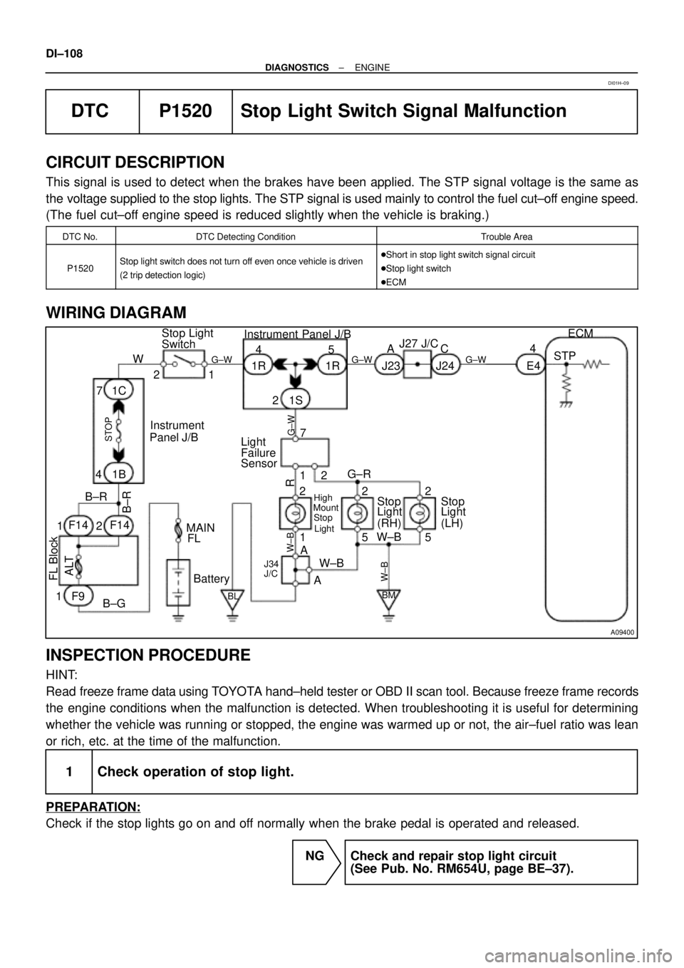
This signal is used to detect when the brakes have been applied. The STP signal voltage is the same as
the voltage supplied to the stop lights. The STP signal is used mainly to control the fuel cut±off engine speed.
(The fuel cut±off engine speed is reduced slightly when the vehicle is braking.)
DTC No.DTC Detecting ConditionTrouble Area
P1520Stop light switch does not turn off even once vehicle is driven
(2 trip detection logic)�Short in stop light switch signal circuit
�Stop light switch
�ECM
WIRING DIAGRAM
INSPECTION PROCEDURE
HINT:
Read freeze frame data using TOYOTA hand±held tester or OBD II scan tool. Because freeze frame records
the engine conditions when the malfunction is detected. When troubleshooting it is useful for determining
whether the vehicle was running or stopped, the engine was warmed up or not, the air±fuel ratio was lean
or rich, etc. at the time of the malfunction.
1 Check operation of stop light.
PREPARATION:
Check if the stop lights go on and off normally when the brake pedal is operated and released.
NG Check and repair stop light circuit
(See Pub. No. RM654U, page BE±37).
DI01H±09
Page 2260 of 4592
A09282
BE6653Q06993A09270
Brake Pedal
Depressed ON
Brake Pedal
Released
STP
(±) (+)
± DIAGNOSTICSENGINE
DI±109
OK
2 Check STP signal.
When using TOYOTA hand±held tester:
PREPARATION:
(a) Connect the TOYOTA hand±held tester to the DLC3.
(b) Turn the ignition switch ON and push the TOYOTA hand±
held tester main switch ON.
CHECK:
Read the STP signal on the TOYOTA hand±held tester.
OK:
Brake PedalSTP Signal
DepressedON
ReleasedOFF
When not using TOYOTA hand±held tester:
PREPARATION:
Turn the ignition switch ON.
CHECK:
Check the voltage between terminal STP of the ECM connector
and body ground.
OK:
Brake PedalVoltage
Depressed7.5 ± 14 V
ReleasedBelow 1.5 V
OK Check for intermittent problems
(See page DI±3).
NG
3 Check harness and connector between ECM and stop light switch
(See page IN±29).
NG Repair or replace harness or connector.
OK
Check and replace ECM (See page IN±29).
Page 2266 of 4592

BE6653A03027A09272
START
STA
(±) (+)
DI±114
± DIAGNOSTICSENGINE
TOYOTA hand±held tester:
1 Connect TOYOTA hand±held tester, and check STA signal.
PREPARATION:
(a) Connect the TOYOTA hand±held tester to the DLC3.
(b) Turn the ignition switch ON and push the TOYOTA hand±held tester main switch ON.
CHECK:
Read the STA signal on the TOYOTA hand±held tester while the starter operates.
OK:
Ignition Switch PositionONSTART
STA signalOFFON
OK Proceed to next circuit inspection shown on
problem symptoms table (See page DI±21).
NG
2 Check for open in harness and connector between ECM and starter relay (Mark-
ing: ST) (See page IN±29).
NG Repair or replace harness or connector.
OK
Check and replace ECM (See page IN±29).
OBD II scan tool (excluding TOYOTA hand±held tester):
1 Check voltage between terminal STA of ECM connector and body ground.
PREPARATION:
(a) Remove the glove compartment (See Pub. No. RM654U,
page SF±64).
(b) Turn the ignition switch ON.
CHECK:
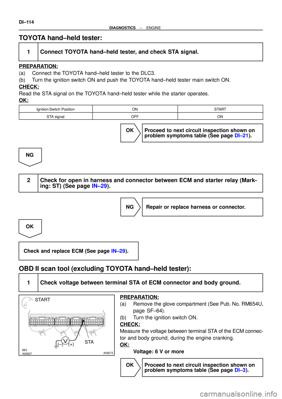
Measure the voltage between terminal STA of the ECM connec-
tor and body ground, during the engine cranking.
OK:
Voltage: 6 V or more
OK Proceed to next circuit inspection shown on
problem symptoms table (See page DI±3).
Page 2273 of 4592
A09405
E5
IG2 L±W1
L±R
THR5 V ECM
E2
E59
BR
IG23
BR A/C Evaporator
Temp. Sensor
2 110
A09290BE6653
A09361
ON
E1 THR
(±) (+)
± DIAGNOSTICSENGINE
DI±121
A/C Evaporator Temp. Sensor Circuit
CIRCUIT DESCRIPTION
This sensor detects the temperature inside the cooling unit and sends the appropriate signals to the ECM.
WIRING DIAGRAM
INSPECTION PROCEDURE
1 Check voltage between terminals THR and E2 of ECM connector.
PREPARATION:
(a) Remove the glove compartment (See Pub. No. RM654U,
page SF±64).
(b) Turn the ignition switch ON.
CHECK:
Measure the voltage between terminals THR and E1 of the
ECM connector at each temperature.
OK:
Voltage:
2.2 ± 2.6 V at 0°C (32 F)
1.4 ± 1.8 V at 15°C (59°F)
HINT:
As the temperature increases, the voltage decreases.
OK Check and replace ECM (See page IN±29).
DI01O±05
Page 2280 of 4592
A09304BE6653
A09431
#10#20 ON
#30#40
(±) (+)
FI6588
FI6538
A00064
Injector Signal Waveform
10 V/
Division
GND
100 msec./Division (Idling)GND
Injection duration1 msec./Division (Idling) 10 V/
Division(Magnification)
DI±128
± DIAGNOSTICSENGINE
2 Check spark plug and spark of misfiring cylinder (See page IG±1).
NG Replace or check ignition system
(See page IG±1).
OK
3 Check voltage of ECM terminals #10 ± #40 for injector of failed cylinder.
PREPARATION:
(a) Remove the glove compartment (See Pub. No. RM654U,
page SF±64).
(b) Turn the ignition switch ON.
CHECK:
Measure the voltage between applicable terminal of the ECM
connector and body ground.
OK:
Voltage: 9 ± 14 V
Reference: INSPECTION USING OSCILLOSCOPE
With the engine idling, check the waveform between terminals #10 ± #40 and E01 of the ECM connector.
HINT:
The correct waveforms are shown.
OK Go to step 5.
NG
Page 2286 of 4592

N09214
DLC3 DI±134
± DIAGNOSTICSAUTOMATIC TRANSAXLE
�The diagnosis system operates in normal mode
during normal vehicle use, and also has a check
mode for technicians to simulate malfunction symp-
toms and perform troubleshooting. Most DTCs use
2 trip detection logic(*) to prevent erroneous detec-
tion. By switching the ECM to check mode when
troubleshooting, the technician can cause the MIL
to light up and for a malfunction that is only detected
once or momentarily.
(hand±held tester) (See page DI±145)
�*2 trip detection logic:
When a logic malfunction is first detected, the mal-
function is temporarily stored in the ECM memory.
If the same malfunction is detected again during the
2nd test drive, this 2nd detection causes the MIL to
light up.
(b) Inspect the DLC3.
The vehicle's ECM uses V.P.W. (Variable Pulse Width) for
communication to comply with SAE J1850. The terminal
arrangement of DLC3 complies with SAE J1962 and
matches the V.P.W. format.
Tester connectionConditionSpecified condition
2 (Bus � Line) ± 5 (Signal ground)During communicationPulse generation
4 (Chassis Ground) ± BodyAlways1 W or less
5 (Signal Ground) ± BodyAlways1 W or less
16 (B+) ± BodyAlways9 ± 14 V
HINT:
If your display shows ºUNABLE TO CONNECT TO VEHICLEº
when you have connected the cable of OBD II scan tool or
hand±held tester to DLC3, turned the ignition switch ON and
operated the scan tool, there is a problem on the vehicle side
or tool side.
�If communication is normal when the tool is con-
nected to another vehicle, inspect DLC3 on the orig-
inal vehicle.
�If communication is still not possible when the tool
is connected to another vehicle, the problem is
probably in the tool itself, so consult the Service De-
partment listed in the tool's instruction manual.
Page 2313 of 4592
D02260
1 Shift Solenoid
Valve SLECM Transaxle
E1P8
E6SL
± DIAGNOSTICSAUTOMATIC TRANSAXLE
DI±161
DTC P0773 Shift Solenoid E Electrical Malfunction
(Shift Solenoid Valve SL)
CIRCUIT DESCRIPTION
The shift solenoid valve SL is turned ON and OFF by signals from the ECM to control the hydraulic pressure
acting on the lock±up relay valve, which then controls operation of the lock±up clutch.
Fail safe function
If the ECM detects a malfunction, it turns the shift solenoid valve SL OFF.
DTC No.DTC Detecting ConditionTrouble Area
P0773
Either (a) or (b) is detected for 1 time.(2 trip detection logic)
(a) Solenoid resistance is 8 W or less short circuit when sole-
noid is energized.
(b) Solenoid resistance is 100 kW or more open circuit when
solenoid is not energized.
�Open or short in shift solenoid valve SL circuit
�Shift solenoid valve SL
�ECM
WIRING DIAGRAM
DI035±05
Page 2319 of 4592

D06387
(+)NSW
(±)2R
L
Position
P, N
R
D
2
LNSW±Body
groundR±Body
ground2±Body
groundL±Body
ground
0 V
0 V0 V0 V
0 V
0 V
0 V 0 V
0 V
0 V 0 V
0 V
0 V 9 ± 14 V*
9 ± 14 V
9 ± 14 V
9 ± 14 V 9 ± 14 V*
9 ± 14 V
9 ± 14 V
± DIAGNOSTICSAUTOMATIC TRANSAXLE
DI±167
INSPECTION PROCEDURE
1 Read PNP, REVERSE, 2ND and LOW signals.
When using hand±held tester:
PREPARATION:
(a) Remove the DLC3 cover.
(b) Connect a hand±held tester to the DLC3.
(c) Turn the ignition switch to ON and hand±held tester main
switch ON.
CHECK:
Shift the shift lever into the P, R, N, 2 and L positions, and read
the PNP, REVERSE, 2ND and LOW signals on the hand±held
tester.
OK:
Shift positionSignal
22ND OFF " ON
LLOW OFF " ON
RREVERSE OFF " ON
P, NPNP OFF " ON
When not using hand±held tester:
PREPARATION:
Turn the ignition switch to ON.
CHECK:
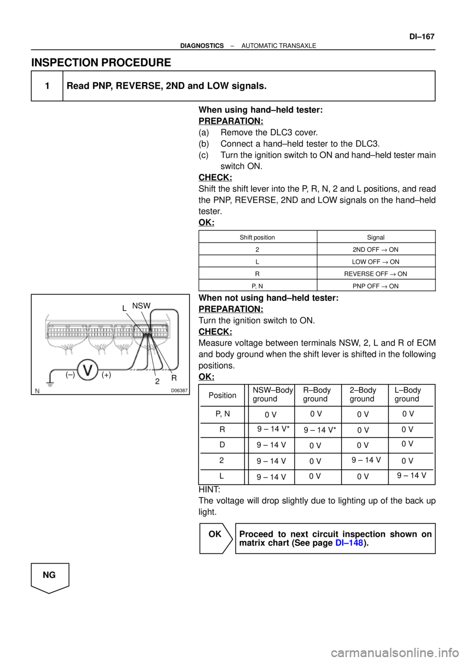
Measure voltage between terminals NSW, 2, L and R of ECM
and body ground when the shift lever is shifted in the following
positions.
OK:
HINT:
The voltage will drop slightly due to lighting up of the back up
light.
OK Proceed to next circuit inspection shown on
matrix chart (See page DI±148).
NG