Page 1827 of 4592
F00095
R±Y
3DLC1
J/CE1
ATs
J2211
II3 IK25
EC BRA15 BR
AR±Y
R±Y23 ABS & TRAC ECU
Ts
R±Y
3DLC1
J/CE1
ATs
J2211
II3 IK25
EC BRA15 BR
AR±Y
R±Y23 ABS & TRAC ECU
Ts
16
AB0119S08096
F00446
Ts
DLC1
E1
ON
± DIAGNOSTICSABS & TRACTION CONTROL SYSTEM
DI±615
850 Author�: Date�:
Ts Terminal Circuit
CIRCUIT DESCRIPTION
The sensor check circuit detects abnormalities in the speed sensor signal which cannot be detected with
the DTC check.
Connecting terminals Ts and E
1 of the DLC1 in the engine compartment starts the check.
WIRING DIAGRAM
INSPECTION PROCEDURE
1 Check voltage between terminals Ts and E1 of DLC1.
CHECK:
(a) Turn the ignition switch ON.
(b) Measure voltage between terminals Ts and E
1 of DLC1.
OK:
Voltage: 10 ± 14 V
OK If ABS warning light does not blink even after Ts
and E
1 are connected, the ECU may be defec-
tive.
NG
DI04X±04
Page 1968 of 4592

AB0119H01298H01299
(±) (+)ONAirbag Sensor Assembly
ACC
IG2
DI±756
± DIAGNOSTICSSUPPLEMENTAL RESTRAINT SYSTEM
991 Author�: Date�:
DTC B1100/31 Airbag Sensor Assembly Malfunction
CIRCUIT DESCRIPTION
The airbag sensor assembly consists of a airbag sensor, safing sensor, drive circuit, diagnosis circuit and
ignition control, etc.
It receives signals from the airbag sensor, judges whether or not the SRS must be activated, and detects
diagnosis system malfunction.
DTC B1100/31 is recorded when occurrence of a malfunction in the airbag sensor assembly is detected.
DTC No.DTC Detecting ConditionTrouble Area
B1100/31�Airbag sensor assembly malfunction�Airbag sensor assembly
INSPECTION PROCEDURE
HINT:
When a malfunction code other than code B1100/31 is displayed at the same time, first repair the malfunction
indicated by the malfunction code other than code B1100/31.
1 Prepare for inspection. (See step 1 on page DI±787)
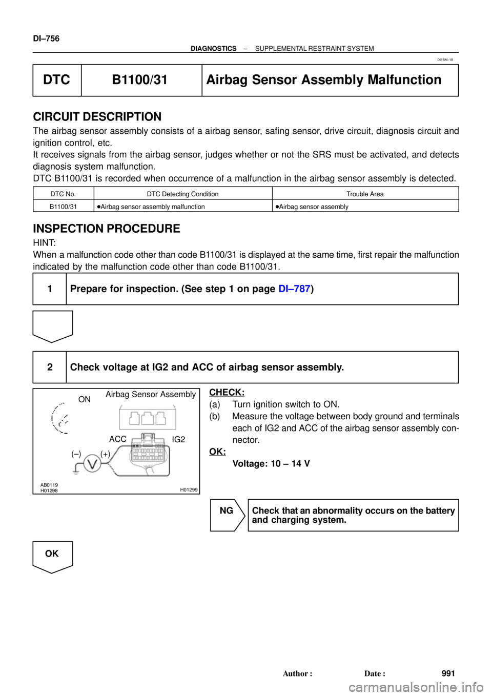
2 Check voltage at IG2 and ACC of airbag sensor assembly.
CHECK:
(a) Turn ignition switch to ON.
(b) Measure the voltage between body ground and terminals
each of IG2 and ACC of the airbag sensor assembly con-
nector.
OK:
Voltage: 10 ± 14 V
NG Check that an abnormality occurs on the battery
and charging system.
OK
DI1BM±18
Page 2027 of 4592

I08426
Wireless Door Lock ECU
Theft Deterrent ECU Integration Relay
UL3 R±G9
T4 I18
UL2 10
T4 UL27
W6R±G R±GI18
B
J6
J/C
3
IE1
74*1
19*25*1
20*2
B
B
B
R±G
R±G
Instrument Panel J/B
1G3
1V
IE 20J37 J/C
RH
J38 W±B
IE1
J/C AA W±B
*3W±B*3
W±B*4
32
UNLOCK LOCK
Door Key
Lock and
Unlock
SwitchLL
L AA
A
3IM1
32
1
UNLOCK LOCK
L
J39
J/C AA W±B
*3W±B*3
W±B*4
20 IM1W±B
1LH
IJ *1: w/o Theft Deterrent System
*2: w/ Theft Deterrent System
*3: TMC Made
*4: TMMK Made
± DIAGNOSTICSWIRELESS DOOR LOCK CONTROL SYSTEM
DI±815
1050 Author�: Date�:
Door Key Lock and Unlock Switch Circuit (Unlock Side)
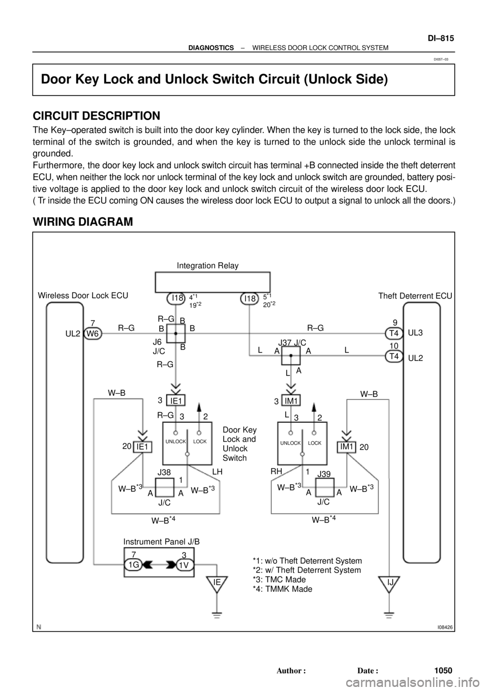
CIRCUIT DESCRIPTION
The Key±operated switch is built into the door key cylinder. When the key is turned to the lock side, the lock
terminal of the switch is grounded, and when the key is turned to the unlock side the unlock terminal is
grounded.
Furthermore, the door key lock and unlock switch circuit has terminal +B connected inside the theft deterrent
ECU, when neither the lock nor unlock terminal of the key lock and unlock switch are grounded, battery posi-
tive voltage is applied to the door key lock and unlock switch circuit of the wireless door lock ECU.
( Tr inside the ECU coming ON causes the wireless door lock ECU to output a signal to unlock all the doors.)
WIRING DIAGRAM
DI05T±03
Page 2042 of 4592

I00229
0.75 ± 0.1 sec.
1.25 ± 0.1 sec.
ON
OFF
Blinking Pattern Security only: DI±830
± DIAGNOSTICSTHEFT DETERRENT SYSTEM
1065 Author�: Date�:
4. CANCELLATION OF THEFT DETERRENT OPERA-
TION OR MODE
The theft deterrent operation of mode can be cancelled when
any of the following conditions is met.
No.ConditionCancel of OperationCancel of Mode
1Unlock front doors with the keyEffectiveEffective
2Unlock doors with remote keyless entryEffectiveEffective
3Insert key into ignition key cylinder and turn
it to ACC or ON positionEffectiveEffective
4About 1 minute passes after theft deterrent
operation beginsAutomatic stop *1±
5Unlock the luggage compartment door with
the key or keyless entry.UneffectiveEffective
6Unlock the luggage compartment door with
the keyless entry.UneffectiveEffective
7
If the system receives panic signal again or
unlock signal when the system is activated
by panic signal
Effective *2Uneffective
6If the system receives unlock signal when
the system is activated by panic signalEffectiveEffective
*1: The system is set to the theft deterrent mode again in
about 2 seconds after the operation stops, if all doors are
closed.
*2: The alarm caused by the panic signal malces the sys-
tem in the previous condition.
5. INDICATOR LIGHT (LED)
The indicator light functions as shown below according to the
system condition in the theft deterrent mode. It remains OFF in
the initial state.
System ConditionIndicator Light
During set preparation timeON
When the mode is set*OFF
When alarm is activatedON
When the system is temporally cancelled*OFF
*: The indicator flashes with the output from the immobiliser.
6. KEEPING POWER SUPPLY FUNCTION IN CASE OF
DOME FUSE OPEN
Even if the dome fuse blows open on the theft deterrent mode,
the system will keep working on the theft deterrent mode.
Page 2043 of 4592

Remove the ignition key from key cylinder.
All the doors, engine hood and luggage
compartment door are closed and unlocked.
Any of doors is locked and unlocked by turns
3 times by the key or remote control.
Driver 's side knob for doorlock is locked and
unlocked 3 times.
Driver's side doors is opened.
The system starts force lock at once after 2
sec.
Driver's side knob for door lock is unlocked.
Driver's side door is closed and opened 2
times
Driver's side knob for door lock is locked and
unlocked.
The system starts force lock at once after 2
sec.
PASSIVE MODE OFF
Driver's side door is closed and opened 4
times
Driver's side knob for door lock is locked and
unlocked.
The system starts force lock at once after 2
sec.
PASSIVE MODE ON
Within
30 sec.
Within
20 sec.
HINT:
� Initial mode is PASSIVE MODE OFF.
� If there is a different signal in the middle of changing, it is invalied.
Input to the vehicle
Output from the vehicle
± DIAGNOSTICSTHEFT DETERRENT SYSTEM
DI±831
1066 Author�: Date�:
7. CHANGING METHOD OF PASSIVE MODE
(ON or OFF)
Page 2048 of 4592

DI±836
± DIAGNOSTICSTHEFT DETERRENT SYSTEM
1071 Author�: Date�:
+B1 e Body ground
(T4±12 eBody ground)R eW±BAlways10 ± 14 V
IG e E
(T4±13 e T3±7)B±R e W±BIgnition switch is turned to ºONº position10 ± 14 V
LSWD e ELRWB
Door unlock detection switch ºONº
(Driver's door)Below 1 WLSWD e E
(T4±14 e T3±7)L±R e W±BDoor unlock detection switch ºOFFº
(Driver's door)1 MW or higher
LSWP e EYWB
Door unlock detection switch ºONº
(Passenger's door)Below 1 WLSWP e E
(T4±15 e T3±7)Y e W±BDoor unlock detection switch ºOFFº
(Passenger's door)1 MW or higher
LSWR e ELYWB
Door unlock detection switch ºONº
(Rear door)Below 1 WLSWR e E
(T4±16 e T3±7)L±Y e W±BDoor unlock detection switch ºOFFº
(Rear door)1 MW or higher
PANI e ELGWBIt is receiving panic signal from remote keyless entryBelow 1 WPANI e E
(T4±18 e T3±7)LG e W±BExcept above mention1 MW or hegher
+B2 e Body ground
(T3±1 e Body ground)L±W e Body
groundAlways10 ± 14 V
IND e E
(T3±6 e T3±7)R±Y eW±BDuring set preparation3 ± 5 V
E e Body ground
(T3±7 e Body ground)W±B e Body
groundAlways10 ± 14 V
SH e E
(T3±9 e T3±7)W±L e W±BAlways10 ± 14 V
HEAD e E
(T3±10 e T3±7)R±B e W±BLight control switch ºHEADº10 ± 14 V
TA I L e E
(T3±11 e T3±7)G±R e W±BLight control switch ºTAILº or ºHEADº10 ± 14 V
HORN e E
(T3±12 e T3±7)G±B e W±BHorn switch ºOFFº10 ± 14 V
Page 2086 of 4592

N17520
(1)
(2)
(1)
No.Operation MethodCRUISE MAIN Indicator Light
Blinking PatternDiagnosis
1 Turn SET/COAST switch ON
2Turn RES/ACC switch ON
3Turn CANCEL switch ON
Turn stop light switch ON
Depress brake pedal
Turn PNP switch OFF
(Shift to except D position)
4Drive at about 40 km/h
(25 mph)or higher
Drive at about 40 km/h
(25 mph) or below
LightON
OFF
LightON
OFF
LightON
OFFSwitch ON
Switch OFF
LightON
OFFSwitch OFF
Switch ONSET/COAST switch circuit
is normal
RES/ACC switch circuit
is normal
CANCEL switch circuit
is normal
Stop light switch circuit
is normal
PNP switch circuit is
normal
Vehicle Speed Sensor is
normal
LightON
OFF LightON
OFF
1sec.
0.25 sec.0.25 sec.
Turn clutch switch OFF
(Depress clutch pedal)Clutch switch circuit
is normal
DI±874
± DIAGNOSTICSCRUISE CONTROL SYSTEM
1109 Author�: Date�:
5. INPUT SIGNAL CHECK
HINT:
(1) For check No.1 ~ No.3
�Turn ignition switch ON.
(2) For check No.4
�Jack up the vehicle.
�Start the engine.
�Shift to D position.
(a) Pull the control switch to SET/COAST or RES/ACC posi-
tion and hold it down or up (1).
(b) Push the main switch ON (2).
(c) Check that the CRUISE MAIN indicator light blinks twice
or 3 times repeatedly after 3 seconds.
(d) Turn the SET/COAST or RES/ACC switch OFF.
(e) Operate each switch as listed in the table below.
(f) Read the blinking pattern of the CRUISE MAIN indicator
light.
(g) After performing the check, turn the main switch OFF.
HINT:
When 2 or more signals are input to the ECU, the lowest num-
bered code will be displayed first.
Page 2095 of 4592

I00281
Cruise Control ECU
C15
G±B
2 1 34W±B
3
STOP Fuse8 Stop Light Switch
4
R±Y
Stop Lights Cruise Control Actuator
� Actuator Magnetic Clutch
J7
J7AAJ/C
W±B
1J
1J
W±B
A
J/C
IG 8
7
J11Instrument
Panel J/BL
± DIAGNOSTICSCRUISE CONTROL SYSTEM
DI±883
111 8 Author�: Date�:
DTC 12 Actuator Magnetic Clutch Circuit
CIRCUIT DESCRIPTION
This circuit turns on the magnetic clutch inside the actuator during cruise control operation according to the
signal from the ECU. If a malfunction occurs in the actuator or speed sensor, etc. during cruise control opera-
tion, the rotor shaft between the motor and control plate is released.
When the brake pedal is depressed, the stop light switch turns on, supplying electrical power to the stop light.
Power supply to the magnetic clutch is mechanically cut and the magnetic clutch is turned OFF.
When driving downhill, if the vehicle speed exceeds the set speed by 15 km/h (9 mph), the ECU turns the
safety magnet clutch OFF. If the vehicle speed later drops to within 10 km/h (6 mph), cruise control at the
set speed is resumed.
DTC No.Detection ItemTrouble Area
12Short in actuator magnetic clutch circuit.
Open (0.8 sec.) in actuator magnetic clutch circuit.
�STOP Fuse
�Stop light switch
�Actuator magnetic clutch
�Harness or connector between cruise control ECU and
actuator magnetic clutch, actuator magnetic clutch and body
ground
�Cruise control ECU
WIRING DIAGRAM
DI08N±12