Page 1565 of 4592
A02033
ON
IGF (+)
± DIAGNOSTICSENGINE (1MZ±FE)
DI±353
588 Author�: Date�:
2 Check for open and short in harness and connector in IGF signal circuit between
ECM and igniter (See page IN±31).
NG Repair or replace harness or connector.
OK
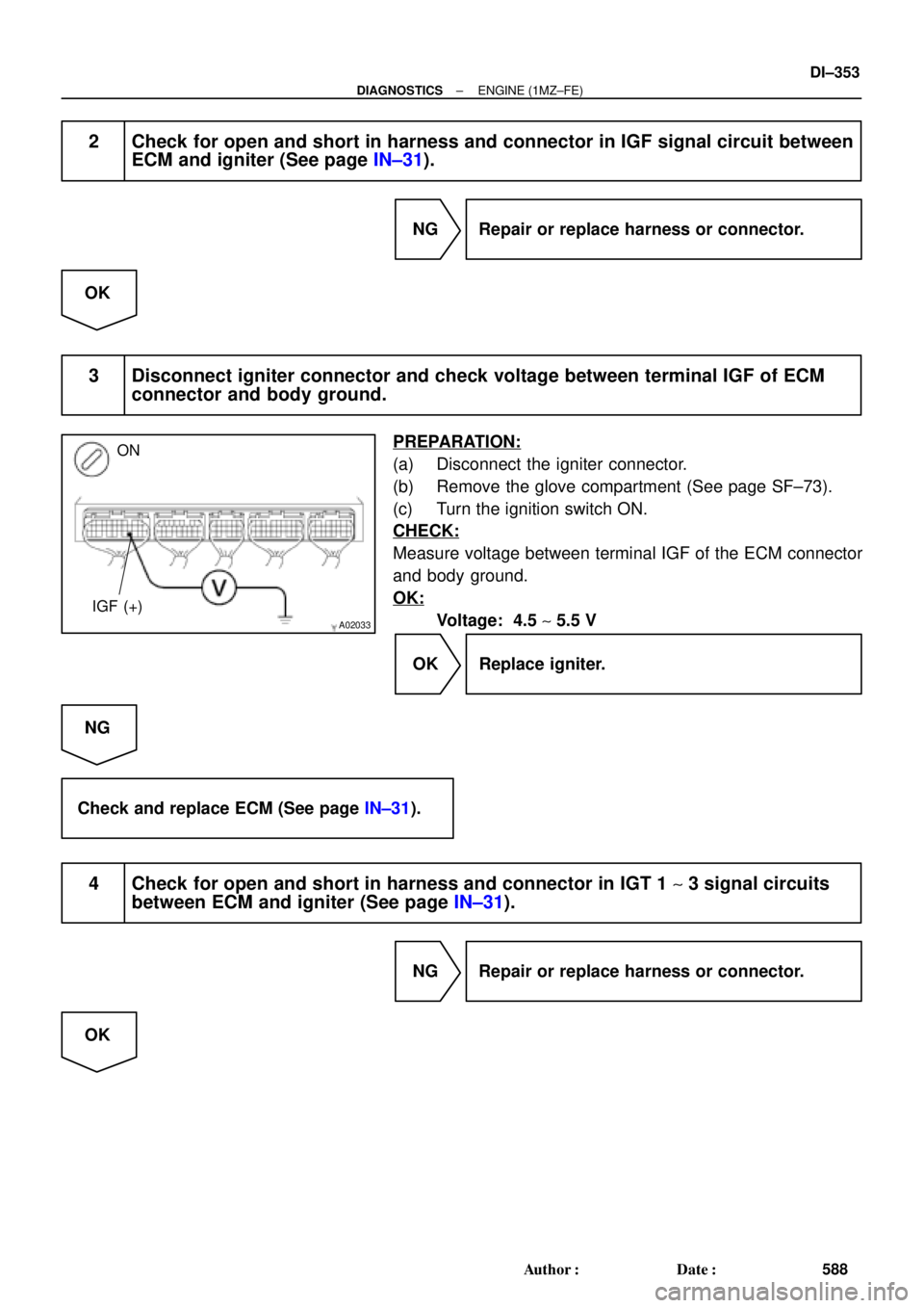
3 Disconnect igniter connector and check voltage between terminal IGF of ECM
connector and body ground.
PREPARATION:
(a) Disconnect the igniter connector.
(b) Remove the glove compartment (See page SF±73).
(c) Turn the ignition switch ON.
CHECK:
Measure voltage between terminal IGF of the ECM connector
and body ground.
OK:
Voltage: 4.5 ~ 5.5 V
OK Replace igniter.
NG
Check and replace ECM (See page IN±31).
4 Check for open and short in harness and connector in IGT 1 ~ 3 signal circuits
between ECM and igniter (See page IN±31).
NG Repair or replace harness or connector.
OK
Page 1575 of 4592
A07449
Fusible
Link
Block
FL
MAINStop Light Switch
B±G1B 1CSTOP
WG±WLight
Failure
Sensor 7
2
To Stop Light Instrument Panel J/B
Instrument Panel J/B
E7 15
G±W
1S 1R
1R1
2
F9
F4
BatteryECM
STP
E1 B±R
ALT
G±WA
C
J27Junction
Connector
J2845
2
G±W7 4
1
1
± DIAGNOSTICSENGINE (1MZ±FE)
DI±363
598 Author�: Date�:
DTC P1520 Stop Light Switch Signal Malfunction
(Only for A/T)
CIRCUIT DESCRIPTION
This signal is used to detect when the brakes have been applied. The STP signal voltage is the same as
the voltage supplied to the stop lights.
The STP signal is used mainly to control the fuel cut±off engine speed (The fuel cut±off engine speed is re-
duced slightly when the vehicle is braking.).
DTC No.DTC Detecting ConditionTrouble Area
P1520
Stop light switch does not turn off when repeating the driving at
30 km or more 10 times or more after depressing brake
(2 trip detection logic)�Short in stop light switch signal circuit
�Stop light switch
�ECM
WIRING DIAGRAM
DI088±06
Page 1576 of 4592

DI±364
± DIAGNOSTICSENGINE (1MZ±FE)
599 Author�: Date�:
INSPECTION PROCEDURE
HINT:
Read freeze frame data using TOYOTA hand±held test")
A02037
ON
ON
Brake Pedal
DepressedBrake Pedal
Released
STP (+)
DI±364
± DIAGNOSTICSENGINE (1MZ±FE)
599 Author�: Date�:
INSPECTION PROCEDURE
HINT:
Read freeze frame data using TOYOTA hand±held tester or OBD II scan tool. Because freeze frame records
the engine conditions when the malfunction is detected, when troubleshooting it is useful for determining
whether the vehicle was running or stopped, the engine warmed up or not, the air±fuel ratio lean or rich, etc.
at the time of the malfunction.
1 Check operation of stop light.
CHECK:
Check if the stop lights go on and off normally when the brake pedal is operated and released.
NG Check and repair stop light circuit.
OK
2 Check STP signal.
When using TOYOTA hand±held tester:
PREPARATION:
(a) Connect the TOYOTA hand±held tester to the DLC3.
(b) Turn the ignition switch ON and push the TOYOTA hand±
held tester main switch ON.
CHECK:
Read the STP signal on the TOYOTA hand±held tester.
OK:
Brake pedal is depressed: STP ...... ON
Brake pedal is released: STP ...... OFF
When not using TOYOTA hand±held tester:
PREPARATION:
Turn the ignition switch ON.
CHECK:
Check voltage between terminal STP of the ECM connector
and body ground.
OK:
Brake pedalVoltage
Depressed7.5 ~ 14 V
ReleasedBelow 1.5 V
OK Check for intermittent problems
(See page DI±197).
NG
Page 1581 of 4592

A07450
Ignition SwitchW±R B±RInstrument Panel J/B
FL
MAINFusible
Link
Block
BatteryJunction
ConnectorECM
B±R
W±R
BR
BR
W±B
B±Y
B
6
7
2 4
17
2 5
4
1 1B
AA F4 F6 E10E7
2F 2K 2J
2L
2AEFI EFI
RelayEngine Room
J/B+B
E1 17 16
AM2
EB EC
J28
3
1E72
MREL
E78IGSW
J27
1W
1B7
5 IGN
1K3
1K5
B+ B
B±Y
B±W
B±W
J35 J35
C
C
Junction
Connector
B±GJ22
Junction
Connector
± DIAGNOSTICSENGINE (1MZ±FE)
DI±369
604 Author�: Date�:
ECM Power Source Circuit
CIRCUIT INSPECTION
When the ignition switch is turned on, battery positive voltage is applied to terminal IGSW of the ECM and
the EFI main relay (Marking: EFI) control circuit in the ECM sends a signal to terminal MREL of the ECM
switching on the EFI main relay.
This signal causes current to flow to the coil, closing the contacts of the EFI, main relay and supplying power
to terminals +B of the ECM.
If the ignition switch is turned off, the ECM continues to switch on the EFI main relay for a maximum of 2
seconds for the initial setting of the IAC valve.
WIRING DIAGRAM
DI4DU±01
Page 1586 of 4592
A07151
Fuel Pump Circuit Opening Relay
EFI Main Relay
FC
Tr
MREL
IGSW
STA EFI
NEECM
Starter Starter Relay MAIN
Battery AM2IG Switch
(NE Signal) (STA Signal) Park/ Neutral Position Switch IGN
STARTER DI±374
± DIAGNOSTICSENGINE (1MZ±FE)
609 Author�: Date�:
Fuel Pump Control Circuit
CIRCUIT DESCRIPTION
In the diagram below, when the engine is cranked, current flows from terminal ST of the ignition switch to
the starter relay coil and also current flows to terminal STA of ECM (STA signal).
When the STA signal and NE signal are input to the ECM, Tr is turned ON, current flows to coil of the circuit
opening relay, the relay switches on, power is supplied to the fuel pump and the fuel pump operates.
While the NE signal is generated (engine running), the ECM keeps Tr ON (circuit opening relay ON) and the
fuel pump also keeps operating.
DI4DV±01
Page 1588 of 4592
A00244
ON
BE6653
P20186
DI±376
± DIAGNOSTICSENGINE (1MZ±FE)
611 Author�: Date�:
INSPECTION PROCEDURE
TOYOTA hand±held tester
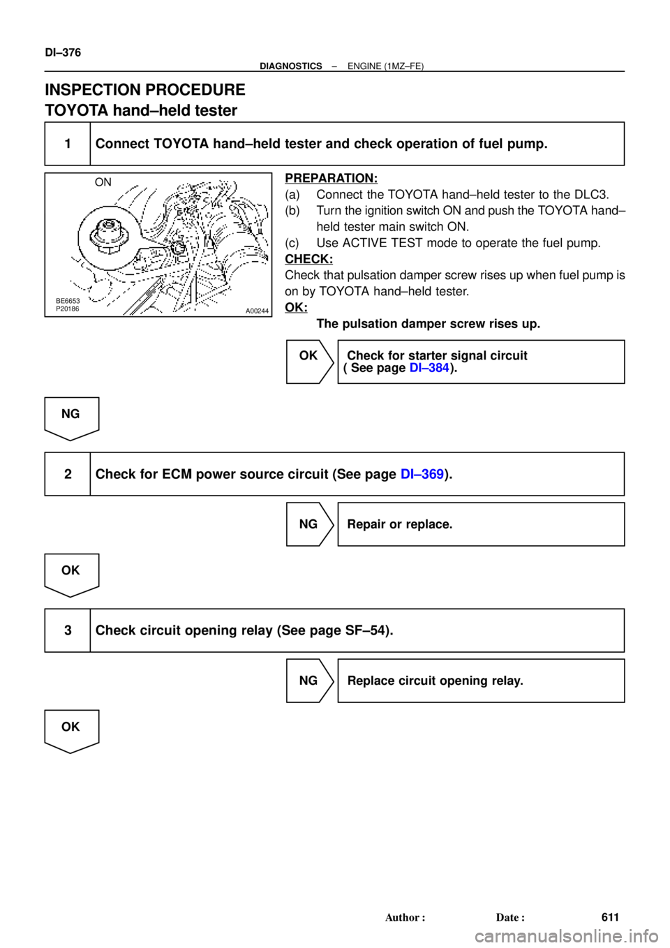
1 Connect TOYOTA hand±held tester and check operation of fuel pump.
PREPARATION:
(a) Connect the TOYOTA hand±held tester to the DLC3.
(b) Turn the ignition switch ON and push the TOYOTA hand±
held tester main switch ON.
(c) Use ACTIVE TEST mode to operate the fuel pump.
CHECK:
Check that pulsation damper screw rises up when fuel pump is
on by TOYOTA hand±held tester.
OK:
The pulsation damper screw rises up.
OK Check for starter signal circuit
( See page DI±384).
NG
2 Check for ECM power source circuit (See page DI±369).
NG Repair or replace.
OK
3 Check circuit opening relay (See page SF±54).
NG Replace circuit opening relay.
OK
Page 1590 of 4592
A02042
ON
FC
DI±378
± DIAGNOSTICSENGINE (1MZ±FE)
613 Author�: Date�:
OBD II scan tool (excluding TOYOTA hand±held tester)
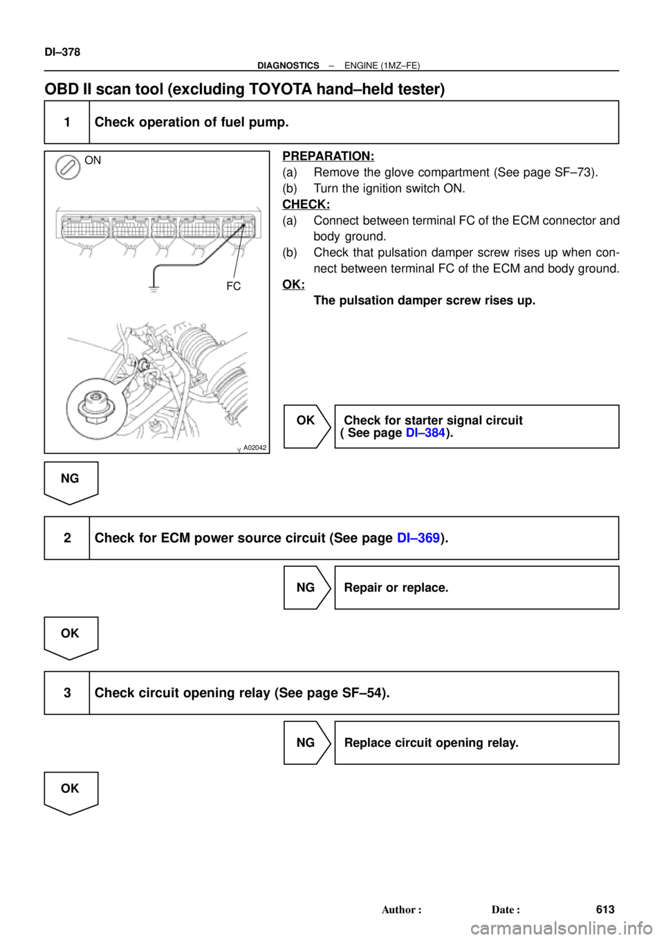
1 Check operation of fuel pump.
PREPARATION:
(a) Remove the glove compartment (See page SF±73).
(b) Turn the ignition switch ON.
CHECK:
(a) Connect between terminal FC of the ECM connector and
body ground.
(b) Check that pulsation damper screw rises up when con-
nect between terminal FC of the ECM and body ground.
OK:
The pulsation damper screw rises up.
OK Check for starter signal circuit
( See page DI±384).
NG
2 Check for ECM power source circuit (See page DI±369).
NG Repair or replace.
OK
3 Check circuit opening relay (See page SF±54).
NG Replace circuit opening relay.
OK
Page 1597 of 4592
± DIAGNOSTICSENGINE (1MZ±FE)
DI±385
620 Author�: Date�:
INSPECTION PROCEDURE
HINT:
This diagnostic chart is based on the premise that the engine is cranked normally. If the engine is not
cranked, proceed to the problem symptoms table on page DI±221.
TOYOTA hand±held tester
1 Connect TOYOTA hand±held tester, and check STA signal.
PREPARATION:
(a) Connect the TOYOTA hand±held tester to the DLC3.
(b) Turn the ignition switch ON and push the TOYOTA hand±held tester main switch ON.
CHECK:
Read STA signal on the TOYOTA hand±held tester while starter operates.
OK:
Ignition switch positionONSTART
STA signalOFFON
OK Proceed to next circuit inspection shown on
problem symptom table (See page DI±221).
NG
2 Check for open in harness and connector between ECM and starter relay
(See page IN±31).
NG Repair or replace or connector.
OK
Check and replace ECM (See page IN±31).

 (STA Signal) Park/ Neutral Position Switch IGN
STARTER D")