Page 3516 of 4592
F01476
Key Unlock Warning Switch
Column Upper Bracket Ignition Switch
Energy Absorbing PlateTransponder Key Coil Key Cylinder Lamp Assembly
Key
Interlock
Solenoid Key Cylinder
Transponder Key
Amplifier
Energy Absorbing Plate
Guide� Energy Absorbing Clip
Energy Absorbing Plate
Energy Absorbing Plate
Guide
� Energy Absorbing Clip Column TubeTilt Lever
Return Spring
� Tapered±Head Bolt Column Upper Tube Turn Signal Bracket
Lower Column Tube AttachmentColumn Tube Support
7 (70, 61 in.´lbf)
19 (195, 14)
N´m (kgf´cm, ft´lbf): Specified torque
� Non±reusable partw/ ENGINE IMMOBILISER SYSTEM:
A/T: SR±10
± STEERINGTILT STEERING COLUMN
2105 Author�: Date�:
Page 3519 of 4592
SR06J±01
W03333
Screw Extractor
W03334
± STEERINGTILT STEERING COLUMN
SR±13
2108 Author�: Date�:
DISASSEMBLY
NOTICE:
When using a vise, do not overtighten it.
1. w/ ENGINE IMMOBILISER SYSTEM:
REMOVE TRANSPONDER KEY COIL WITH KEY CYL-
INDER LAMP ASSEMBLY
Remove the screw.
2. w/ ENGINE IMMOBILISER SYSTEM:
REMOVE KEY CYLINDER LAMP ASSEMBLY
Remove the lamp assembly from the key coil.
3. w/o ENGINE IMMOBILISER SYSTEM:
REMOVE KEY CYLINDER LAMP ASSEMBLY
Remove the screw.
4. REMOVE COLUMN UPPER BRACKET AND COLUMN
UPPER CLAMP
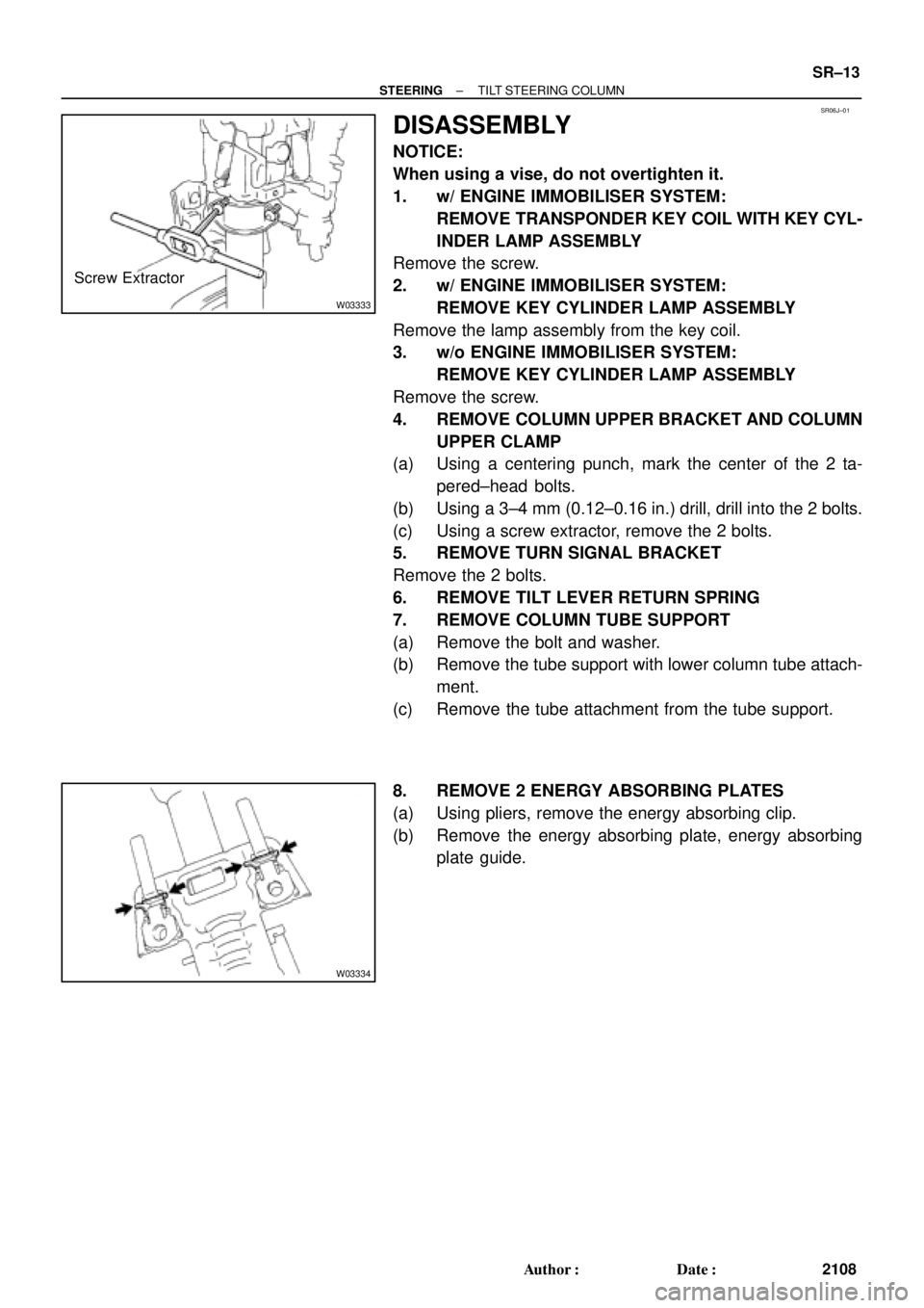
(a) Using a centering punch, mark the center of the 2 ta-
pered±head bolts.
(b) Using a 3±4 mm (0.12±0.16 in.) drill, drill into the 2 bolts.
(c) Using a screw extractor, remove the 2 bolts.
5. REMOVE TURN SIGNAL BRACKET
Remove the 2 bolts.
6. REMOVE TILT LEVER RETURN SPRING
7. REMOVE COLUMN TUBE SUPPORT
(a) Remove the bolt and washer.
(b) Remove the tube support with lower column tube attach-
ment.
(c) Remove the tube attachment from the tube support.
8. REMOVE 2 ENERGY ABSORBING PLATES
(a) Using pliers, remove the energy absorbing clip.
(b) Remove the energy absorbing plate, energy absorbing
plate guide.
Page 3521 of 4592
SR06L±01
W03347
W03337
± STEERINGTILT STEERING COLUMN
SR±15
2110 Author�: Date�:
REASSEMBLY
NOTICE:
When using a vise, do not overtighten it.
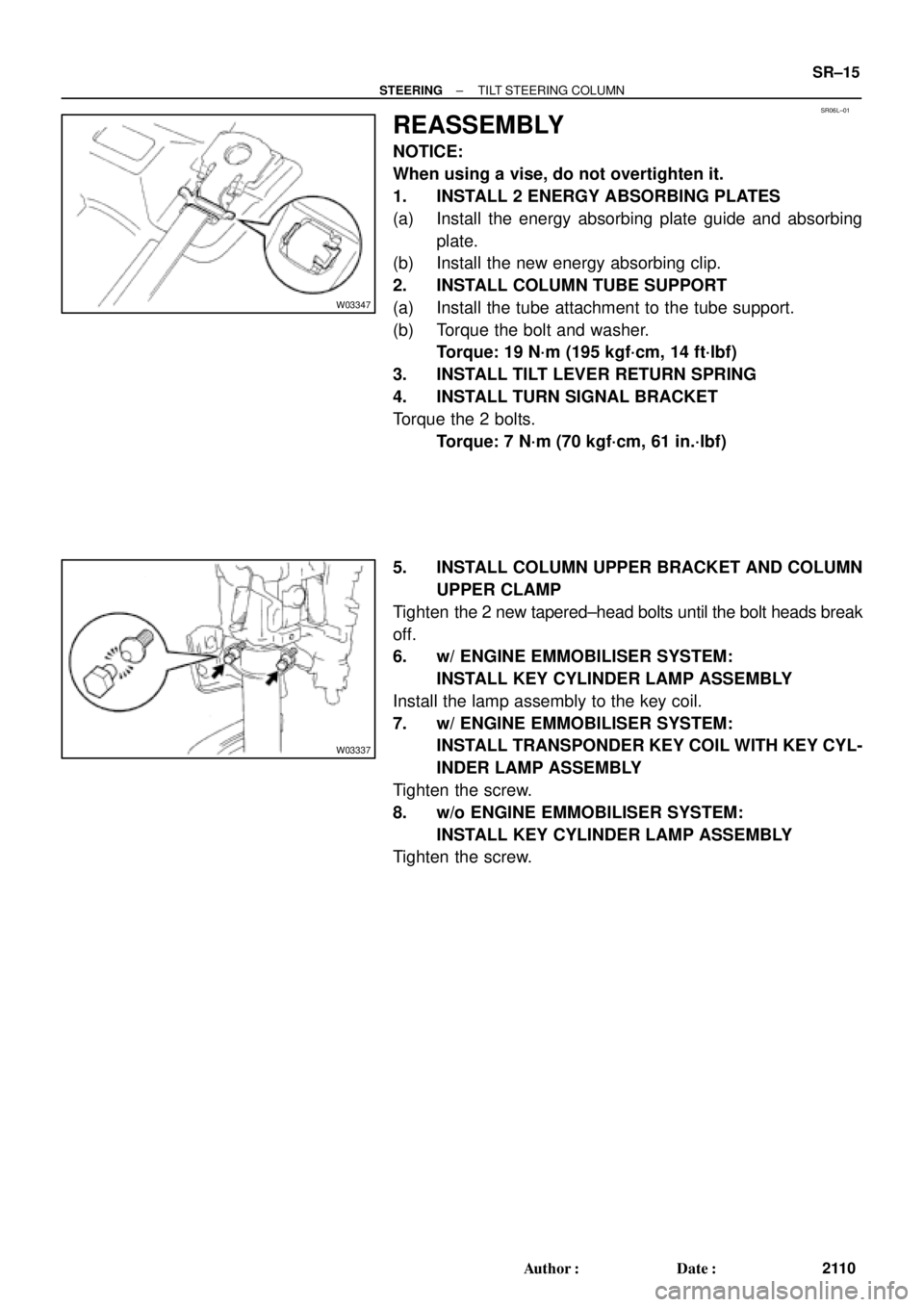
1. INSTALL 2 ENERGY ABSORBING PLATES
(a) Install the energy absorbing plate guide and absorbing
plate.
(b) Install the new energy absorbing clip.
2. INSTALL COLUMN TUBE SUPPORT
(a) Install the tube attachment to the tube support.
(b) Torque the bolt and washer.
Torque: 19 N´m (195 kgf´cm, 14 ft´lbf)
3. INSTALL TILT LEVER RETURN SPRING
4. INSTALL TURN SIGNAL BRACKET
Torque the 2 bolts.
Torque: 7 N´m (70 kgf´cm, 61 in.´lbf)
5. INSTALL COLUMN UPPER BRACKET AND COLUMN
UPPER CLAMP
Tighten the 2 new tapered±head bolts until the bolt heads break
off.
6. w/ ENGINE EMMOBILISER SYSTEM:
INSTALL KEY CYLINDER LAMP ASSEMBLY
Install the lamp assembly to the key coil.
7. w/ ENGINE EMMOBILISER SYSTEM:
INSTALL TRANSPONDER KEY COIL WITH KEY CYL-
INDER LAMP ASSEMBLY
Tighten the screw.
8. w/o ENGINE EMMOBILISER SYSTEM:
INSTALL KEY CYLINDER LAMP ASSEMBLY
Tighten the screw.
Page 3657 of 4592
Vehicles with power antennas may exhibit audible electrical noise on weak AM stations when
various electrical accessories (turn signals, rear defogger, cruise control, brakes, etc.) are operated.
Poor antenna grounding can cause this condition.
To eliminate or reduce the intensity of the noise, use the following repair procedure:
AM STATIC NOISE ON VEHICLES WITH POWER ANTENNASPage 1 of 2
OCTOBER 25, 1996
AUDIO
AU002±96
ALL MODELS
REPAIR PROCEDURE:
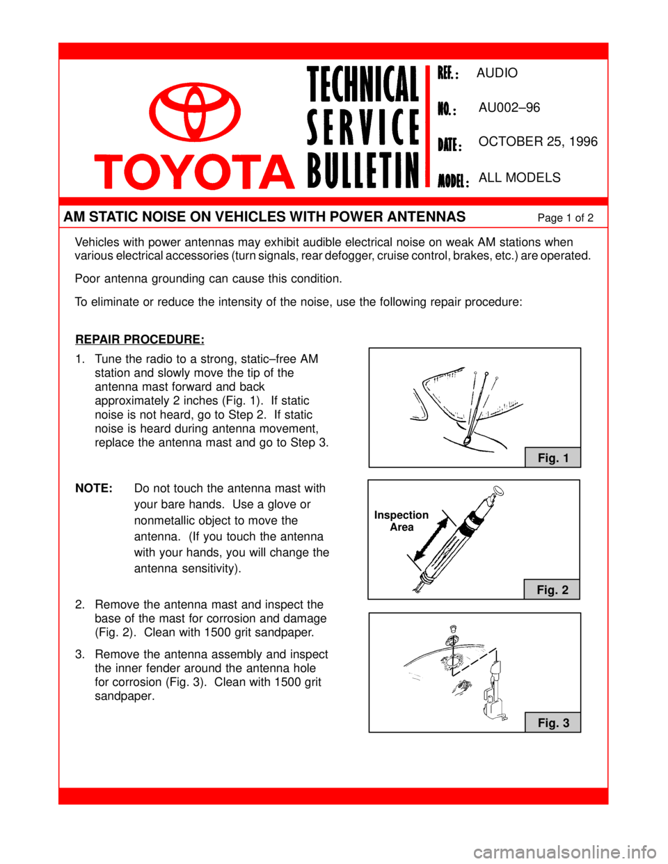
1. Tune the radio to a strong, static±free AM
station and slowly move the tip of the
antenna mast forward and back
approximately 2 inches (Fig. 1). If static
noise is not heard, go to Step 2. If static
noise is heard during antenna movement,
replace the antenna mast and go to Step 3.
NOTE:Do not touch the antenna mast with
your bare hands. Use a glove or
nonmetallic object to move the
antenna. (If you touch the antenna
with your hands, you will change the
antenna sensitivity).
2. Remove the antenna mast and inspect the
base of the mast for corrosion and damage
(Fig. 2). Clean with 1500 grit sandpaper.
3. Remove the antenna assembly and inspect
the inner fender around the antenna hole
for corrosion (Fig. 3). Clean with 1500 grit
sandpaper.
Fig. 1
Fig. 2
Fig. 3
Inspection
Area
Page 3806 of 4592
EVAP SYSTEM OPERATION INFORMATION ± EG005-01 April 27, 2001
Page 8 of 14
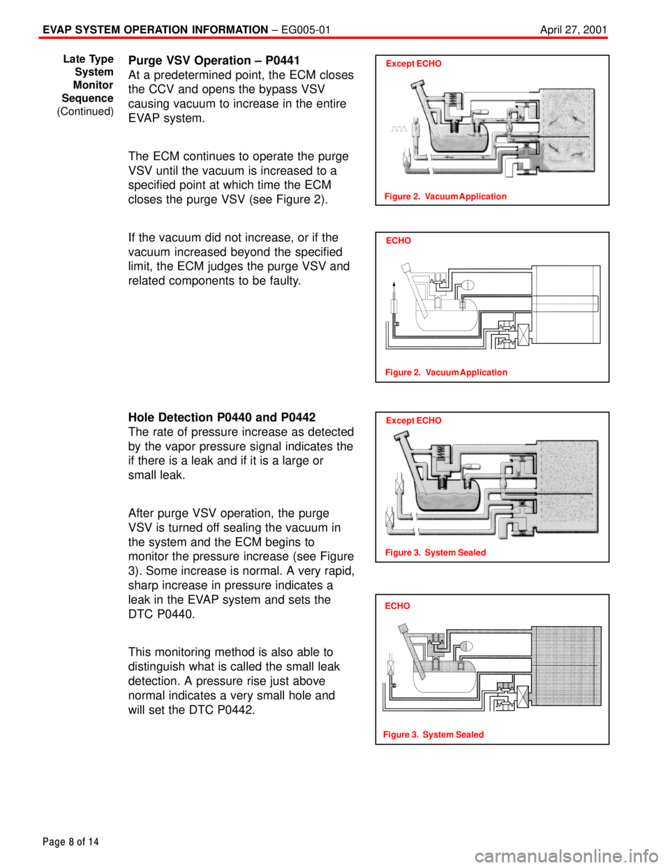
Purge VSV Operation ± P0441
At a predetermined point, the ECM closes
the CCV and opens the bypass VSV
causing vacuum to increase in the entire
EVAP system.
The ECM continues to operate the purge
VSV until the vacuum is increased to a
specified point at which time the ECM
closes the purge VSV (see Figure 2).
If the vacuum did not increase, or if the
vacuum increased beyond the specified
limit, the ECM judges the purge VSV and
related components to be faulty.
Hole Detection P0440 and P0442
The rate of pressure increase as detected
by the vapor pressure signal indicates the
if there is a leak and if it is a large or
small leak.
After purge VSV operation, the purge
VSV is turned off sealing the vacuum in
the system and the ECM begins to
monitor the pressure increase (see Figure
3). Some increase is normal. A very rapid,
sharp increase in pressure indicates a
leak in the EVAP system and sets the
DTC P0440.
This monitoring method is also able to
distinguish what is called the small leak
detection. A pressure rise just above
normal indicates a very small hole and
will set the DTC P0442.Except ECHO
Figure 2. Vacuum Application
Late Type
System
Monitor
Sequence
(Continued)
ECHO
Figure 2. Vacuum Application
Except ECHO
Figure 3. System Sealed
ECHO
Figure 3. System Sealed
Page 3826 of 4592
Toyota Supports ASE CertificationPage 1 of 1
EL006±99Title:
ENGINE IMMOBILIZER SYSTEM
PRECAUTIONS
Models:
All Models
Technical Service
BULLETIN
October 8, 1999
REVISION NOTICE:
The information contained in this TSB updates EL001±98 dated January 23, 1998.
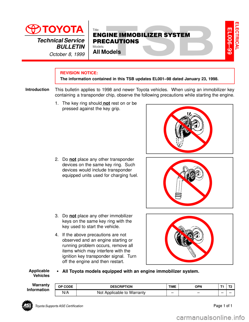
This bulletin applies to 1998 and newer Toyota vehicles. When using an immobilizer key
containing a transponder chip, observe the following precautions while starting the engine.
1. The key ring should not
rest on or be
pressed against the key grip.
2. Do not
place any other transponder
devices on the same key ring. Such
devices would include transponder
equipped units used for charging fuel.
3. Do not
place any other immobilizer
keys on the same key ring with the
key used to start the vehicle.
4. If the above precautions are not
observed and an engine starting or
running problem occurs, remove all
items which may interfere with the
ignition key transponder signal. Turn
off the engine and then restart.
�All Toyota models equipped with an engine immobilizer system.
OP CODEDESCRIPTIONTIMEOPNT1T2
N/ANot Applicable to Warranty±±±±
ELECTRICAL
Introduction
Applicable
Vehicles
Warranty
Information
Page 4017 of 4592
B HOW TO USE THIS MANUAL
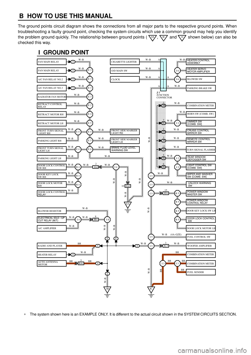
The ground points circuit diagram shows the connections from all major parts to the respective ground points. When
troubleshooting a faulty ground point, checking the system circuits which use a common ground may help you identify
the problem ground quickly. The relationship between ground points (
EA, IB and IC shown below) can also be
checked this way.
���� ���� ���� ���� ���� ���� ���� ���� ���� ���� ���� ���� ���� ���� ���� ���� ���� ���� ����
I GROUND POINT
FAN MAIN RELAY
FAN MAIN RELAY
A/C FAN RELAY NO.2
A/C FAN RELAY NO.3
RADIATOR FAN MOTOR
RETRACT CONTROL
RELAY
RETRACT MOTOR RH
RETRACT MOTOR LH
FRONT TURN SIGNAL
LIGHT RH
PARKING LIGHT RH
FRONT TURN SIGNAL
LIGHT LH
PARKING LIGHT LH
DOOR LOCK CONTROL
SW RH
DOOR KEY LOCK
SW RH
DOOR LOCK MOTOR
RH
BLOWER RESISTOR
A/C AMPLIFIER
RADIO AND PLAYER
HEATER RELAY
AUTO ANTENNA
MOTOR
BLOWER SW
PARKING BRAKE SW
COMBINATION METER
HORN SW [COMB. SW]
TURN SIGNAL FLASHER
DOOR KEY LOCK SW LH
DOOR LOCK MOTOR LH
FUEL CONTROL SW
WOOFER AMPLIFIER
COMBINATION METER
COMBINATION METER
FUEL SENDER
CIGARETTE LIGHTER
O/D MAIN SW
CLOCK
5
5
5
5
4
4
4
4
4BA15
IB18
EA2 10
3E5
3E
6 3G
13 3F
3 3D
1 3B
7
ID115
IC33
IA12
E 3
A
A AW±B
W±BW±B W±B
W±B W±B
W±B
W±B
W±B
W±B
W±B
W±B
W±B
W±B
W±B W±BW±B W±B W±B W±B
W±B W±B
W±BW±B
W±B
W±B
W±B W±B
W±B
BR
W±B
BR BRW±BW±B
W±B
W±B
W±B
W±B
W±B
W±B
W±B
W±B
W±B W±B
W±B
W±B
W±B
W±B
BR W±B
BR BR
BR W±B W±BW±B
W±BW±BBR W±B (4A±GZE)
W±B A A A
I 6
I 6
I 2
I 2
I 2
B 5I 5
I 5
I 5
B 5
B 5
B 5
I 5
I 5
I 3I 3
E 3
E 3
E 3
E 2
E 4
E 5
E 4
E 5
E 6E 4
E 4
B 4
EAI 4
B 4
B 4
I 4I 8
IBIC
3C7
4
JUNCTION
CONNECTOR J 1
4
DOOR LOCK CONTROL
RELAY
ELECTRICAL IDLE-UP
CUT RELAY (M/T)FRONT SIDE MARKER
LIGHT RH
FRONT SIDE MARKER
LIGHT LH
BRAKE FLUID LEVEL
WARNING SW
UNLOCK WARNING
SW WIPER AND WASHER
SW [COMB. SW] LIGHT CONTROL SW
[COMB. SW] HEATER CONTROL
ASSEMBLY
HEATER SERVO
MOTOR AMPLIFIER
DIMMER SW
[COMB. SW]
CRUISE CONTROL
MIRROR SW
REAR WINDOW
DEFOGGER SW
POWER WINDOW
MASTER SW
POWER WINDOW
CONTROL RELAY
DOOR LOCK CONTROL
SW
REMOTE CONTROL
MIRROR SW
*The system shown here is an EXAMPLE ONLY. It is different to the actual circuit shown in the SYSTEM CIRCUITS SECTION.
Page 4027 of 4592
E GLOSSARY OF TERMS AND SYMBOLS
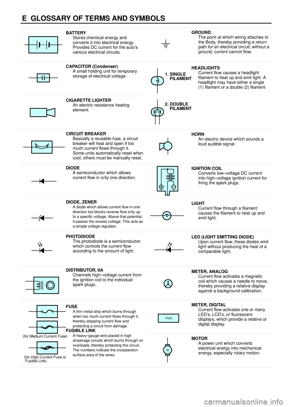
BATTERY
Stores chemical energy and
converts it into electrical energy.
Provides DC current for the auto's
various electrical circuits.GROUND
The point at which wiring attaches to
the Body, thereby providing a return
path for an electrical circuit; without a
ground, current cannot flow.
CAPACITOR (Condenser)
A small holding unit for temporary
storage of electrical voltage.HEADLIGHTS
Current flow causes a headlight
filament to heat up and emit light. A
headlight may have either a single
(1) filament or a double (2) filament
1. SINGLE
FILAMENT
CIGARETTE LIGHTER
An electric resistance heating
element.2. DOUBLE
FILAMENT
CIRCUIT BREAKER
Basically a reusable fuse, a circuit
breaker will heat and open if too
much current flows through it.
Some units automatically reset when
cool, others must be manually reset.HORN
An electric device which sounds a
loud audible signal.
DIODE
A semiconductor which allows
current flow in only one direction.IGNITION COIL
Converts low±voltage DC current
into high±voltage ignition current for
firing the spark plugs.
DIODE, ZENERA diode which allows current flow in one
direction but blocks reverse flow only up
to a specific voltage. Above that potential,
it passes the excess voltage. This acts as
a simple voltage regulator.LIGHT
Current flow through a filament
causes the filament to heat up and
emit light.
PHOTODIODE
The photodiode is a semiconductor
which controls the current flow
according to the amount of light.LED (LIGHT EMITTING DIODE)
Upon current flow, these diodes emit
light without producing the heat of a
comparable light.
DISTRIBUTOR, IIA
Channels high±voltage current from
the ignition coil to the individual
spark plugs.METER, ANALOG
Current flow activates a magnetic
coil which causes a needle to move,
thereby providing a relative display
against a background calibration.
FUSEA thin metal strip which burns through
when too much current flows through it,
thereby stopping current flow and
protecting a circuit from damage.
FUSIBLE LINK
METER, DIGITAL
Current flow activates one or many
LED's, LCD's, or fluorescent
displays, which provide a relative or
digital display.
FUEL
FUSIBLE LINK
A heavy±gauge wire placed in high
amperage circuits which burns through on
overloads, thereby protecting the circuit.
The numbers indicate the crosssection
surface area of the wires.(for Medium Current Fuse)
(for High Current Fuse or
Fusible Link)MOTOR
A power unit which converts
electrical energy into mechanical
energy, especially rotary motion.
M