1999 TOYOTA CAMRY turn signal
[x] Cancel search: turn signalPage 4107 of 4592

DOOR LOCK CONTROL
Current always flows to TERMINAL (A) 13 of the integration relay through the DOOR fuse.
When the ignition SW is turned on, the current flowing through the GAUGE Fuse flows to TERMINAL 7 of the integration
relay to TERMINAL (A) 12 to the POWER relay (Coil side) to GROUND.
1. MANUAL LOCK OPERATION
When the door lock control SW or door key lock and unlock SW are operated to LOCK position, a lock signal is input to
TERMINAL (A) 1 or (A) 3 of the integration relay and causes the relay to function. Current flows from TERMINAL (A) 13 of
the relay to TERMINAL (A) 6 to TERMINAL 2 of the door lock motors to TERMINAL 3 to TERMINAL (A) 7 of the relay to
TERMINAL 10 to GROUND and the door lock motor causes the door to lock.
2. MANUAL UNLOCK OPERATION
When the door lock control SW or door key lock and unlock SW are operated to UNLOCK position, an unlock signal is input
to TERMINAL (A) 2, (A) 4 or (A) 5 of the integration relay and causes the relay to function. Current flows from TERMINAL (A)
13 of the relay to TERMINAL (A) 7 to TERMINAL 3 of the door lock motors to TERMINAL 2 to TERMINAL (A) 6 of the relay
to TERMINAL 10 to GROUND and door lock motors causes door to unlock.
3. DOUBLE OPERATION UNLOCK OPERATION
When the door key lock and unlock SW front LH is turned to the unlock side, only the driver's door to unlock. Turning the
door key lock and unlock SW front LH to the unlock side causes a signal to be input to TERMINAL (A) 4 of the relay, and if
the signal is input again within 3 seconds by turning the SW to the unlock side again, current flows from TERMINAL (A) 7 of
the integration relay to TERMINAL 3 of the door lock motors to TERMINAL 2 of the door lock motors to TERMINAL (A) 6 of
the relay to TERMINAL 10 to GROUND, causing the door lock motors to operate and unlock the doors.
4. IGNITION KEY REMINDER OPERATION
When the door is locked using the door lock knob with the ignition key remaining in the key cylinder and door opened, it is
automatically unlocked. Additionally, if lock operation is made by the door lock control SW or door key lock and unlock, after
the lock operation is completed, the doors are unlocked automatically.
I12 (A) INTEGRATION RELAY
10±GROUND : Always continuity
6±GROUND : Continuity with the front LH door open
7±GROUND : Approx. 12 volts with the ignition SW at ON or ST position
(A)13±GROUND : Always approx. 12 volts
(A) 6±GROUND : Approx. 12 volts 0.2 seconds with following operation
* Door lock control SW locked
* Locking the front LH, RH door cylinder with key
(A) 1±GROUND : Continuity with the door lock control SW locked
(A) 8±GROUND : Continuity with the front RH door open
(A) 2±GROUND : Continuity with the door lock control SW unlocked
(A) 5±GROUND : Continuity with the front RH door lock cylinder unlocked with key
(A) 4±GROUND : Continuity with the front LH door lock cylinder unlocked with key
(A) 3±GROUND : Continuity with the front LH, RH door lock cylinder locked with key
(A) 7±GROUND : Approx. 12 volts 0.2 seconds with following operation
* Door lock control SW unlocked
* Door lock control SW locked with the ignition key in cylinder and the front LH door open
(Ignition key reminder function)
* Door lock knob locked with the ignition key in cylinder and the front LH door open
(Ignition key reminder function)
* Unlocking the front LH, RH door cylinder with key
D7, D8 DOOR COURTESY SW FRONT LH,RH
1±GROUND : Closed with the each door open
D11, D12 DOOR KEY LOCK AND UNLOCK SW FRONT LH,RH
1±2 : Closed with the door lock cylinder locked with key
1±3 : Closed with the door lock cylinder unlocked with key
D14, D15 DOOR LOCK MOTOR AND DOOR UNLOCK DETECTION SW FRONT LH,RH
1±4 : Closed with the door lock knob UNLOCK position
U1 UNLOCK WARNING SW
1±2 : Closed with the ignition key in cylinder
SYSTEM OUTLINE
SERVICE HINTS
Page 4112 of 4592

The electronically controlled transmission, however, electrically controls the line pressure and lock±up pressure etc., through
the solenoid valve. Engine control module controls of the solenoid valve based on the input signals from each sensor which
makes smooth driving possible by shift selection for each gear which is most appropriate to the driving conditions at that
time.
1. GEAR SHIFT OPERATION
During driving, the engine control module selects the shift for each gear which is most appropriate to the driving conditions,
based on input signals from the engine coolant temp. sensor to TERMINAL THW of the engine control module, and also the
input signals to TERMINAL SPD of the engine control module from the vehicle speed sensor devoted to the electronically
controlled transmission. Current is then output to the electronically controlled transmission solenoid. When shifting to 1st
gear, current flows from TERMINAL S1 of the engine control module to TERMINAL (B) 3 of the solenoid to GROUND, and
continuity to the No.1 solenoid causes the shift.
For 2nd gear, current flows from TERMINAL S1 of the engine control module to TERMINAL (B) 3 of the solenoid to
GROUND, and from TERMINAL S2 of the engine control module to TERMINAL (B) 1 of the solenoid to GROUND, and
continuity to solenoids No.1 and No.2 causes the shift.
For 3rd gear, there is no continuity to No.1 solenoid, only to No.2, causing the shift.
Shifting into 4th gear (Overdrive) takes place when there is no continuity to either No.1 or No.2 solenoid.
2. LOCK±UP OPERATION
When the engine control module judges from each signal that lock±up operation conditions have been met, current flows
from TERMINAL SL of the engine control module to TERMINAL (A) 1 of the electronically controlled transmission solenoid to
GROUND, causing continuity to the lock±up solenoid and causing lock±up operation.
3. STOP LIGHT SW CIRCUIT
If the brake pedal is depressed (Stop light SW on) when driving in lock±up condition, a signal is input to TERMINAL STP of
the engine control module, the engine control module operates and continuity to the lock±up solenoid is cut.
4. OVERDRIVE CIRCUIT
*O/D main SW on
When the O/D main SW is turned on (O/D off indicator light turns off), a signal is input into TERMINAL OD2 of the engine
control module and engine control module operation causes gear shift when the conditions for overdrive are met.
*O/D main SW off
When the O/D main SW is turned to off, the current through the O/D off indicator light flows through the O/D main SW to
GROUND, causing the indicator light to light up. At the same time, a signal is input into TERMINAL OD2 of the engine
control module and engine control module operation prevents shift into overdrive.
E4 (A), E5 (B), E6 (C) ENGINE CONTROL MODULE
S1, S2±E1 :9.0±14.0 volts with the solenoid on
0±1.5 volts with the solenoid off
L±E1 :7.5±14.0 volts with the shift lever at L position
2±E1 :7.5±14.0 volts with the shift lever at 2 position
R±E1 :7.5±14.0 volts with the shift lever at R position
STP±E1 :9.0±14.0 volts with the brake pedal depressed
THW±E2 :0.2±1.0 volts with the ignition SW on and coolant temp. 80°C (176°F)
VTA±E2 :0.3±0.8 volts with the throttle valve fully closed
3.2±4.9 volts with the throttle valve fully opened
VC±E2 :4.5±5.5 volts
OD2±E1 :9.0±14.0 volts with the O/D main SW turned on
0±3.0 volts with the O/D main SW turned off
+B±E1 :9.0±14.0 volts
O2 O/D MAIN SW
2±4 : Closed with the O/D main SW off, open with the O/D main SW on
SYSTEM OUTLINE
SERVICE HINTS
Page 4121 of 4592
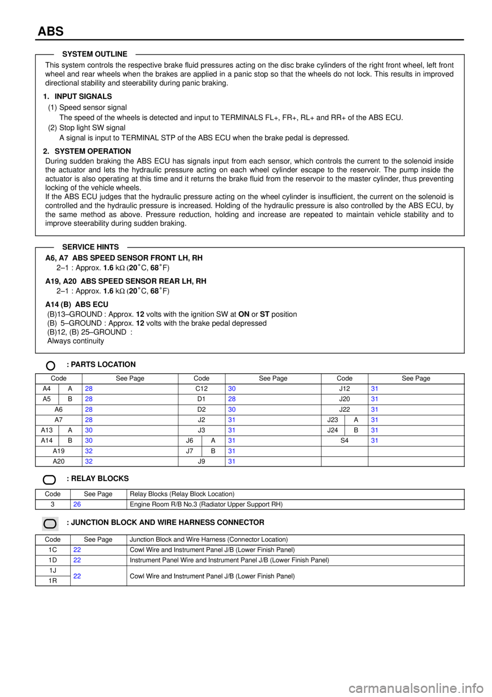
ABS
This system controls the respective brake fluid pressures acting on the disc brake cylinders of the right front wheel, left front
wheel and rear wheels when the brakes are applied in a panic stop so that the wheels do not lock. This results in improved
directional stability and steerability during panic braking.
1. INPUT SIGNALS
(1) Speed sensor signal
The speed of the wheels is detected and input to TERMINALS FL+, FR+, RL+ and RR+ of the ABS ECU.
(2) Stop light SW signal
A signal is input to TERMINAL STP of the ABS ECU when the brake pedal is depressed.
2. SYSTEM OPERATION
During sudden braking the ABS ECU has signals input from each sensor, which controls the current to the solenoid inside
the actuator and lets the hydraulic pressure acting on each wheel cylinder escape to the reservoir. The pump inside the
actuator is also operating at this time and it returns the brake fluid from the reservoir to the master cylinder, thus preventing
locking of the vehicle wheels.
If the ABS ECU judges that the hydraulic pressure acting on the wheel cylinder is insufficient, the current on the solenoid is
controlled and the hydraulic pressure is increased. Holding of the hydraulic pressure is also controlled by the ABS ECU, by
the same method as above. Pressure reduction, holding and increase are repeated to maintain vehicle stability and to
improve steerability during sudden braking.
A6, A7 ABS SPEED SENSOR FRONT LH, RH
2±1 : Approx. 1.6 kW (20°C, 68°F)
A19, A20 ABS SPEED SENSOR REAR LH, RH
2±1 : Approx. 1.6 kW (20°C, 68°F)
A14 (B) ABS ECU
(B)13±GROUND : Approx. 12 volts with the ignition SW at ON or ST position
(B) 5±GROUND : Approx. 12 volts with the brake pedal depressed
(B)12, (B) 25±GROUND :
Always continuity
: PARTS LOCATION
CodeSee PageCodeSee PageCodeSee Page
A4A28C1230J1231
A5B28D128J2031
A628D230J2231
A728J231J23A31
A13A30J331J24B31
A14B30J6A31S431
A1932J7B31
A2032J931
: RELAY BLOCKS
CodeSee PageRelay Blocks (Relay Block Location)
326Engine Room R/B No.3 (Radiator Upper Support RH)
������ ���: JUNCTION BLOCK AND WIRE HARNESS CONNECTOR
CodeSee PageJunction Block and Wire Harness (Connector Location)
1C22Cowl Wire and Instrument Panel J/B (Lower Finish Panel)
1D22Instrument Panel Wire and Instrument Panel J/B (Lower Finish Panel)
1J22Cowl Wire and Instrument Panel J/B (Lower Finish Panel)1R22Cowl Wire and Instrument Panel J/B (Lower Finish Panel)
SYSTEM OUTLINE
SERVICE HINTS
Page 4130 of 4592
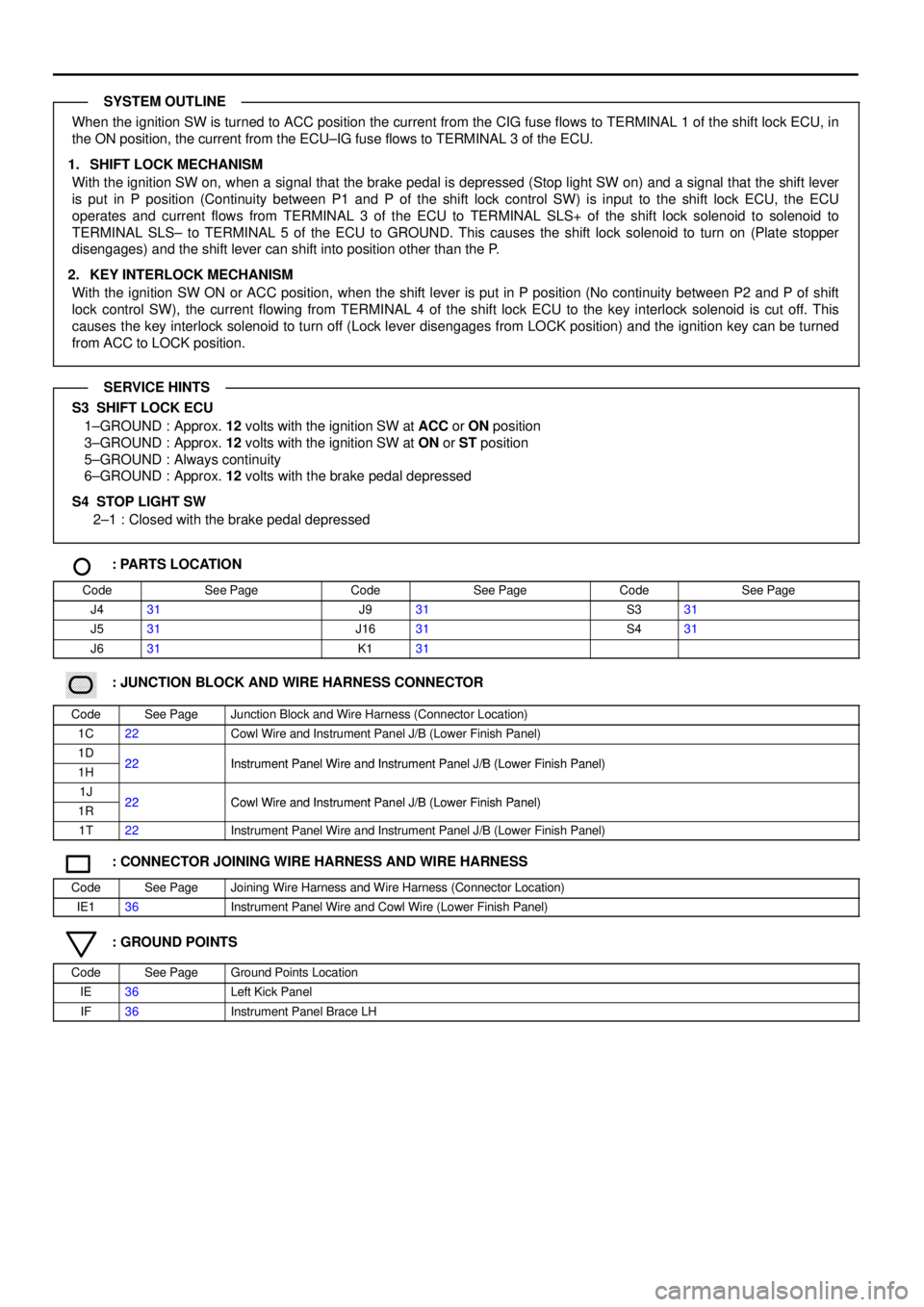
When the ignition SW is turned to ACC position the current from the CIG fuse flows to TERMINAL 1 of the shift lock ECU, in
the ON position, the current from the ECU±IG fuse flows to TERMINAL 3 of the ECU.
1. SHIFT LOCK MECHANISM
With the ignition SW on, when a signal that the brake pedal is depressed (Stop light SW on) and a signal that the shift lever
is put in P position (Continuity between P1 and P of the shift lock control SW) is input to the shift lock ECU, the ECU
operates and current flows from TERMINAL 3 of the ECU to TERMINAL SLS+ of the shift lock solenoid to solenoid to
TERMINAL SLS± to TERMINAL 5 of the ECU to GROUND. This causes the shift lock solenoid to turn on (Plate stopper
disengages) and the shift lever can shift into position other than the P.
2. KEY INTERLOCK MECHANISM
With the ignition SW ON or ACC position, when the shift lever is put in P position (No continuity between P2 and P of shift
lock control SW), the current flowing from TERMINAL 4 of the shift lock ECU to the key interlock solenoid is cut off. This
causes the key interlock solenoid to turn off (Lock lever disengages from LOCK position) and the ignition key can be turned
from ACC to LOCK position.
S3 SHIFT LOCK ECU
1±GROUND : Approx. 12 volts with the ignition SW at ACC or ON position
3±GROUND : Approx. 12 volts with the ignition SW at ON or ST position
5±GROUND : Always continuity
6±GROUND : Approx. 12 volts with the brake pedal depressed
S4 STOP LIGHT SW
2±1 : Closed with the brake pedal depressed
: PARTS LOCATION
CodeSee PageCodeSee PageCodeSee Page
J431J931S331
J531J1631S431
J631K131
������ ���: JUNCTION BLOCK AND WIRE HARNESS CONNECTOR
CodeSee PageJunction Block and Wire Harness (Connector Location)
1C22Cowl Wire and Instrument Panel J/B (Lower Finish Panel)
1D22Instrument Panel Wire and Instrument Panel J/B (Lower Finish Panel)1H22Instrument Panel Wire and Instrument Panel J/B (Lower Finish Panel)
1J22Cowl Wire and Instrument Panel J/B (Lower Finish Panel)1R22Cowl Wire and Instrument Panel J/B (Lower Finish Panel)
1T22Instrument Panel Wire and Instrument Panel J/B (Lower Finish Panel)
: CONNECTOR JOINING WIRE HARNESS AND WIRE HARNESS
CodeSee PageJoining Wire Harness and Wire Harness (Connector Location)
IE136Instrument Panel Wire and Cowl Wire (Lower Finish Panel)
: GROUND POINTS
CodeSee PageGround Points Location
IE36Left Kick Panel
IF36Instrument Panel Brace LH
SYSTEM OUTLINE
SERVICE HINTS
Page 4136 of 4592
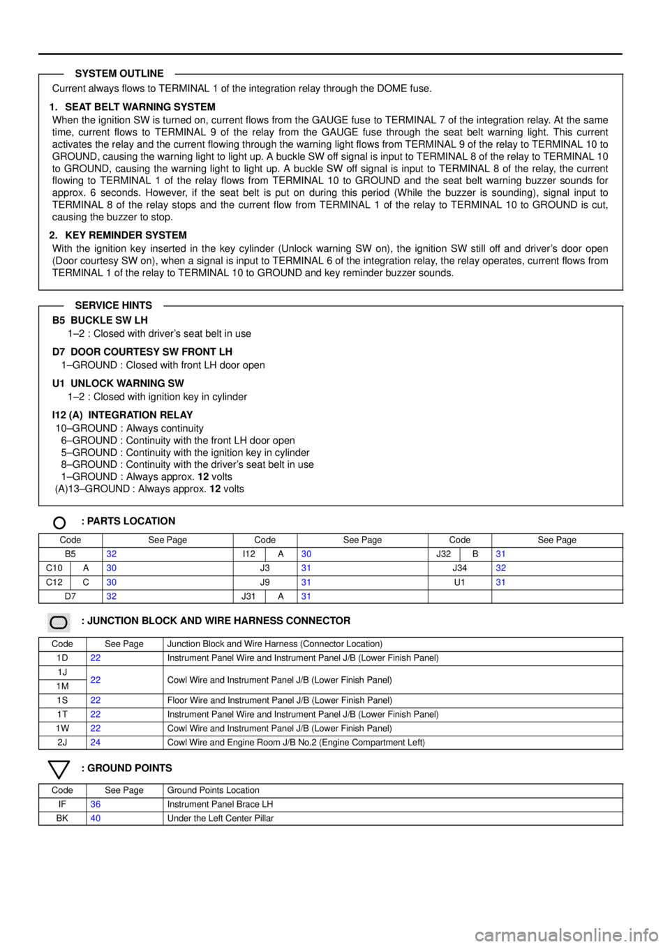
Current always flows to TERMINAL 1 of the integration relay through the DOME fuse.
1. SEAT BELT WARNING SYSTEM
When the ignition SW is turned on, current flows from the GAUGE fuse to TERMINAL 7 of the integration relay. At the same
time, current flows to TERMINAL 9 of the relay from the GAUGE fuse through the seat belt warning light. This current
activates the relay and the current flowing through the warning light flows from TERMINAL 9 of the relay to TERMINAL 10 to
GROUND, causing the warning light to light up. A buckle SW off signal is input to TERMINAL 8 of the relay to TERMINAL 10
to GROUND, causing the warning light to light up. A buckle SW off signal is input to TERMINAL 8 of the relay, the current
flowing to TERMINAL 1 of the relay flows from TERMINAL 10 to GROUND and the seat belt warning buzzer sounds for
approx. 6 seconds. However, if the seat belt is put on during this period (While the buzzer is sounding), signal input to
TERMINAL 8 of the relay stops and the current flow from TERMINAL 1 of the relay to TERMINAL 10 to GROUND is cut,
causing the buzzer to stop.
2. KEY REMINDER SYSTEM
With the ignition key inserted in the key cylinder (Unlock warning SW on), the ignition SW still off and driver's door open
(Door courtesy SW on), when a signal is input to TERMINAL 6 of the integration relay, the relay operates, current flows from
TERMINAL 1 of the relay to TERMINAL 10 to GROUND and key reminder buzzer sounds.
B5 BUCKLE SW LH
1±2 : Closed with driver's seat belt in use
D7 DOOR COURTESY SW FRONT LH
1±GROUND : Closed with front LH door open
U1 UNLOCK WARNING SW
1±2 : Closed with ignition key in cylinder
I12 (A) INTEGRATION RELAY
10±GROUND : Always continuity
6±GROUND : Continuity with the front LH door open
5±GROUND : Continuity with the ignition key in cylinder
8±GROUND : Continuity with the driver's seat belt in use
1±GROUND : Always approx. 12 volts
(A)13±GROUND : Always approx. 12 volts
: PARTS LOCATION
CodeSee PageCodeSee PageCodeSee Page
B532I12A30J32B31
C10A30J331J3432
C12C30J931U131
D732J31A31
������ ���: JUNCTION BLOCK AND WIRE HARNESS CONNECTOR
CodeSee PageJunction Block and Wire Harness (Connector Location)
1D22Instrument Panel Wire and Instrument Panel J/B (Lower Finish Panel)
1J22Cowl Wire and Instrument Panel J/B (Lower Finish Panel)1M22Cowl Wire and Instrument Panel J/B (Lower Finish Panel)
1S22Floor Wire and Instrument Panel J/B (Lower Finish Panel)
1T22Instrument Panel Wire and Instrument Panel J/B (Lower Finish Panel)
1W22Cowl Wire and Instrument Panel J/B (Lower Finish Panel)
2J24Cowl Wire and Engine Room J/B No.2 (Engine Compartment Left)
: GROUND POINTS
CodeSee PageGround Points Location
IF36Instrument Panel Brace LH
BK40Under the Left Center Pillar
SYSTEM OUTLINE
SERVICE HINTS
Page 4147 of 4592
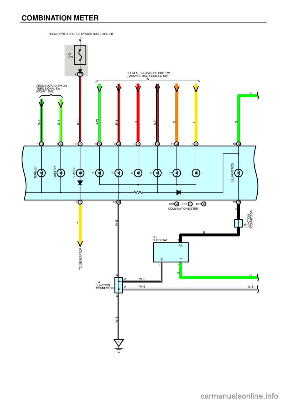
COMBINATION METER
5A
IGN
1T 8 FROM POWER SOURCE SYSTEM (
SEE PAGE 44)
B 1C1A13 A9A8A10 A7A6C13
B 4B16C 12
IEW±B
W±BG
W±BG
B
G± B
G± Y
B±R
G± W
R±B
R
B±R
O
Y
G Y
W± B W± B
G
B
A2
A31
A
AETILL FROM HAZARD SW OR
TURN SIGNAL SW
[COMB. SW]FROM A/T INDICATOR LIGHT SW
[PARK/NEUTRAL POSITION SW]
TO GENERATORTURN LH
TURN RH
CHARGE
P
R
N
D
2
L
ILLUMINATION
RHEOSTAT R 6
JUNCTION
CONNECTOR J 4C10
COMBINATION METERB A, C11 C, C12 A 11
D D
JUNCTION
CONNECTOR J16
Page 4158 of 4592
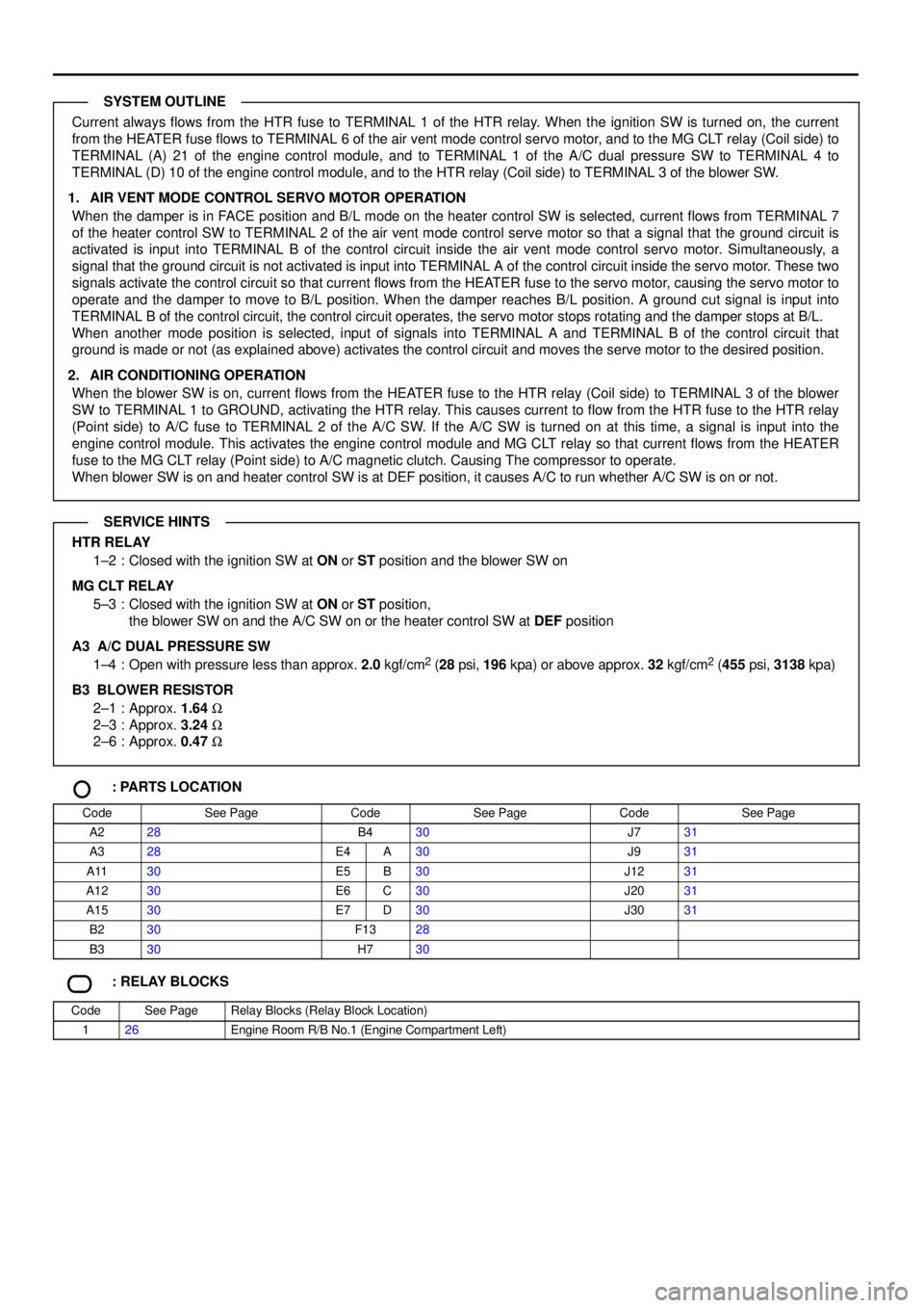
Current always flows from the HTR fuse to TERMINAL 1 of the HTR relay. When the ignition SW is turned on, the current
from the HEATER fuse flows to TERMINAL 6 of the air vent mode control servo motor, and to the MG CLT relay (Coil side) to
TERMINAL (A) 21 of the engine control module, and to TERMINAL 1 of the A/C dual pressure SW to TERMINAL 4 to
TERMINAL (D) 10 of the engine control module, and to the HTR relay (Coil side) to TERMINAL 3 of the blower SW.
1. AIR VENT MODE CONTROL SERVO MOTOR OPERATION
When the damper is in FACE position and B/L mode on the heater control SW is selected, current flows from TERMINAL 7
of the heater control SW to TERMINAL 2 of the air vent mode control serve motor so that a signal that the ground circuit is
activated is input into TERMINAL B of the control circuit inside the air vent mode control servo motor. Simultaneously, a
signal that the ground circuit is not activated is input into TERMINAL A of the control circuit inside the servo motor. These two
signals activate the control circuit so that current flows from the HEATER fuse to the servo motor, causing the servo motor to
operate and the damper to move to B/L position. When the damper reaches B/L position. A ground cut signal is input into
TERMINAL B of the control circuit, the control circuit operates, the servo motor stops rotating and the damper stops at B/L.
When another mode position is selected, input of signals into TERMINAL A and TERMINAL B of the control circuit that
ground is made or not (as explained above) activates the control circuit and moves the serve motor to the desired position.
2. AIR CONDITIONING OPERATION
When the blower SW is on, current flows from the HEATER fuse to the HTR relay (Coil side) to TERMINAL 3 of the blower
SW to TERMINAL 1 to GROUND, activating the HTR relay. This causes current to flow from the HTR fuse to the HTR relay
(Point side) to A/C fuse to TERMINAL 2 of the A/C SW. If the A/C SW is turned on at this time, a signal is input into the
engine control module. This activates the engine control module and MG CLT relay so that current flows from the HEATER
fuse to the MG CLT relay (Point side) to A/C magnetic clutch. Causing The compressor to operate.
When blower SW is on and heater control SW is at DEF position, it causes A/C to run whether A/C SW is on or not.
HTR RELAY
1±2 : Closed with the ignition SW at ON or ST position and the blower SW on
MG CLT RELAY
5±3 : Closed with the ignition SW at ON or ST position,
the blower SW on and the A/C SW on or the heater control SW at DEF position
A3 A/C DUAL PRESSURE SW
1±4 : Open with pressure less than approx. 2.0 kgf/cm
2 (28 psi, 196 kpa) or above approx. 32 kgf/cm2 (455 psi, 3138 kpa)
B3
BLOWER RESISTOR
2±1 : Approx. 1.64 W
2±3 : Approx. 3.24 W
2±6 : Approx. 0.47 W
: PARTS LOCATION
CodeSee PageCodeSee PageCodeSee Page
A228B430J731
A328E4A30J931
A1130E5B30J1231
A1230E6C30J2031
A1530E7D30J3031
B230F1328
B330H730
: RELAY BLOCKS
CodeSee PageRelay Blocks (Relay Block Location)
126Engine Room R/B No.1 (Engine Compartment Left)
SYSTEM OUTLINE
SERVICE HINTS
Page 4161 of 4592
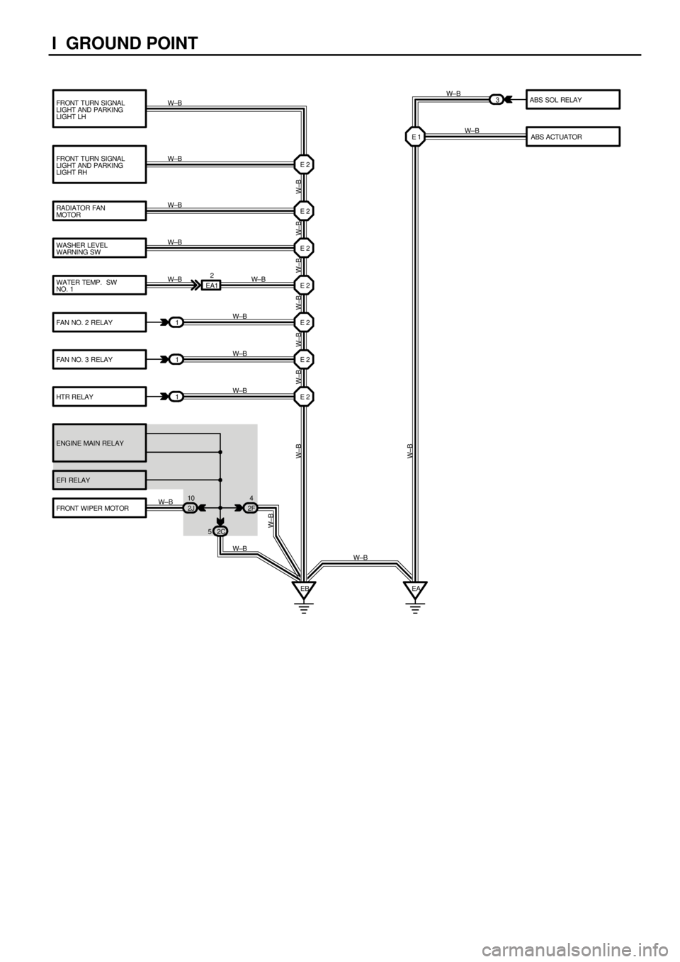
I GROUND POINT
FRONT TURN SIGNAL
LIGHT AND PARKING
LIGHT LH
FRONT TURN SIGNAL
LIGHT AND PARKING
LIGHT RH
RADIATOR FAN
MOTOR
WASHER LEVEL
WARNING SW
WATER TEMP. SW
NO. 1
FAN NO. 2 RELAYABS SOL RELAY
FAN NO. 3 RELAY
HTR RELAY
ENGINE MAIN RELAY
EFI RELAY
FRONT WIPER MOTORABS ACTUATOR
1
1
1EA12
E 2 E 2
E 2
E 2
E 2
E 2
E 2
2J 10
2F4
2C 5
EB3
E 1
EA W±B W±B W±B W±B W±B
W± B
W±B
W±B
W±BW±B
W±B W± B W±B W±B W± B W±B W± B
W±B
W±B
W± B
W±B
W±B
W±B