1999 TOYOTA CAMRY turn signal
[x] Cancel search: turn signalPage 4028 of 4592
E
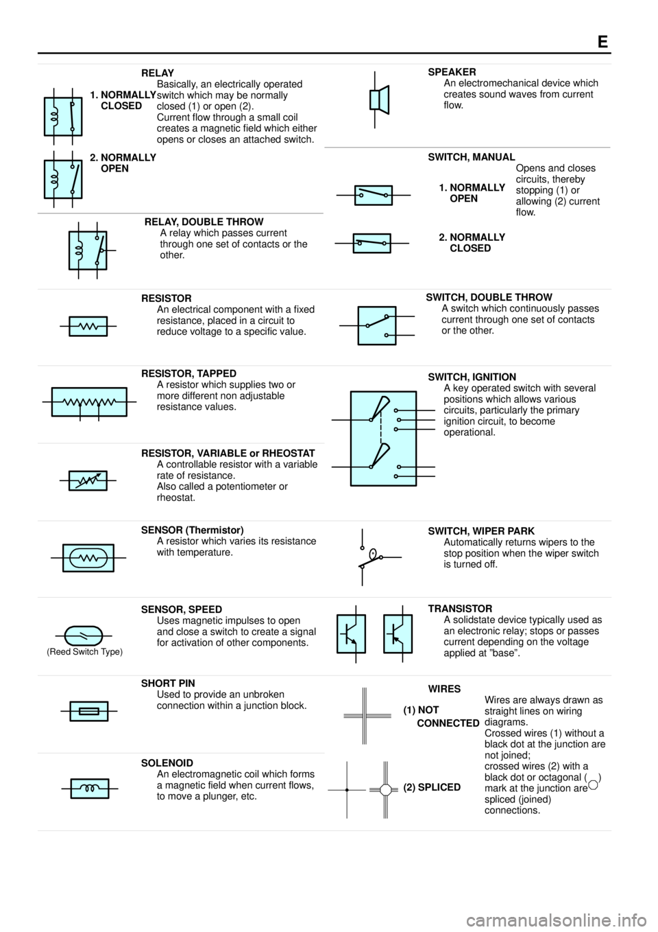
RELAY
Basically, an electrically operated
switch which may be normally
closed (1) or open (2).
Current flow through a small coil
creates a magnetic field which either
opens or closes an attached switch.
1. NORMALLY
CLOSED
2. NORMALLY
OPEN
SWITCH, MANUAL
Opens and closes
iitth b
SPEAKER
An electromechanical device which
creates sound waves from current
flow.
RELAY, DOUBLE THROW
A relay which passes current
through one set of contacts or the
other.
circuits, thereby
stopping (1) or
allowing (2) current
flow.1. NORMALLY
OPEN
2. NORMALLY
CLOSED
RESISTOR
An electrical component with a fixed
resistance, placed in a circuit to
reduce voltage to a specific value.SWITCH, DOUBLE THROW
A switch which continuously passes
current through one set of contacts
or the other.
RESISTOR, TAPPED
A resistor which supplies two or
more different non adjustable
resistance values.SWITCH, IGNITION
A key operated switch with several
positions which allows various
circuits, particularly the primary
ignition circuit, to become
operational.
RESISTOR, VARIABLE or RHEOSTAT
A controllable resistor with a variable
rate of resistance.
Also called a potentiometer or
rheostat.
SENSOR (Thermistor)
A resistor which varies its resistance
with temperature.SWITCH, WIPER PARK
Automatically returns wipers to the
stop position when the wiper switch
is turned off.
(Reed Switch Type)
SENSOR, SPEED
Uses magnetic impulses to open
and close a switch to create a signal
for activation of other components.TRANSISTOR
A solidstate device typically used as
an electronic relay; stops or passes
current depending on the voltage
applied at ºbaseº.
SHORT PIN
Used to provide an unbroken
connection within a junction block.WIRES
Wires are always drawn as
straight lines on wiring
diagrams.
Crossed wires (1) without a
black dot at the junction are
tj i d
(1) NOT
CONNECTED
SOLENOID
An electromagnetic coil which forms
a magnetic field when current flows,
to move a plunger, etc.
j
not joined;
crossed wires (2) with a
black dot or octagonal ( )
mark at the junction are
spliced (joined)
connections.
(2) SPLICED
Page 4037 of 4592

G ELECTRICAL WIRING ROUTING
Position of Parts in Engine Compartment
A 1 A/C Condenser Fan Motor
A 2 A/C Magnetic Clutch and Lock Sensor
A 3 A/C Triple Pressure SW
(A/C Dual and Single Pressure SW)
A 4 ABS Actuator
A 5 ABS Actuator
A 6 ABS Speed Sensor Front LH
A 7 ABS Speed Sensor Front RH
A 8 Air Fuel Ratio Sensor
A 9 Airbag Sensor Front LH
A 10 Airbag Sensor Front RH
B 1 Brake Fluid Level Warning SW
C 1 Camshaft Position Sensor
C 2 Crankshaft Position Sensor
C 3 Cruise Control Actuator
D 1 Data Link Connector 1
E 1 Electronically Controlled Transmission Solenoid
E 2 Electronically Controlled Transmission Solenoid
E 3 Engine Coolant Temp. SensorF 1 Front Turn Signal Light and Parking Light LH
F 2 Front Turn Signal Light and Parking Light RH
F 3 Front Wiper Motor
F 4 Fuel Pressure Sensor (Delivery Pipe)
F 5 Fuel Pressure Sensor (Fuel Pipe)
F 6 Fuel Shutoff Valve (Delivery Pipe)
F 7 Fuel Shutoff Valve (Fuel Pressure Regulator)
F 8 Fuel Temp. Sensor (Delivery Pipe)
F 9 Fusible Link Block
F 10 Fusible Link Block
F 11 Fusible Link Block
F 12 Fusible Link Block
F 13 Fusible Link Block
F 14 Fusible Link Block
G 1 Generator
G 2 Generator
H 1 Headlight LH
H 2 Headlight RH
H 3 Horn (High)
H 4 Horn (Low)
Page 4040 of 4592

G
Position of Parts in Instrument Panel
J 1 Junction Connector
J 2 Junction Connector
J 3 Junction Connector
J 4 Junction Connector
J 5 Junction Connector
J 6 Junction Connector
J 7 Junction Connector
J 8 Junction Connector
J 9 Junction Connector
J 10 Junction Connector
J 11 Junction Connector
J 12 Junction Connector
J 13 Junction Connector
J 14 Junction Connector
J 15 Junction Connector
J 16 Junction Connector
J 17 Junction Connector
J 18 Junction Connector
J 19 Junction Connector
J 20 Junction Connector
J 21 Junction Connector
J 22 Junction Connector
J 23 Junction Connector
J 24 Junction Connector
J 25 Junction Connector
J 26 Junction ConnectorJ 27 Junction Connector
J 28 Junction Connector
J 29 Junction Connector
J 30 Junction Connector
J 31 Junction Connector
J 32 Junction Connector
K 1 Key Interlock Solenoid
O 2 O/D Main SW and A/T Shift Lever Illumination
P 3 Parking Brake SW
P 4 Power Outlet
R 2 Radio and Player
R 3 Radio and Player
R 4 Rear Window Defogger SW
R 5 Remote Control Mirror SW
R 6 Rheostat
S 3 Shift Lock ECU
S 4 Stop Light SW
T 2 Turn Signal Flasher
U 1 Unlock Warning SW
Page 4068 of 4592

This system utilizes an engine control module and maintains overall control of the engine, transmission and so on. An outline
of the engine control is explained here.
1. INPUT SIGNALS
(1) Engine coolant temp. signal circuit
The engine coolant temp. sensor detects the engine coolant temp. and has a built±in thermistor with a resistance which
varies according to the engine coolant temp. thus the engine coolant temp. is input in the form of a control signal into
TERMINAL THW of the engine control module.
(2) Intake air temp. signal circuit
The intake air temp. sensor detects the intake air temp. , which is input as a control signal into TERMINAL THA of the
engine control module.
(3) Oxygen sensor signal circuit
The oxygen density in the exhaust gases is detected and input as a control signal into TERMINAL OX2 of the engine
control module.
(4) RPM signal circuit
Camshaft position and crankshaft position are detected by the camshaft position sensor and crankshaft position sensor.
Camshaft position is input as a control signal to TERMINAL G of the engine control module, and engine RPM is input
into TERMINAL NE.
(5) Throttle signal circuit
The throttle position sensor detects the throttle valve opening angle, which is input as a control signal into TERMINAL
VTA of the engine control module.
(6) Vehicle speed signal circuit
The vehicle speed sensor, installed inside the transmission, detects the vehicle speed and inputs a control signal into
TERMINAL SPD of the engine control module.
(7) Park/Neutral position SW signal circuit
The Park/Neutral position SW detects whether the shift position are in neutral, parking or not, and inputs a control signal
into TERMINAL STA of the engine control module.
(8) A/C SW signal circuit
The A/C amplifier is built in the engine control module. The signal from the A/C SW is input into TERMINAL A/CS of the
engine control module.
(9) Battery signal circuit
Voltage is constantly applied to TERMINAL BATT of the engine control module. When the ignition SW is turned on, the
voltage for engine control module start±up power supply is applied to TERMINAL +B of engine control module via EFI
relay.
(10) Intake air volume signal circuit
Intake air volume is detected by the manifold absolute pressure sensor (for manifold pressure) and is input as a control
signal into TERMINAL PIM of the engine control module.
(11) Starter signal circuit
To confirm whether the engine is cranking, the voltage applied to the starter motor during cranking is detected and the
signal is input into TERMINAL NSW of the engine control module as a control signal.
(12) Electrical load signal circuit
The signal when systems such as the rear window defogger, headlights, etc. Which cause a high electrical burden are
on is input to TERMINAL ELS as a control signal.
(13) Air fuel ratio signal circuit
The air fuel ratio is detected and input as a control signal into TERMINAL AF+ of the engine control module.
SYSTEM OUTLINE
Page 4076 of 4592
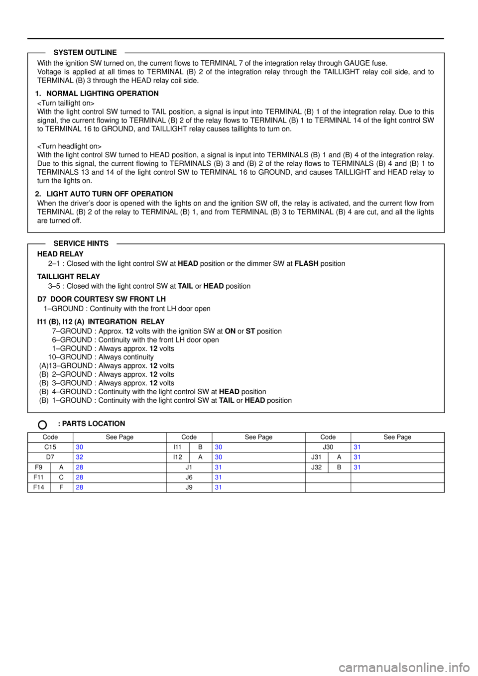
With the ignition SW turned on, the current flows to TERMINAL 7 of the integration relay through GAUGE fuse.
Voltage is applied at all times to TERMINAL (B) 2 of the integration relay through the TAILLIGHT relay coil side, and to
TERMINAL (B) 3 through the HEAD relay coil side.
1. NORMAL LIGHTING OPERATION
With the light control SW turned to TAIL position, a signal is input into TERMINAL (B) 1 of the integration relay. Due to this
signal, the current flowing to TERMINAL (B) 2 of the relay flows to TERMINAL (B) 1 to TERMINAL 14 of the light control SW
to TERMINAL 16 to GROUND, and TAILLIGHT relay causes taillights to turn on.
With the light control SW turned to HEAD position, a signal is input into TERMINALS (B) 1 and (B) 4 of the integration relay.
Due to this signal, the current flowing to TERMINALS (B) 3 and (B) 2 of the relay flows to TERMINALS (B) 4 and (B) 1 to
TERMINALS 13 and 14 of the light control SW to TERMINAL 16 to GROUND, and causes TAILLIGHT and HEAD relay to
turn the lights on.
2. LIGHT AUTO TURN OFF OPERATION
When the driver's door is opened with the lights on and the ignition SW off, the relay is activated, and the current flow from
TERMINAL (B) 2 of the relay to TERMINAL (B) 1, and from TERMINAL (B) 3 to TERMINAL (B) 4 are cut, and all the lights
are turned off.
HEAD RELAY
2±1 : Closed with the light control SW at HEAD position or the dimmer SW at FLASH position
TAILLIGHT RELAY
3±5 : Closed with the light control SW at TAIL or HEAD position
D7 DOOR COURTESY SW FRONT LH
1±GROUND : Continuity with the front LH door open
I11 (B), I12 (A)
INTEGRATION RELAY
7±GROUND : Approx. 12 volts with the ignition SW at ON or ST position
6±GROUND : Continuity with the front LH door open
1±GROUND : Always approx. 12 volts
10±GROUND : Always continuity
(A)13±GROUND : Always approx. 12 volts
(B) 2±GROUND : Always approx. 12 volts
(B) 3±GROUND : Always approx. 12 volts
(B) 4±GROUND : Continuity with the light control SW at HEAD position
(B) 1±GROUND : Continuity with the light control SW at TAIL or HEAD position
: PARTS LOCATION
CodeSee PageCodeSee PageCodeSee Page
C1530I11B30J3031
D732I12A30J31A31
F9A28J131J32B31
F11C28J631
F14F28J931
SYSTEM OUTLINE
SERVICE HINTS
Page 4079 of 4592
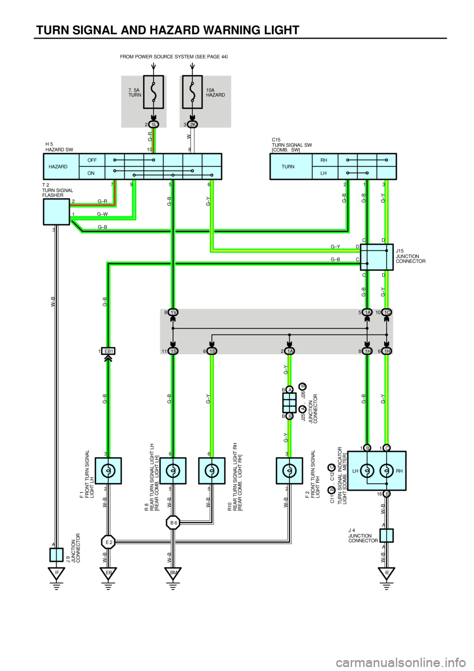
TURN SIGNAL AND HAZARD WARNING LIGHT
1L 22K3
2 3
2 3
IF EB BMIE EB1 1 37956 231
5 5
A 66
A
A10 8
2
1FROM POWER SOURCE SYSTEM (
SEE PAGE 44)
OFF
ONRH
LH TURN HAZARD10A
HAZARD 7. 5A
TURN
G± R
W
G±RG± B
G±W
G± Y W±B
G±B
G±Y
W±BG±B
G±Y
W±BW± B W±B
HAZARD SWTURN SIGNA L SW
[COMB. SW]
REAR TURN SIGNAL LIGHT LH
[REAR COMB. LIGHT LH]FRONT TURN SI GNAL
LIGHT LH
REAR TURN SIGNAL LIGHT RH
[REAR COMB. LIGHT RH]
G± B
G± Y
TURN SIGNAL
FLASHER
FRONT TURN SI GNAL
LIGHT RH F 1
R 8
R10
F 2
J 4
J 9
H 5
JUNCTION
CONNECTOR
JUNCTION
CONNECTOR
LH RH
G± B G±B
G± B
G±Y W±B
E 2B 6
W± B W± B
W± B
B 1C1
B 161C 10 1A 5 1V 8
1H 6 1H 8 1A 2 1S 11 1S6
B BA B
G±BG± Y
CDD C
D
CJUNCTION
CONNECTOR J15 T 2C15
JUNCTION
CONNECTOR
TURN SIGNAL INDICATOR
LI GHT [COMB. METER]
G±Y G±B
G±Y
G±B
C C11 B , C12B J25 A , J26
Page 4080 of 4592
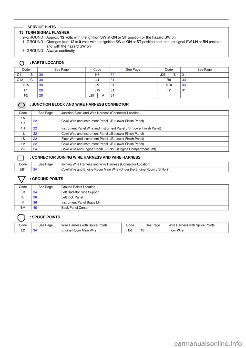
T2 TURN SIGNAL FLASHER
2±GROUND : Approx. 12 volts with the ignition SW at ON or ST position or the hazard SW on
1±GROUND : Changes from 12 to 0 volts with the ignition SW at ON or ST position and the turn signal SW LH or RH position,
and with the hazard SW on
3±GROUND : Always continuity
: PARTS LOCATION
CodeSee PageCodeSee PageCodeSee Page
C11B30H530J26B31
C12C30J431R833
C1530J931R1033
F128J1531T231
F228J25A31
������ ���: JUNCTION BLOCK AND WIRE HARNESS CONNECTOR
CodeSee PageJunction Block and Wire Harness (Connector Location)
1A22Cowl Wire and Instrument Panel J/B (Lower Finish Panel)1C22Cowl Wire and Instrument Panel J/B (Lower Finish Panel)
1H22Instrument Panel Wire and Instrument Panel J/B (Lower Finish Panel)
1L22Cowl Wire and Instrument Panel J/B (Lower Finish Panel)
1S22Floor Wire and Instrument Panel J/B (Lower Finish Panel)
1V22Cowl Wire and Instrument Panel J/B (Lower Finish Panel)
2K24Cowl Wire and Engine Room J/B No.2 (Engine Compartment Left)
: CONNECTOR JOINING WIRE HARNESS AND WIRE HARNESS
CodeSee PageJoining Wire Harness and Wire Harness (Connector Location)
EB134Cowl Wire and Engine Room Main Wire (Under the Engine Room J/B No.2)
: GROUND POINTS
CodeSee PageGround Points Location
EB34Left Radiator Side Support
IE36Left Kick Panel
IF36Instrument Panel Brace LH
BM40Back Panel Center
: SPLICE POINTS
CodeSee PageWire Harness with Splice PointsCodeSee PageWire Harness with Splice Points
E234Engine Room Main WireB640Floor Wire
SERVICE HINTS
Page 4104 of 4592
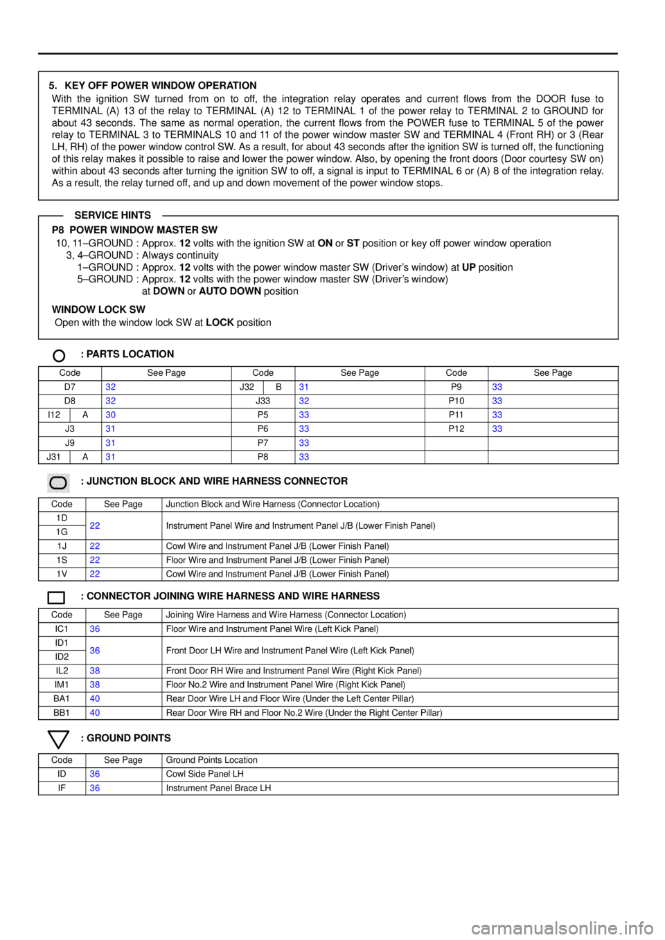
5. KEY OFF POWER WINDOW OPERATION
With the ignition SW turned from on to off, the integration relay operates and current flows from the DOOR fuse to
TERMINAL (A) 13 of the relay to TERMINAL (A) 12 to TERMINAL 1 of the power relay to TERMINAL 2 to GROUND for
about 43 seconds. The same as normal operation, the current flows from the POWER fuse to TERMINAL 5 of the power
relay to TERMINAL 3 to TERMINALS 10 and 11 of the power window master SW and TERMINAL 4 (Front RH) or 3 (Rear
LH, RH) of the power window control SW. As a result, for about 43 seconds after the ignition SW is turned off, the functioning
of this relay makes it possible to raise and lower the power window. Also, by opening the front doors (Door courtesy SW on)
within about 43 seconds after turning the ignition SW to off, a signal is input to TERMINAL 6 or (A) 8 of the integration relay.
As a result, the relay turned off, and up and down movement of the power window stops.
P8 POWER WINDOW MASTER SW
10, 11±GROUND : Approx. 12 volts with the ignition SW at ON or ST position or key off power window operation
3, 4±GROUND : Always continuity
1±GROUND : Approx. 12 volts with the power window master SW (Driver's window) at UP position
5±GROUND : Approx. 12 volts with the power window master SW (Driver's window)
at DOWN or AUTO DOWN position
WINDOW LOCK SW
Open with the window lock SW at LOCK position
: PARTS LOCATION
CodeSee PageCodeSee PageCodeSee Page
D732J32B31P933
D832J3332P1033
I12A30P533P1133
J331P633P1233
J931P733
J31A31P833
������ ���: JUNCTION BLOCK AND WIRE HARNESS CONNECTOR
CodeSee PageJunction Block and Wire Harness (Connector Location)
1D22Instrument Panel Wire and Instrument Panel J/B (Lower Finish Panel)1G22Instrument Panel Wire and Instrument Panel J/B (Lower Finish Panel)
1J22Cowl Wire and Instrument Panel J/B (Lower Finish Panel)
1S22Floor Wire and Instrument Panel J/B (Lower Finish Panel)
1V22Cowl Wire and Instrument Panel J/B (Lower Finish Panel)
: CONNECTOR JOINING WIRE HARNESS AND WIRE HARNESS
CodeSee PageJoining Wire Harness and Wire Harness (Connector Location)
IC136Floor Wire and Instrument Panel Wire (Left Kick Panel)
ID136Front Door LH Wire and Instrument Panel Wire (Left Kick Panel)ID236Front Door LH Wire and Instrument Panel Wire (Left Kick Panel)
IL238Front Door RH Wire and Instrument Panel Wire (Right Kick Panel)
IM138Floor No.2 Wire and Instrument Panel Wire (Right Kick Panel)
BA140Rear Door Wire LH and Floor Wire (Under the Left Center Pillar)
BB140Rear Door Wire RH and Floor No.2 Wire (Under the Right Center Pillar)
: GROUND POINTS
CodeSee PageGround Points Location
ID36Cowl Side Panel LH
IF36Instrument Panel Brace LH
SERVICE HINTS