Page 2925 of 4592

MA002±11
MA±2
± MAINTENANCEINSIDE VEHICLE
45 Author�: Date�:
INSIDE VEHICLE
GENERAL MAINTENANCE
These are maintenance and inspection items which are considered to be the owner's responsibility.
They can be done by the owner or they can have them done at a service shop.
These items include those which should be checked on a daily basis, those which, in most cases, do not
require (special) tools and those which are considered to be reasonable for the owner to do.
Items and procedures for general maintenance are as follows.
1. GENERAL NOTES
�Maintenance items may vary from country to country. Check the owner's manual supplement in which
the maintenance schedule is shown.
�Every service item in the periodic maintenance schedule must be performed.
�Periodic maintenance service must be performed according to whichever interval in the periodic main-
tenance schedule occurs first, the odometer reading (miles) or the time interval (months).
�Maintenance service after the last period should be performed at the same interval as before unless
otherwise noted.
�Failure to do even one item an cause the engine to run poorly and increase exhaust emissions.
2. LIGHTS
(a) Check that the headlights, stop lights, taillights, turn signal lights, and other lights are all working.
(b) Check the headlight aim.
3. WARNING LIGHTS AND BUZZERS
Check that all warning lights and buzzers function properly.
4. HORN
Check that it is working.
5. WINDSHIELD GLASS
Check for scratches, pits or abrasions.
6. WINDSHIELD WIPER AND WASHER
(a) Check operation of the wipers and washer.
(b) Check that the wipers do not streak.
7. WINDSHIELD DEFROSTER
Check that air comes out from the defroster outlet when operating the heater or air conditioner.
8. REAR VIEW MIRROR
Check that it is mounted securely.
9. SUN VISORS
Check that they move freely and are mounted securely.
10. STEERING WHEEL
Check that it has the specified freeplay. Be alert for changes in steering condition, such as hard steering,
excessive freeplay or strange noises.
11. SEATS
(a) Check that the seat adjusters operate smoothly.
(b) Check that all latches lock securely in any position.
(c) Check that the head restraints move up and down smoothly and that the locks hold securely in any
latch position.
(d) For fold±down seat backs, check that the latches lock securely.
12. SEAT BELTS
(a) Check that the seat belt system such as the buckles, retractors and anchors operate properly and
smoothly.
(b) Check that the belt webbing is not cut, frayed, worn or damaged.
Page 3128 of 4592
PP0L0±01
± PREPARATIONBODY ELECTRICAL
PP±103
155 Author�: Date�:
EQUIPMENT
Voltmeter
Ammeter
Ohmmeter
Test lead
SyphonBrake fluid level warning switch
Bulb (3.4 W)Fuel sender gauge, Seat belt warning relay
Bulb (21 W)Turn signal flasher relay
Dry cell batteryFuel sender gauge
Torque wrench
Masking tapeRear window defogger wire
Tin foilRear window defogger wire
Page 3155 of 4592

H02309
H02266
H08235
H03284
± SUPPLEMENTAL RESTRAINT SYSTEMSRS AIRBAG
RS±3
2148 Author�: Date�:
6. SRS WARNING LIGHT
The SRS warning light is located on the combination meter. It
goes on to alert the driver of trouble in the system when a mal-
function is detected in the airbag sensor assembly self±diagno-
sis. In normal operation conditions when the ignition switch is
turned to the ACC or ON position, the light goes on for about 6
seconds and then goes off.
7. AIRBAG SENSOR ASSEMBLY
The airbag sensor assembly is mounted on the floor inside the
lower center finish panel. The airbag sensor assembly consists
of an airbag sensor, safing sensor, diagnosis circuit, ignition
control and drive circuit, etc. It receives signals from the airbag
sensor and judges whether the SRS must be activated or not.
8. FRONT AIRBAG SENSOR
A front airbag sensor is mounted inside each of the side mem-
bers. The sensor unit is a mechanical type. When the sensor
detects deceleration force above a predetermined limit, contact
is made in the sensor, sending a signal to the airbag sensor as-
sembly. The sensor cannot be disassembled.
9. SIDE AIRBAG SENSOR ASSEMBLY
The side airbag sensor assembly is mounted in the LH and RH
center pillars. The side airbag sensor assembly consists of a lat-
eral deceleration sensor, safing sensor and diagnosis circuit,
etc. It receives signals to the airbag sensor assembly to judge
from the side airbag sensors whether the SRS side airbag must
be activated or not.
Page 3215 of 4592
RS01L±14
H08233
N´m (kgf´cm, ft´lbf) : Specified torqueFront Airbag Sensor (RH)Front Airbag Sensor (LH)
20 (205, 15)
20 (205, 15)
20 (205, 15)
Turn Signal Light RH
Turn Signal Light LH
Head Light RH
Head Light LH
± SUPPLEMENTAL RESTRAINT SYSTEMFRONT AIRBAG SENSOR
RS±63
2208 Author�: Date�:
FRONT AIRBAG SENSOR
COMPONENTS
Page 3216 of 4592
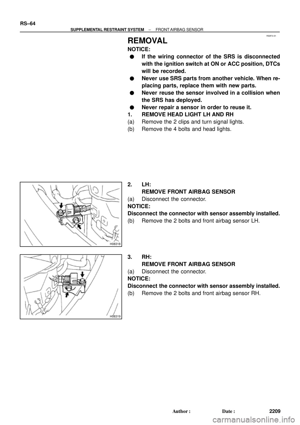
RS0F0±01
H08318
H08319
RS±64
± SUPPLEMENTAL RESTRAINT SYSTEMFRONT AIRBAG SENSOR
2209 Author�: Date�:
REMOVAL
NOTICE:
�If the wiring connector of the SRS is disconnected
with the ignition switch at ON or ACC position, DTCs
will be recorded.
�Never use SRS parts from another vehicle. When re-
placing parts, replace them with new parts.
�Never reuse the sensor involved in a collision when
the SRS has deployed.
�Never repair a sensor in order to reuse it.
1. REMOVE HEAD LIGHT LH AND RH
(a) Remove the 2 clips and turn signal lights.
(b) Remove the 4 bolts and head lights.
2. LH:
REMOVE FRONT AIRBAG SENSOR
(a) Disconnect the connector.
NOTICE:
Disconnect the connector with sensor assembly installed.
(b) Remove the 2 bolts and front airbag sensor LH.
3. RH:
REMOVE FRONT AIRBAG SENSOR
(a) Disconnect the connector.
NOTICE:
Disconnect the connector with sensor assembly installed.
(b) Remove the 2 bolts and front airbag sensor RH.
Page 3219 of 4592
 Install the front airbag sensor with")
RS01P±14
H06728
LH:
RH:
± SUPPLEMENTAL RESTRAINT SYSTEMFRONT AIRBAG SENSOR
RS±67
2212 Author�: Date�:
INSTALLATION
1. INSTALL FRONT AIRBAG SENSOR LH AND RH
(a) Install the front airbag sensor with the arrow on the sensor
facing toward the front of the vehicle.
Torque: 20 N´m (205 kgf´cm, 15 ft´lbf)
NOTICE:
�Connection of the connector is done after the sensor
assembly has been installed.
�Make sure the sensor is installed with the specified
torque.
�If the sensor has been dropped, or there are cracks,
dents or other defects in the case, brackets or con-
nector, replace the removed sensor with a new one.
�The front sensor is equipped with an electrical con-
nection check mechanism. Be sure to lock this mech-
anism securely when connecting the connector. If the
connector is not securely locked, a malfunction code
will be detected by the diagnostic system.
(b) Connect the front airbag sensor connector.
2. INSTALL HEAD LIGHT LH AND RH
(See page BE±28)
3. INSTALL TURN SIGNAL LIGHT LH AND RH
Page 3303 of 4592
7.17263 in.´lbf")
SS06M±01
± SERVICE SPECIFICATIONSSTEERING
SS±65
228 Author�: Date�:
TORQUE SPECIFICATION
Part tightenedN´mkgf´cmft´lbf
STEERING COLUMN
Steering wheel pad set screw (Torx screw)7.17263 in.´lbf
Steering wheel set nut3536026
Intermediate shaft assembly x Control valve shaft3536026
Steering column assembly x Intermediate shaft assembly3536026
Steering column assembly set nut2526019
Turn signal bracket x Column tube77061 in.´lbf
Lower column tube attachment x Column tube1919514
PS VANE PUMP
5S±FE and 1MZ±FE Engines:
Pressure feed tube x Control valve housing 5S±FE Engine32 (25)326 (250)24 (18)
Pressure feed tube x Pressure feed tube 1MZ±FE Engine20 (25)203 (250)15 (18)
Clamp plate set nut 5S±FE Engine101007
Clamp plate set nut 1MZ±FE Engine7.88069 in.´lbf
PS vane pump set bolt A bolt29 (43)293 (440)21 (32)
PS vane pump set bolt B bolt4344032
Oil pressure switch x Union bolt2121015
Union bolt x Pressure feed tube5252538
Vane pump pulley set nut4344032
Front bracket x Rear bracket4344032
Suction port union set bolt131309
Pressure port union8385062
Rear housing set bolt2424017
PS GEAR
Pressure feed tube clamp plate set nut101007
Pressure feed and return tubes x Control valve housing32 (25)326 (250)24 (18)
Stabilizer bar set bolt1919514
PS gear assembly set bolt and nut1811,850134
Turn pressure tube union nut10 (13)102 (130)7 (9)
Tie rod end lock nut7475054
Rack x Rack end60 (83)615 (850)45 (62)
Rack guide spring cap lock nut50 (69)513 (700)37 (51)
Rack housing cap5960043
Selt±locking nut2525018
Control valve housing set bolt1818513
( ): For use without SST
Page 3305 of 4592

USA:
Standard indicat")
SS0B0±05
± SERVICE SPECIFICATIONSBODY ELECTRICAL
SS±67
230 Author�: Date�:
BODY ELECTRICAL
SERVICE DATA
TURN SIGNAL FLASHER
Flashes/ Minute60 ± 120
SPEEDOMETER (ON±VEHICLE)
USA:
Standard indication (mph)Allowable range (mph)
2018 ± 24
4038 ± 44
6056 ± 66
8078 ± 88
10098 ± 110
120118 ± 132
CANADA:
Standard indication (km/h)Allowable range (km/h)
2017 ± 24
4038 ± 46
6057.5 ± 67
8077 ± 88
10096 ± 109
120115 ± 130
140134 ± 151.5
160153 ± 173
TACHOMETER (ON±VEHICLE)/ DC 13.5 V 25 °C at (77 °F)
Standard indicationAllowable range
700630 ± 770
1,000900 ± 1,100
2,0001,850 ± 2,150
3,0002,800 ± 3,200
4,0003,800 ± 4,200
5,0004,800 ± 5,200
6,0005,750 ± 6,250
7,0006,700 ± 7,300
FUEL RECEIVER GAUGE
A ± BApprox. 126.2 W
A ± CApprox. 280.5 W
B ± CApprox. 154.3 W
FUEL SENDER GAUGE
Float position mm (in.)Resistance (W)
F: Approx. ±91.1 (±3.587)Approx. 3.0
1/2: Approx. ±34.2 (±1.346)Approx. 31.7
E: Approx. 30.8 (1.213)Approx. 110.0
ENGINE COOLANT TEMPERATURE RECEIVER GAUGE (Resistance)
A ± BApprox. 175.7 W
A ± CApprox. 54.0 W

 : Specified torqueFront Airbag Sensor (RH)Front Airbag Sensor (LH)
20 (205, 15)
20 (205, 15)
20 (205, 15)
Turn Signal Light RH
Turn Signal Light LH
Head Light")