Page 1423 of 2267

CHECK SUPER LOCK ACTUATOR CIR-
CUIT.
Check voltage for super lock actuator.
Note:
Put the system in set conditio")
DIAGNOSTIC PROCEDURE 4
—Type-2 for Super Lock Actuator—
(Super lock actuator check)
CHECK SUPER LOCK ACTUATOR CIR-
CUIT.
Check voltage for super lock actuator.
Note:
Put the system in set condition before
checking release signal.
OK
�NG
Super lock actuator
is OK.
CHECK SUPER LOCK ACTUATOR.
1. Disconnect door lock actuator assembly
connector.
2. Set lever A in lock position.
3. Apply 12V direct current to door lock
actuator assembly and check operation.
Driver side
Passenger side
Rear door
NG
�OK
Check harness
between control unit
and door lock actua-
tor assembly.
Replace door lock actuator assembly.
Door key cylin-
der switch con-
ditionTerminals
Voltage
(V)
��
Lock (Set)
�40Ground
Approx. 12
Unlock
(Released)
�44Ground
Super
lock
actuator
operationTerminalsConnec-
tion from
lever A
to lever B
��
Released
,Set
�1: (LHD)
�6: (RHD)�4: (LHD)
�3: (RHD)Discon-
nect
Set,
Released
�4: (LHD)
�3: (RHD)�1: (LHD)
�6: (RHD)Connect
Super
lock
actuator
operationTerminalsConnec-
tion from
lever A
to lever B
��
Released
,Set
�4: (LHD)
�3: (RHD)�1: (LHD)
�6: (RHD)Discon-
nect
Set,
Released
�1: (LHD)
�6: (RHD)�4: (LHD)
�3: (RHD)Connect
Super
lock
actuator
operationTerminalsConnec-
tion from
lever A
to lever B
��
Released
,Set
�1: (LH)
�6: (RH)
�4: (LH)
�3: (RH)Discon-
nect
Set,
Released
�4: (LH)
�3: (RH)
�1: (LH)
�6: (RH)Connect
YEL449B
Time control unit connector
YEL822
Door lock actuator
assembly connector
Driver side:
LHD model
RHD model
Lever B
Front
Lock
Lever
A
Door lock
actuator
assemblyDoor lock
actuator
assembly Lock
Lever
A FrontLever B
YEL023A
Door lock actuator
assembly connector
Passenger side: LHD modelRHD model
YEL255A
Door lock actuator assembly connector
Rear door LHRear door RH
�
�
POWER DOOR LOCK—Super Lock—
Trouble Diagnoses (Cont’d)
EL-291
Page 1424 of 2267

CHECK DOOR SWITCH INPUT SIG-
NAL.
Check voltage between fuse block (J/B)
and ground.
NG
�OK
Door switch is OK.
CHECK GRO")
DIAGNOSTIC PROCEDURE 5
—With driver door switch type-1—
(Door switch check)
CHECK DOOR SWITCH INPUT SIG-
NAL.
Check voltage between fuse block (J/B)
and ground.
NG
�OK
Door switch is OK.
CHECK GROUND CIRCUIT.
1) Disconnect driver side door switch
connector.
2) Check harness continuity between
terminal
�2and ground.
Continuity should exist.
OK
�NG
Repair harness or con-
nector.
CHECK DOOR SWITCH.
1) Disconnect door switch connector.
2) Check continuity between door
switch terminals.
OK
�NG
Replace door switch.
Check the following.
�Door switch ground condition (Except
driver side)
�Harness for open or short between
control unit and door switch
Termi-
nalsCondition Voltage [V]
Driver
side door
16JOpened 0
Closed Approx. 12
Other
door
7JOpened 0
Closed Approx. 12
Terminals ConditionContinu-
ity
Driver
side door
switch
�2-�3Closed No
Open Yes
Other
door
switches
�1-
groundClosed No
Open Yes
YEL450B
Fuse block (J/B) connector
YEL831
Door switch connector
Driver side:
YEL830
Door switch connector
Driver side:
Door switch connector
Passenger side:
Rear side:
�
�
�
POWER DOOR LOCK—Super Lock—
Trouble Diagnoses (Cont’d)
EL-292
Page 1425 of 2267
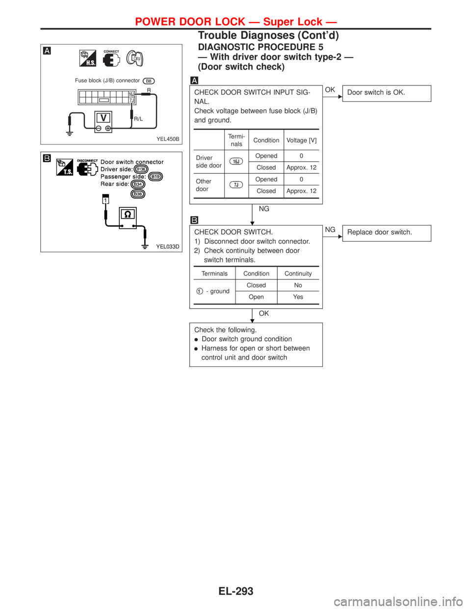
DIAGNOSTIC PROCEDURE 5
—With driver door switch type-2—
(Door switch check)
CHECK DOOR SWITCH INPUT SIG-
NAL.
Check voltage between fuse block (J/B)
and ground.
NG
�OK
Door switch is OK.
CHECK DOOR SWITCH.
1) Disconnect door switch connector.
2) Check continuity between door
switch terminals.
OK
�NG
Replace door switch.
Check the following.
�Door switch ground condition
�Harness for open or short between
control unit and door switch
Termi-
nalsCondition Voltage [V]
Driver
side door
16JOpened 0
Closed Approx. 12
Other
door
7JOpened 0
Closed Approx. 12
Terminals Condition Continuity
�1- groundClosed No
Open Yes
YEL450B
Fuse block (J/B) connector
YEL033D
�
�
POWER DOOR LOCK—Super Lock—
Trouble Diagnoses (Cont’d)
EL-293
Page 1426 of 2267
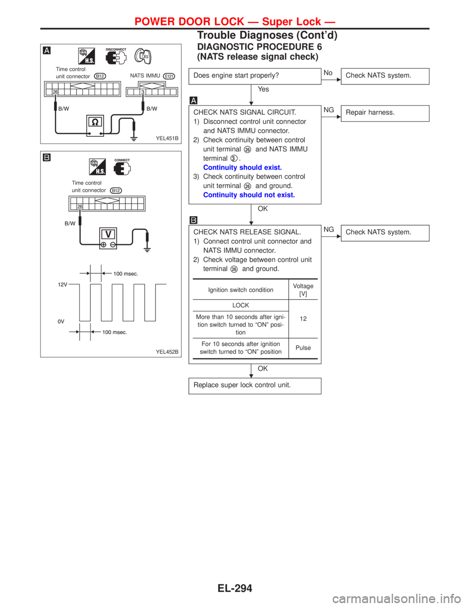
DIAGNOSTIC PROCEDURE 6
(NATS release signal check)
Does engine start properly?
Ye s
�No
Check NATS system.
CHECK NATS SIGNAL CIRCUIT.
1) Disconnect control unit connector
and NATS IMMU connector.
2) Check continuity between control
unit terminal
�26and NATS IMMU
terminal
�3.
Continuity should exist.
3) Check continuity between control
unit terminal
�26and ground.
Continuity should not exist.
OK
�NG
Repair harness.
CHECK NATS RELEASE SIGNAL.
1) Connect control unit connector and
NATS IMMU connector.
2) Check voltage between control unit
terminal
�26and ground.
OK
�NG
Check NATS system.
Replace super lock control unit.
Ignition switch conditionVoltage
[V]
LOCK
12 More than 10 seconds after igni-
tion switch turned to“ON”posi-
tion
For 10 seconds after ignition
switch turned to“ON”positionPulse
YEL451B
Time control
unit connectorNATS IMMU
YEL452B
Time control
unit connector
�
�
�
POWER DOOR LOCK—Super Lock—
Trouble Diagnoses (Cont’d)
EL-294
Page 1427 of 2267

CHECK IGNITION KEY SWITCH
INPUT SIGNAL.
Check voltage between control unit ter-
minal
�22and ground.
NG
�OK
Key switch is OK.
CHECK KEY SWITCH POWER SUP-
PLY.")
DIAGNOSTIC PROCEDURE 7
(Key switch check)
CHECK IGNITION KEY SWITCH
INPUT SIGNAL.
Check voltage between control unit ter-
minal
�22and ground.
NG
�OK
Key switch is OK.
CHECK KEY SWITCH POWER SUP-
PLY.
Check voltage between key switch har-
ness terminal
�2and ground.
Battery voltage should exist.
OK
�NG
Check the following.
�10A fuse [No.16,
located in fuse block
(J/B)]
�Harness for open or
short between key
switch and fuse
CHECK KEY SWITCH.
1) Disconnect key switch connector.
2) Check continuity between key
switch terminals.
OK
�NG
Replace key switch.
Check harness for open or short
between control unit and key switch.
Condition of key switch Voltage [V]
Key is inserted Approx. 12
Key withdrawn 0
Terminals Condition Continuity
�1-�2
Key is
inserted.Ye s
Key is with-
drawn.No
DIAGNOSTIC PROCEDURE 8
(Ignition switch“ON”circuit check)
Terminals Ignition switch position
��OFF ACC ON
�1Ground 0V 0V Battery voltage
If NG, check the following.
�10A fuse [No.26, located in the fuse block (J/B)]
�Harness for open or short
YEL453B
Time control unit
connector
YEL826
Key switch connector
YEL827
Key switch connector
YEL454B Time control
unit connector
�
�
�
POWER DOOR LOCK—Super Lock—
Trouble Diagnoses (Cont’d)
EL-295
Page 1428 of 2267
System Description
The multi-remote control system controls operation of the
�power door lock (and super lock)
OPERATED PROCEDURE
Power door lock operation
When the following input signals are both supplied:
�Key switch OFF (when ignition key is not inserted in key cylinder);
�door switch CLOSED (when all the doors are closed);
The two above signals are already input into time control unit. At this point, time control unit receives a LOCK
signal from remote controller. Time control unit locks all doors and set super lock with input of LOCK signal
from remote controller.
When an UNLOCK signal is sent from remote controller once, driver’s door will be unlocked and release
super lock.
Then, if an UNLOCK signal is sent from remote controller again, all other door will be unlocked.
Multi-remote controller ID code entry
For detailed procedure, refer to“ID Code Entry Procedure”in EL-305.
MULTI-REMOTE CONTROL SYSTEM
EL-296
Page 1429 of 2267
Schematic
YEL206C
IGNITION SWITCH
On or STARTBATTERYBATTERY
(Via fusible link)
FUSEFUSE
FUSIBLE
LINK
TIME CONTROL UNITTo door lock
actuators
DOOR LOCK
ACTUATOR
ASSEMBLY
(DRIVER’S SIDE)DOOR LOCK
ACTUATOR
ASSEMBLY
(REAR LH)
UNLOCK
SENSOR
UNLOCK
SENSOR DOOR LOCK
ACTUATOR
ASSEMBLY
(REAR RH) DOOR LOCK
ACTUATOR
ASSEMBLY
(PASSENGER SIDE)UNLOCK
SENSOR
UNLOCK
SENSOR
TRUNK OR
LUGGAGE
ROOM
LAMP SWITCH FRONT
DOOR
SWITCH
(DRIVER’S
SIDE)FRONT
DOOR
SWITCH
(PASSENGER
SIDE)REAR
DOOR
SWITCH
LHREAR
DOOR
SWITCH
RH
UNLOCK
UNLOCKUNLOCK
UNLOCK
KEY
SWITCHCIRCUIT
BREAKER-1
LOCK
LOCK LOCK
LOCK
MULTI-REMOTE CONTROL SYSTEM
EL-297
Page 1435 of 2267
 Unlock the vehicle by a mechanical key in the drivers door key cylinder.
N")
Trouble Diagnoses
If no doors can not be unlocked by remote controller operation then the following procedure is required.
A) Unlock the vehicle by a mechanical key in the drivers door key cylinder.
Note: this may cause the alarm to sound.
B) Put the key in ignition, turn to ON position for at least five seconds. Assuming the ignition key contains
a valid transponder then a signal will be generated by the immobilizer which will disarm the alarm and
allow key learn mode to be entered.
C) Turn ignition OFF and wait for ten seconds.
SYMPTOM CHART
Symptom Possible cause Diagnoses/service order
No doors can be locked or
unlocked by remote control
operation.1. Remote controller battery
2. Power door lock system
3. Key switch (insert)
4. Door switch
5. Power supply circuit for time
control unit
6. Ground circuit for time control
unit
7. Remote controller1. Check remote controller battery. Refer to EL-304.
2. Check that power door lock operates properly. If
NG, check power door lock.
3. Check key switch (insert) signal at terminal
�22
of time control unit.
4. Check door switch signal at terminals
�6and
�7of time control unit.
5. Make sure battery voltage is present at terminal
�9of time control unit.
6. Check continuity between terminal
�16of time
control unit and ground.
7. Replace remote controller. Refer to EL-305.
The new ID of remote controller
cannot be entered.1. Remote controller battery
2. Key switch (insert)
3. Door switch
4. Driver’s door unlock sensor
5. Ignition ON power supply
circuit for time control unit
6. Remote controller1. Check remote controller battery. Refer to EL-304.
2. Check key switch (insert) signal at terminal
�29
of time control unit.
3. Check door switch signal at terminals
�6and
�7of time control unit.
4. Check driver’s door unlock sensor signal at termi-
nal
�35of time control unit.
5. Make sure battery voltage is present at terminal
�1of time control unit while ignition switch is in
ON position.
6. Replace remote controller. Refer to EL-305.
Refer to“TIME CONTROL UNIT INSPECTION TABLE”on next page to check the control unit signals.
NOTE:
�The unlock operation of multi-remote control system does not activate with key inserted in the ignition
key cylinder.
�The lock operation of multi-remote controller does not activate with the key inserted ignition key cylin-
der or if one of the door is opened.
MULTI-REMOTE CONTROL SYSTEM
EL-303

FUSEFUSE
FUSIBLE
LINK
TIME CONTROL UNITTo door lock
actuators
DOOR LOCK
ACTUATOR
ASSEMBLY
(DRIVER’S SIDE)DOOR LOCK
ACTU")