1999 NISSAN PRIMERA door lock
[x] Cancel search: door lockPage 1971 of 2267
Evaporative emission (EVAP)
system ...............................EC-QG-25, EC-SR-27
Exhaust gas recirculation (EGR)
valve...........................................EC-QG-244, 305
Exhaust system ................................................FE-9
Exhaust system inspection ............................MA-48
Exterior ............................................................BT-31
F
FCUT - Wiring diagram ..........................EC-CD-101
F/FOG - Wiring diagram................................EL-110
Final drive (FF M/T) ...........................MT-32, 51, 71
Floor trim .........................................................BT-18
Fluid temperature sensor (A/T) .......................AT-94
Fluids..............................................................MA-16
Flywheel (clutch) .............................................CL-14
Flywheel runout..............................EM-60, 117, 177
Fog lamp, front ..............................................EL-110
Fog lamp, rear ...............................................EL-112
F/PUMP - Wiring
diagram..........................EC-QG-338, EC-SR-317
Freeze frame data ................EC-QG-38, EC-SR-50
Fresh vent door control linkage
adjustment ..................................................HA-83
FRO2 - Wiring diagram ........EC-QG-135, 154, 162,
EC-SR-147, 165, 172
FRO2/H - Wiring
diagram..........................EC-QG-168, EC-SR-177
Front axle ..........................................................FA-9
Front bumper ....................................................BT-5
Front disc brake .............................................BR-23
Front door .......................................................BT-13
Front fog lamp .......................................EL-110, 111
Front fog lamp removal and installation ...........BT-5
Front heated oxygen sensor
(HO2S) ......................................EC-QG-132, 139,
EC-SR-144, 150, 156, 162, 170
Front heated oxygen sensor (HO2S)
heater ............................EC-QG-166, EC-SR-175
Front passenger air bag .................................RS-17
Front seat ........................................................BT-40
Front seat belt ..................................................RS-3
Front suspension ............................................FA-26
Front washer .................................................EL-186
Front wiper ....................................................EL-186
FTS - Wiring diagram ............................EC-CD-105
FUEL - Wiring
diagram .........EC-QG-210, 217, EC-SR-213, 220
Fuel cut control (at no load & high
engine speed)....................EC-QG-25, EC-SR-27
Fuel cut solenoid valve ..........................EC-CD-100
Fuel filter ...............................EC-QG-29, EC-SR-31
Fuel filter replacement .......................MA-23, 33, 43
Fuel gauge ............................................EL-141, 146
Fuel injection system....................EC-QG-208, 215,
EC-SR-212, 218,
EC-CD-15, 18
Fuel injector ......................EC-QG-318, EC-SR-302
Fuel line inspection............................MA-22, 33, 43Fuel precautions ................................................GI-7
Fuel pressure check .............EC-QG-29, EC-SR-31
Fuel pressure regulator .........EC-QG-30, EC-SR-32
Fuel pressure release ...........EC-QG-29, EC-SR-31
Fuel pump .........................EC-QG-336, EC-SR-316
Fuel pump and gauge ......................................FE-7
Fuel pump relay ................EC-QG-336, EC-SR-316
Fuel system ......................................................FE-6
Fuel tank vacuum relief
valve ..................................EC-QG-26, EC-SR-28
Fuel temperature sensor .................EC-CD-17, 104
Fuse ..................................................EL-22, Foldout
Fuse block ....................................................Foldout
Fusible link ........................................EL-22, Foldout
G
Garage jack and safety stand .........................GI-47
Gauges..........................................................EL-138
Gear components (M/T) ...........................MT-16, 49
Generic scan tool (GST) .......EC-QG-66, EC-SR-78
GLOW - Wiring diagram ........................EC-CD-120
Glow plug .........................................EC-CD-15, 118
Glow relay ................................................EC-CD-15
GOVNR - Wiring diagram ........................EC-CD-79
Grille - See Exterior ........................................BT-38
Ground distribution..........................................EL-23
H
H/AIM - Wiring diagram ....................EL-87, 93, 200
Harness connector ............................................EL-6
Harness layout ..............................................EL-368
Hazard warning lamp ....................................EL-117
Headlamp..................................................EL-67, 69
Headlamp aiming control ................................EL-87
Headlamp washer .........................................EL-200
Headlining - See Roof trim .............................BT-25
Heated oxygen sensor (HO2S)
(front) ........................................EC-QG-132, 139,
EC-SR-144, 150, 156, 162, 170
Heated oxygen sensor (HO2S) heater
(front) .............................EC-QG-166, EC-SR-175
Heated oxygen sensor (HO2S) heater
(rear) ..............................EC-QG-203, EC-SR-207
Heated oxygen sensor (rear) ...............EC-QG-171,
EC-SR-180, 187,
194, 201
Heated oxygen sensor inspection ...........MA-27, 38
Heated seat .......................................BT-42, EL-234
HEATER - Wiring diagram .............................HA-40
HFC134a (R134a) system service
procedure ..................................................HA-100
HFC134a (R134a) system service tools ..........HA-8
H/LAMP - Wiring diagram ...............................EL-67
Hood..................................................................BT-5
Horn ..............................................................EL-203
HORN - Wiring diagram ................................EL-203
ALPHABETICAL INDEX
IDX-4
Page 1972 of 2267
How to erase DTC for OBD
system ...............................EC-QG-44, EC-SR-56
HSEAT - Wiring diagram...............................EL-234
Hydraulic lash adjuster inspection .........EM-96, 189
I
IACV-AAC valve ................EC-QG-274, EC-SR-263
IATS - Wiring diagram .......EC-QG-117, EC-SR-128
Identification plate............................................GI-44
Idle air control (IAC)
system ...........................EC-QG-274, EC-SR-263
Idle air control valve
(IACV) ............................EC-QG-274, EC-SR-263
Idle mixture ratio ...................EC-QG-32, EC-SR-34
Idle speed .............................EC-QG-32, EC-SR-34
IGN/SG - Wiring diagram .......................EC-SR-308
Ignition coil .............................................EC-SR-310
Ignition control system ......EC-QG-323, EC-SR-306
Ignition timing ........................EC-QG-32, EC-SR-34
Ignition wire inspection ..............MA-36, EC-SR-229
ILL - Wiring diagram .....................................EL-125
Illumination ....................................................EL-124
INJECT - Wiring diagram ..EC-QG-319, EC-SR-303
Injection nozzle inspection .............................MA-46
Injection timing control valve ...................EC-CD-82
Injector ...................................................EC-QG-318
Injector removal and
installation..........................EC-QG-30, EC-SR-32
Input shaft (FF M/T) .................................MT-21, 58
Instrument panel .............................................BT-15
INT/L - Wiring diagram..................................EL-132
Intake air temparature
sensor ............................EC-QG-116, EC-SR-127
Intake door control linkage adjustment ..........HA-83
Intake door motor .....................................HA-81, 83
Intake valve timing control solenoid
valve ...................................................EC-QG-284
Interior .............................................................BT-18
Interior lamp ..........................................EL-124, 130
K
Knock sensor (KS) .......................EC-QG-228, 229,
EC-SR-230, 231
KS - Wiring diagram ..............................EC-QG-229
L
License lamp .................................................EL-100
Lifting points ....................................................GI-46
Line pressure solenoid valve ..........................AT-74
Line pressure test (A/T) ..................................AT-35
Liquid gasket application .................................EM-5
LOAD - Wiring diagram .........................EC-QG-352
Location of electrical units ............................EL-365
Lubricants.......................................................MA-16Lubrication circuit (engine) ...................LC-4, 15, 26
Lubrication-locks, hinges and hood
latches ........................................................MA-54
Luggage compartment trim .............................BT-29
Luggage room lamp ......................................EL-131
M
MAFS - Wiring
diagram .......EC-QG-112, EC-SR-122, EC-CD-63
MAIN - Wiring
diagram .......EC-QG-103, EC-SR-115, EC-CD-59
Mainshaft (M/T) ........................................MT-24, 63
Malfunction indicator lamp
(MIL) ..................................EC-QG-45, EC-SR-58
Manual transmission number ..........................GI-44
Manual transmission oil replacement ......MA-48, 49
Mass air flow sensor
(MAFS)........EC-QG-110, EC-SR-120, EC-CD-62
METER - Wiring diagram .....................EL-141, 146
MIL & Data link connectors
circuit .............................EC-QG-354, EC-SR-329
MIL/DL - Wiring
diagram .....EC-QG-354, EC-SR-329, EC-CD-142
MIRROR - Wiring diagram ............................EL-231
Mirror defogger .............................................EL-207
Mirror, door......................................................BT-58
Mirror, out side ................................................BT-58
Misfire ................................EC-QG-222, EC-SR-224
Mode door control linkage adjustment ...........HA-82
Model variation ................................................GI-41
Molding - See Exterior ....................................BT-31
M/T major overhaul ..................................MT-14, 47
M/T removal and installation ..........................MT-10
Mud guard - See Exterior ...............................BT-37
MULTI - Wiring diagram ................................EL-298
Multi-remote control system..........................EL-296
Multiport fuel injection (MFI)
system ...............................EC-QG-21, EC-SR-23
Multiport fuel injection precautions ....................GI-6
N
NATS (Nissan anti-theft system)...................EL-342
NATS (Nissan anti-theft system)
precautions ..............................................GI-3, 25
NATS - Wiring diagram .................................EL-343
Needle lift sensor .....................................EC-CD-97
Neutral position switch ......EC-QG-313, EC-SR-298
NLS - Wiring diagram ..............................EC-CD-98
NVH troubleshooting (BR)................................BR-6
NVH troubleshooting (CL) ................................CL-3
NVH troubleshooting (EM) ...............EM-11, 64, 121
NVH troubleshooting (M/T) ..............................MT-7
NVH troubleshooting (RA)................................RA-3
ALPHABETICAL INDEX
IDX-5
Page 1973 of 2267
O
Oil cooler (engine) ....................................LC-20, 30
Oil pan (engine) ...............................EM-17, 70, 129
Oil pressure (engine)............................LC-5, 16, 27
Oil pump (engine).................................LC-5, 17, 27
Oil pump regulator valve (engine) ....................LC-7
Oil seal replacement
(engine) ................................EM-29, 84, 138, 139
On board diagnostic
system ...............................EC-QG-36, EC-SR-48
Operational check (cool box) .........................HA-24
P
Park/Neutral position
switch.............................EC-QG-313, EC-SR-298
Park/neutral position switch (A/T) ...................AT-48
Parking brake control .....................................BR-48
Parking lamp .................................................EL-100
PCV (positive crankcase
ventilation) .........................EC-QG-28, EC-SR-30
PCV system inspection............................MA-26, 36
Periodic maintenance (for Europe) ..................MA-6
PGC/V - Wiring diagram ...EC-QG-264, EC-SR-252
PHASE - Wiring diagram .......................EC-QG-240
Pilot bushing replacement - See Pilot
converter ...................................................EM-117
Piston assembly..............EM-53, 60, 110, 117, 167,
175, 176, 185, 193, 199
Piston pin inspection.............EM-54, 110, 168, 171,
185, 193, 199
Piston ring inspection ....................EM-54, 111, 168,
185, 193, 199
Piston to bore clearance........................EM-56, 174
PNP/SW - Wiring
diagram..........................EC-QG-315, EC-SR-300
POWER - Wiring diagram...............................EL-12
Power door lock ....................................EL-245, 265
Power door mirror .........................................EL-231
Power seat ....................................................EL-233
Power steering fluid level...............................MA-53
Power steering oil pressure
switch.............................EC-QG-342, EC-SR-321
Power supply routing ......................................EL-10
Power transistor......................................EC-SR-311
Power transistor & ignition coil ..............EC-SR-306
Power window ...............................................EL-236
Pre-delivery inspection.....................................MA-4
Precautions (General) .......................................GI-4
Pressure test (A/T) ..........................................AT-35
PST/SW - Wiring
diagram..........................EC-QG-343, EC-SR-322
R
Radiator ..........................................LC-9, 13, 25, 36Rear axle (disc brake type) ..............................RA-5
Rear bumper ...........................................BT-7, 9, 11
Rear combination lamp removal and
installation ...................................................BT-37
Rear disc brake ........................................BR-33, 40
Rear door ........................................................BT-14
Rear drum brake ............................................BR-44
Rear fog lamp................................................EL-112
Rear heated oxygen sensor
(HO2S) ..EC-QG-171, EC-SR-180, 187, 194, 201
Rear heated oxygen sensor (HO2S)
heater ............................EC-QG-203, EC-SR-207
Rear seat ........................................................BT-43
Rear seat belt ...................................................RS-4
Rear suspension ..............................................RA-4
Rear washer..................................................EL-193
Rear window ...................................................BT-53
Rear window defogger ..................................EL-207
Rear wiper.....................................................EL-193
Refrigerant connection precaution ...................HA-4
Refrigerant general precaution.........................HA-4
Refrigerant lines ...........................................HA-104
Refrigerant pressure
sensor....................EC-QG-299, 347, EC-SR-289
Refrigeration cycle..........................................HA-12
Removal and installation (A/T) ......................AT-116
Revolution sensor (A/T) ............................AT-61, 65
R/FOG - Wiring diagram ...............................EL-112
Roof trim .........................................................BT-25
RRO2 - Wiring
diagram.....................EC-QG-174, 183, 191, 199,
EC-SR-183, 190, 197, 203
RRO2/H - Wiring
diagram..........................EC-QG-205, EC-SR-209
S
SAE J1930 terminology list .............................GI-51
Seal - See Exterior .........................................BT-31
SEAT - Wiring diagram .................................EL-233
Seat belt inspection .......................................MA-54
Seat belt pre-tensioner ...................................RS-13
Seat belt pre-tensioner disposal ....................RS-27
Seat, front .......................................................BT-40
Self-diagnostic results ...........EC-QG-46, EC-SR-59
Shift control components (M/T) .........MT-17, 50, 74
Shock absorber (rear).....................................RA-11
Side air bag ....................................................RS-19
Side trim ..........................................................BT-18
Side window - See Rear side window ............BT-55
S/LOCK - Wiring diagram .....................EL-248, 270
Spark plug replacement...........................MA-25, 35
Speedometer ........................................EL-141, 146
Spiral cable.....................................................RS-14
Spot lamp..............................................EL-130, 131
SROOF - Wiring diagram .............................EL-230
SRS - See Supplemental Restraint
System ..........................................................RS-8
SRS - Wiring diagram ....................................RS-33
ALPHABETICAL INDEX
IDX-6
Page 2021 of 2267
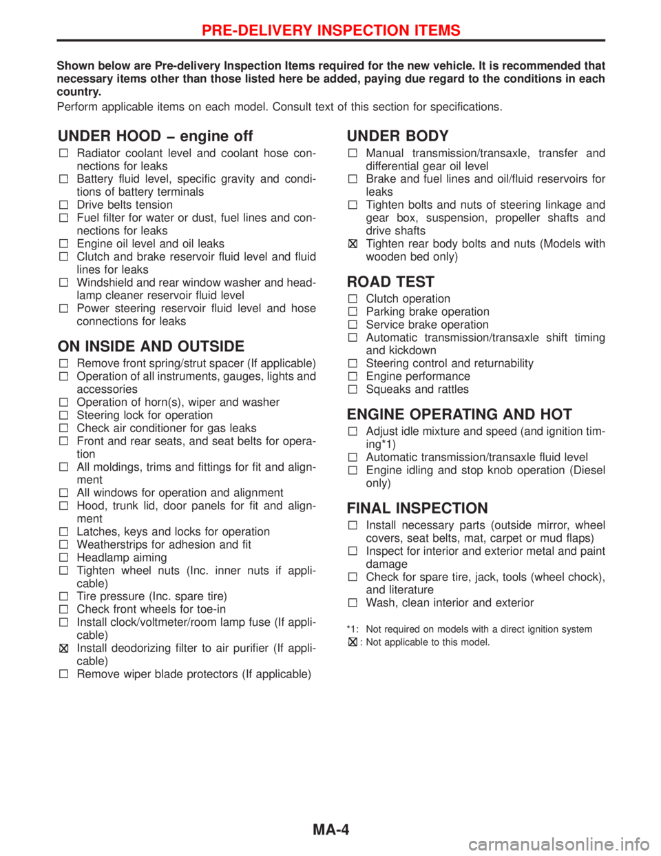
Shown below are Pre-delivery Inspection Items required for the new vehicle. It is recommended that
necessary items other than those listed here be added, paying due regard to the conditions in each
country.
Perform applicable items on each model. Consult text of this section for specifications.
UNDER HOOD � engine off
Radiator coolant level and coolant hose con-
nections for leaks
Battery fluid level, specific gravity and condi-
tions of battery terminals
Drive belts tension
Fuel filter for water or dust, fuel lines and con-
nections for leaks
Engine oil level and oil leaks
Clutch and brake reservoir fluid level and fluid
lines for leaks
Windshield and rear window washer and head-
lamp cleaner reservoir fluid level
Power steering reservoir fluid level and hose
connections for leaks
ON INSIDE AND OUTSIDE
Remove front spring/strut spacer (If applicable)
Operation of all instruments, gauges, lights and
accessories
Operation of horn(s), wiper and washer
Steering lock for operation
Check air conditioner for gas leaks
Front and rear seats, and seat belts for opera-
tion
All moldings, trims and fittings for fit and align-
ment
All windows for operation and alignment
Hood, trunk lid, door panels for fit and align-
ment
Latches, keys and locks for operation
Weatherstrips for adhesion and fit
Headlamp aiming
Tighten wheel nuts (Inc. inner nuts if appli-
cable)
Tire pressure (Inc. spare tire)
Check front wheels for toe-in
Install clock/voltmeter/room lamp fuse (If appli-
cable)
Install deodorizing filter to air purifier (If appli-
cable)
Remove wiper blade protectors (If applicable)
UNDER BODY
Manual transmission/transaxle, transfer and
differential gear oil level
Brake and fuel lines and oil/fluid reservoirs for
leaks
Tighten bolts and nuts of steering linkage and
gear box, suspension, propeller shafts and
drive shafts
Tighten rear body bolts and nuts (Models with
wooden bed only)
ROAD TEST
Clutch operation
Parking brake operation
Service brake operation
Automatic transmission/transaxle shift timing
and kickdown
Steering control and returnability
Engine performance
Squeaks and rattles
ENGINE OPERATING AND HOT
Adjust idle mixture and speed (and ignition tim-
ing*1)
Automatic transmission/transaxle fluid level
Engine idling and stop knob operation (Diesel
only)
FINAL INSPECTION
Install necessary parts (outside mirror, wheel
covers, seat belts, mat, carpet or mud flaps)
Inspect for interior and exterior metal and paint
damage
Check for spare tire, jack, tools (wheel chock),
and literature
Wash, clean interior and exterior
*1: Not required on models with a direct ignition system
: Not applicable to this model.
PRE-DELIVERY INSPECTION ITEMS
MA-4
Page 2022 of 2267
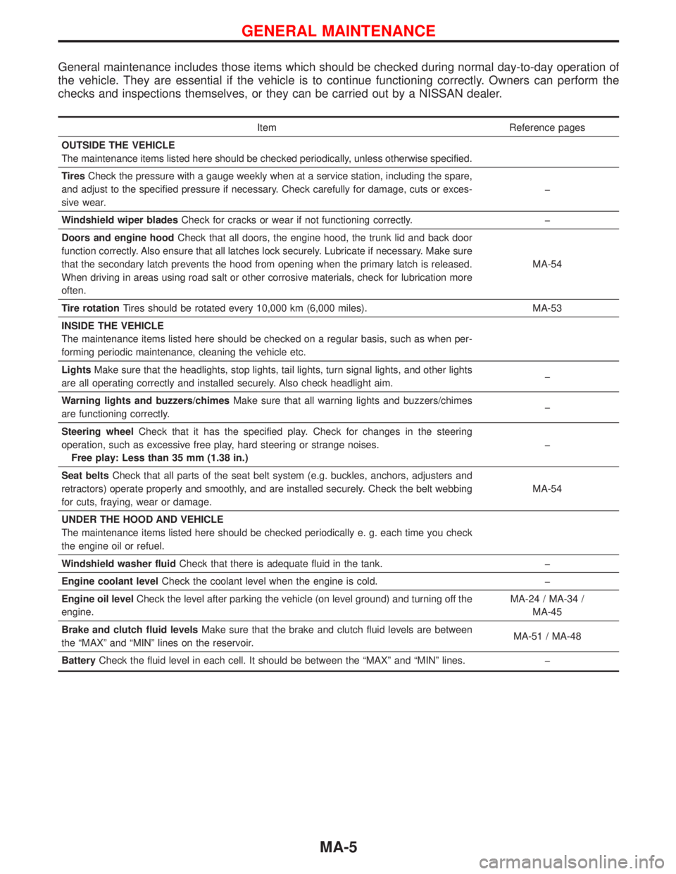
General maintenance includes those items which should be checked during normal day-to-day operation of
the vehicle. They are essential if the vehicle is to continue functioning correctly. Owners can perform the
checks and inspections themselves, or they can be carried out by a NISSAN dealer.
Item Reference pages
OUTSIDE THE VEHICLE
The maintenance items listed here should be checked periodically, unless otherwise specified.
TiresCheck the pressure with a gauge weekly when at a service station, including the spare,
and adjust to the specified pressure if necessary. Check carefully for damage, cuts or exces-
sive wear.�
Windshield wiper bladesCheck for cracks or wear if not functioning correctly.�
Doors and engine hoodCheck that all doors, the engine hood, the trunk lid and back door
function correctly. Also ensure that all latches lock securely. Lubricate if necessary. Make sure
that the secondary latch prevents the hood from opening when the primary latch is released.
When driving in areas using road salt or other corrosive materials, check for lubrication more
often.MA-54
Tire rotationTires should be rotated every 10,000 km (6,000 miles). MA-53
INSIDE THE VEHICLE
The maintenance items listed here should be checked on a regular basis, such as when per-
forming periodic maintenance, cleaning the vehicle etc.
LightsMake sure that the headlights, stop lights, tail lights, turn signal lights, and other lights
are all operating correctly and installed securely. Also check headlight aim.�
Warning lights and buzzers/chimesMake sure that all warning lights and buzzers/chimes
are functioning correctly.�
Steering wheelCheck that it has the specified play. Check for changes in the steering
operation, such as excessive free play, hard steering or strange noises.
Free play: Less than 35 mm (1.38 in.)�
Seat beltsCheck that all parts of the seat belt system (e.g. buckles, anchors, adjusters and
retractors) operate properly and smoothly, and are installed securely. Check the belt webbing
for cuts, fraying, wear or damage.MA-54
UNDER THE HOOD AND VEHICLE
The maintenance items listed here should be checked periodically e. g. each time you check
the engine oil or refuel.
Windshield washer fluidCheck that there is adequate fluid in the tank.�
Engine coolant levelCheck the coolant level when the engine is cold.�
Engine oil levelCheck the level after parking the vehicle (on level ground) and turning off the
engine.MA-24 / MA-34 /
MA-45
Brake and clutch fluid levelsMake sure that the brake and clutch fluid levels are between
the“MAX”and“MIN”lines on the reservoir.MA-51 / MA-48
BatteryCheck the fluid level in each cell. It should be between the“MAX”and“MIN”lines.�
GENERAL MAINTENANCE
MA-5
Page 2189 of 2267
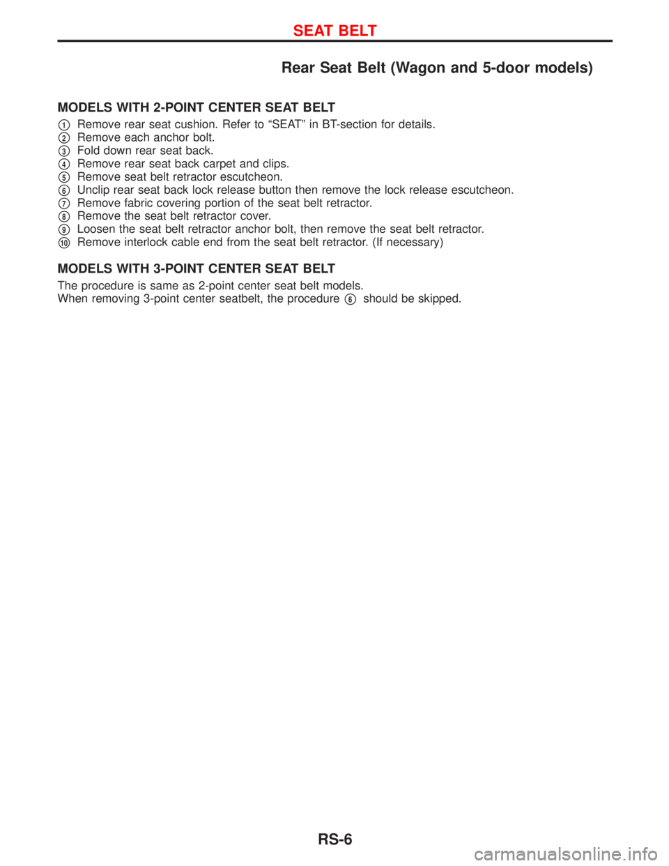
Rear Seat Belt (Wagon and 5-door models)
MODELS WITH 2-POINT CENTER SEAT BELT
p1Remove rear seat cushion. Refer to ªSEATº in BT-section for details.
p2Remove each anchor bolt.
p3Fold down rear seat back.
p4Remove rear seat back carpet and clips.
p5Remove seat belt retractor escutcheon.
p6Unclip rear seat back lock release button then remove the lock release escutcheon.
p7Remove fabric covering portion of the seat belt retractor.
p8Remove the seat belt retractor cover.
p9Loosen the seat belt retractor anchor bolt, then remove the seat belt retractor.
p10Remove interlock cable end from the seat belt retractor. (If necessary)
MODELS WITH 3-POINT CENTER SEAT BELT
The procedure is same as 2-point center seat belt models.
When removing 3-point center seatbelt, the procedure
p6should be skipped.
SEAT BELT
RS-6
Page 2205 of 2267
Disposal of Air Bag Module and Seat Belt
Pre-tensioner
lBefore disposing of air bag module and seat belt pre-tensioner, or vehicles equipped with such systems,
deploy the systems. If such systems have already been deployed due to an accident, dispose of as
indicated in ªDISPOSING OF AIR BAG MODULE AND SEAT BELT PRE-TENSIONERº (RS-27).
lWhen deploying the air bag module and seat belt pre-tensioner, always use the Special Service Tool;
Deployment tool KV99106400.
lWhen deploying the air bag module and seat belt pre-tensioner, stand at least 5 m (16 ft) away from
deployment component.
lWhen deploying air bag module and seat belt pre-tensioner a fairly loud noise is made, followed by
smoke being released. The smoke is not poisonous, however, be careful not to inhale smoke since it
irritates the throat and can cause choking.
lAlways activate one air bag module at a time.
lDue to heat, leave air bag module unattended for more than 30 minutes after deployment. Also leave
seat belt pre-tensioner unattended for more than 10 minutes after deployment.
lBe sure to wear gloves when handling a deployed air bag module and seat belt pre-tensioner.
lNever apply water to a deployed air bag module and seat belt pre-tensioner.
lWash your hands clean after finishing work.
lPlace the vehicle outdoors with an open space of at least 6 m (20 ft) on all sides when deploying air
bag module and seat belt pre-tensioner while mounted in vehicle.
lUse a voltmeter to make sure the vehicle battery is fully charged.
lDo not dispose of the air bag module and seat belt pre-tensioner un-deployed.
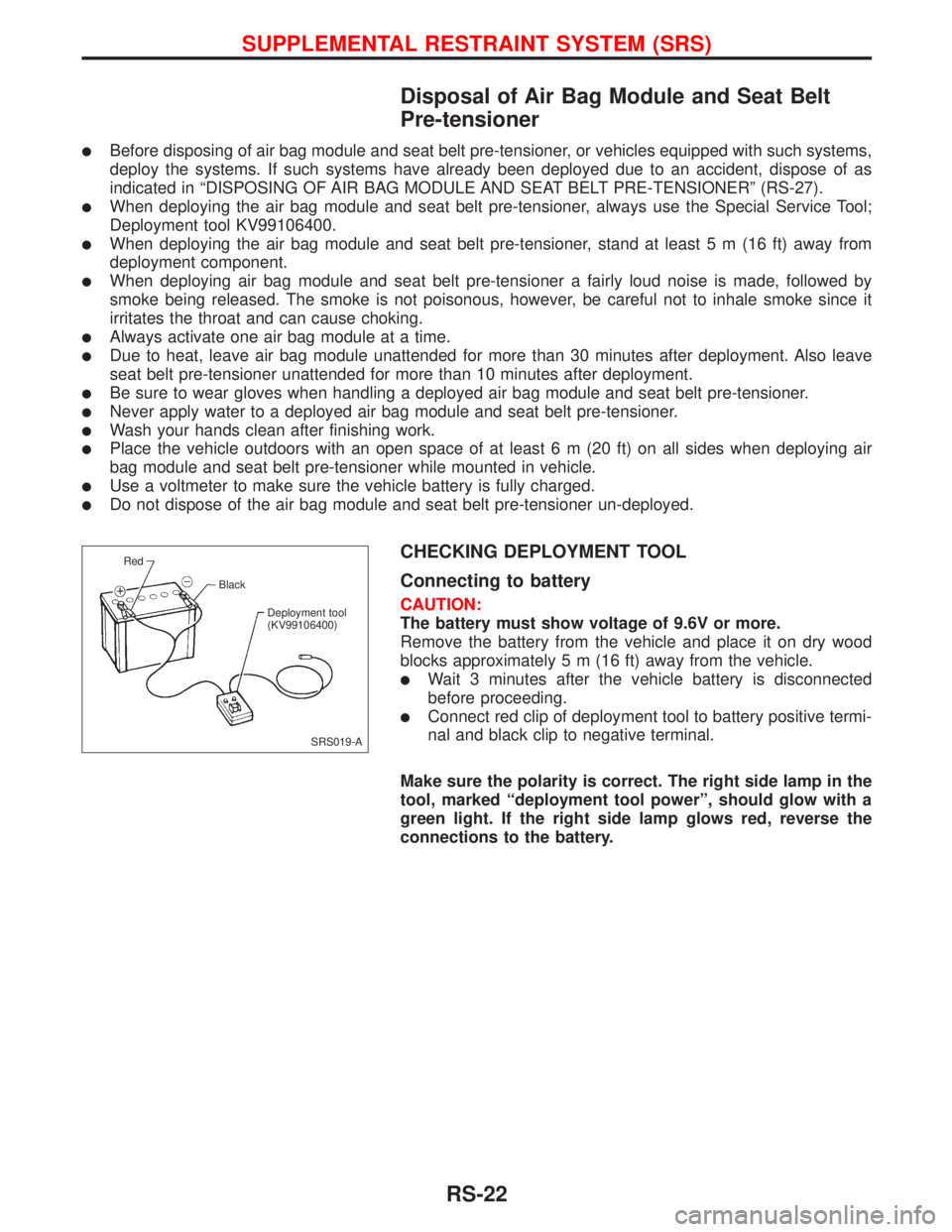
CHECKING DEPLOYMENT TOOL
Connecting to battery
CAUTION:
The battery must show voltage of 9.6V or more.
Remove the battery from the vehicle and place it on dry wood
blocks approximately 5 m (16 ft) away from the vehicle.
lWait 3 minutes after the vehicle battery is disconnected
before proceeding.
lConnect red clip of deployment tool to battery positive termi-
nal and black clip to negative terminal.
Make sure the polarity is correct. The right side lamp in the
tool, marked ªdeployment tool powerº, should glow with a
green light. If the right side lamp glows red, reverse the
connections to the battery.
SRS019-A Red
Black
Deployment tool
(KV99106400)
SUPPLEMENTAL RESTRAINT SYSTEM (SRS)
RS-22