1999 NISSAN PRIMERA door lock
[x] Cancel search: door lockPage 221 of 2267
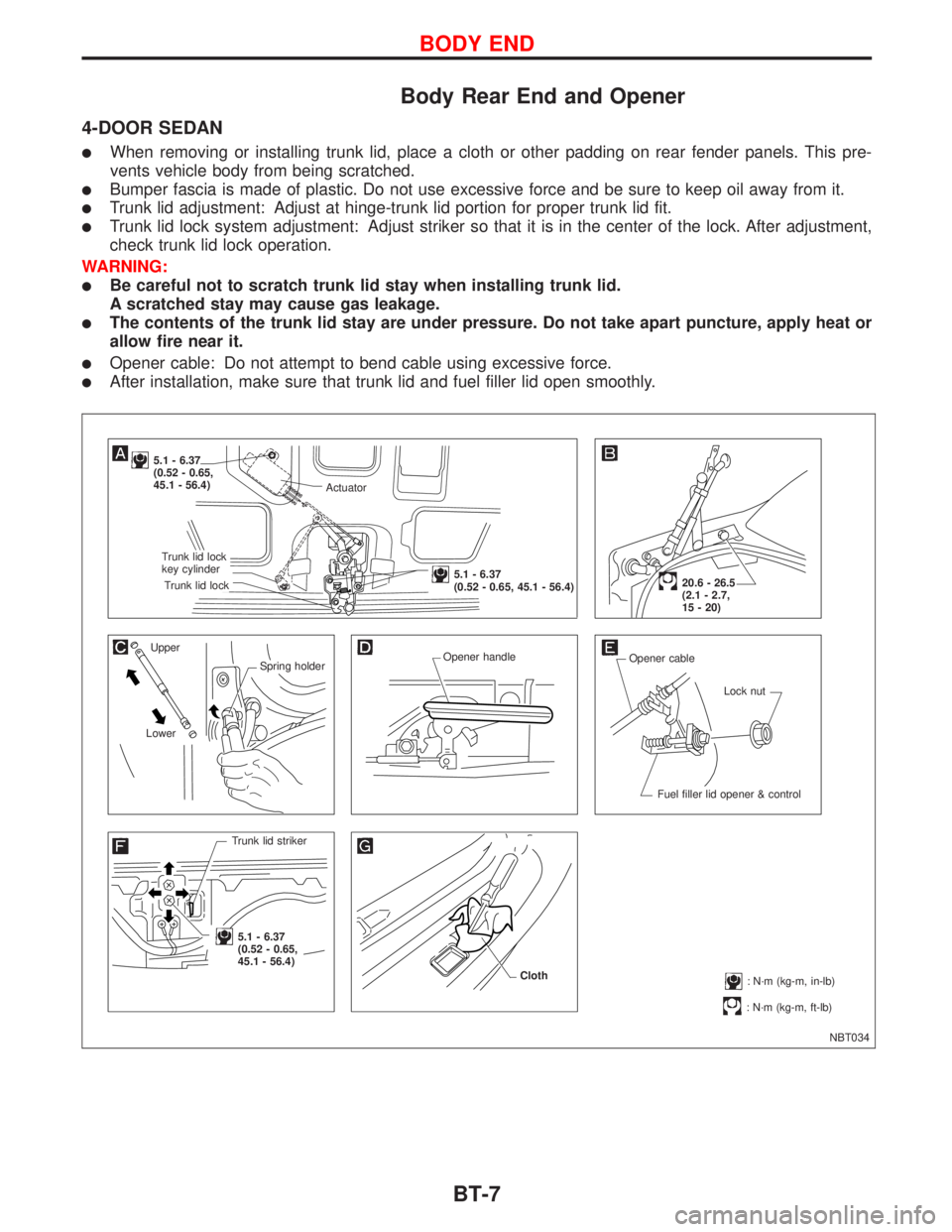
Body Rear End and Opener
4-DOOR SEDAN
lWhen removing or installing trunk lid, place a cloth or other padding on rear fender panels. This pre-
vents vehicle body from being scratched.
lBumper fascia is made of plastic. Do not use excessive force and be sure to keep oil away from it.
lTrunk lid adjustment: Adjust at hinge-trunk lid portion for proper trunk lid fit.
lTrunk lid lock system adjustment: Adjust striker so that it is in the center of the lock. After adjustment,
check trunk lid lock operation.
WARNING:
lBe careful not to scratch trunk lid stay when installing trunk lid.
A scratched stay may cause gas leakage.
lThe contents of the trunk lid stay are under pressure. Do not take apart puncture, apply heat or
allow fire near it.
lOpener cable: Do not attempt to bend cable using excessive force.
lAfter installation, make sure that trunk lid and fuel filler lid open smoothly.
NBT034
5.1 - 6.37
(0.52 - 0.65,
45.1 - 56.4)
Upper
Spring holder
LowerOpener handle
Opener cable
Lock nut
Fuel filler lid opener & control
Trunk lid striker
.5.1 - 6.37
(0.52 - 0.65,
45.1 - 56.4)
: N´m (kg-m, ft-lb)
20.6 - 26.5
(2.1 - 2.7,
15 - 20)
: N´m (kg-m, in-lb) Cloth
Actuator
.Trunk lid lock
key cylinder
.Trunk lid lock
.5.1 - 6.37
(0.52 - 0.65, 45.1 - 56.4)
BODY END
BT-7
Page 223 of 2267
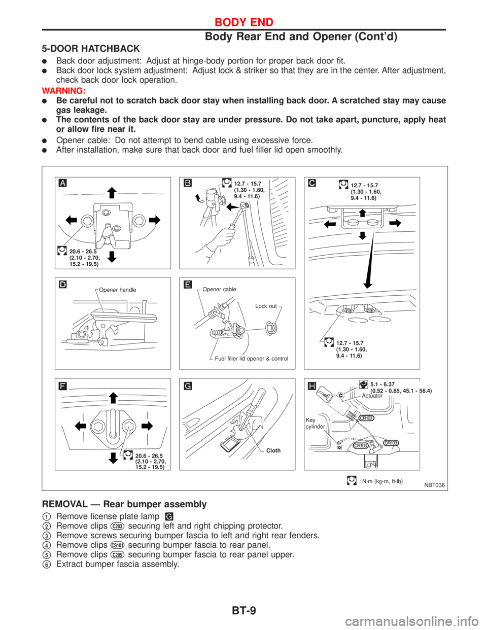
5-DOOR HATCHBACK
lBack door adjustment: Adjust at hinge-body portion for proper back door fit.
lBack door lock system adjustment: Adjust lock & striker so that they are in the center. After adjustment,
check back door lock operation.
WARNING:
lBe careful not to scratch back door stay when installing back door. A scratched stay may cause
gas leakage.
lThe contents of the back door stay are under pressure. Do not take apart, puncture, apply heat
or allow fire near it.
lOpener cable: Do not attempt to bend cable using excessive force.
lAfter installation, make sure that back door and fuel filler lid open smoothly.
REMOVAL Ð Rear bumper assembly
p1Remove license plate lamp
p2Remove clipsC203securing left and right chipping protector.
p3Remove screws securing bumper fascia to left and right rear fenders.
p4Remove clipsCS101securing bumper fascia to rear panel.
p5Remove clipsC205securing bumper fascia to rear panel upper.
p6Extract bumper fascia assembly.
NBT036 Opener handleOpener cable
Lock nut
Fuel filler lid opener & control
20.6 - 26.5
(2.10 - 2.70,
15.2 - 19.5)
12.7 - 15.7
(1.30 - 1.60,
9.4 - 11.6)12.7 - 15.7
(1.30 - 1.60,
9.4 - 11.6)
12.7 - 15.7
(1.30 - 1.60,
9.4 - 11.6)
20.6 - 26.5
(2.10 - 2.70,
15.2 - 19.5)
: N´m (kg-m, ft-lb) Cloth
.5.1 - 6.37
(0.52 - 0.65, 45.1 - 56.4)
Actuator
Key
cylinder
BODY END
Body Rear End and Opener (Cont'd)
BT-9
Page 225 of 2267
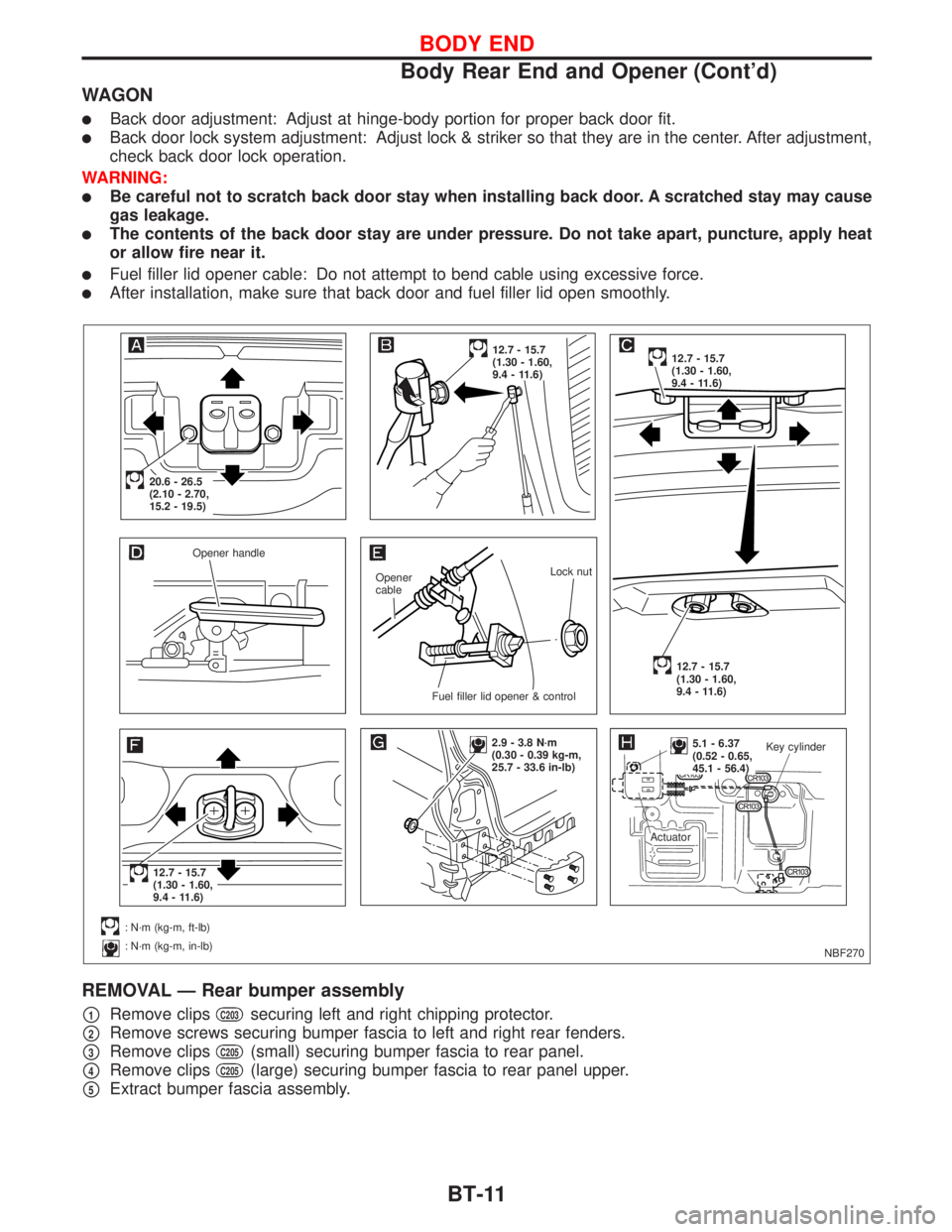
WAGON
lBack door adjustment: Adjust at hinge-body portion for proper back door fit.
lBack door lock system adjustment: Adjust lock & striker so that they are in the center. After adjustment,
check back door lock operation.
WARNING:
lBe careful not to scratch back door stay when installing back door. A scratched stay may cause
gas leakage.
lThe contents of the back door stay are under pressure. Do not take apart, puncture, apply heat
or allow fire near it.
lFuel filler lid opener cable: Do not attempt to bend cable using excessive force.
lAfter installation, make sure that back door and fuel filler lid open smoothly.
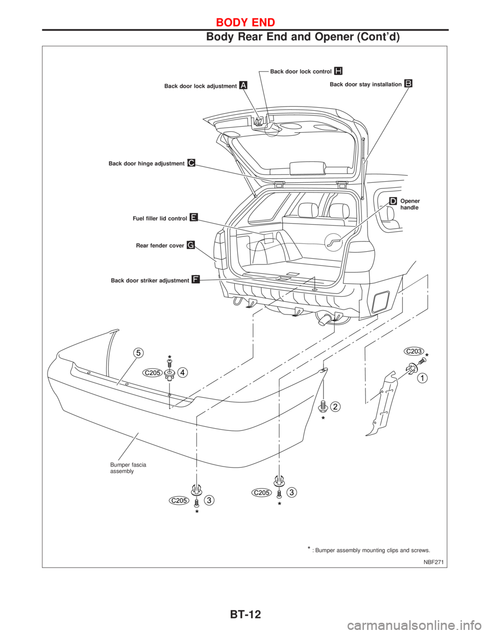
REMOVAL Ð Rear bumper assembly
p1Remove clipsC203securing left and right chipping protector.
p2Remove screws securing bumper fascia to left and right rear fenders.
p3Remove clipsC205(small) securing bumper fascia to rear panel.
p4Remove clipsC205(large) securing bumper fascia to rear panel upper.
p5Extract bumper fascia assembly.
NBF270 Opener handle
Opener
cableLock nut
.Fuel filler lid opener & control
.20.6 - 26.5
(2.10 - 2.70,
15.2 - 19.5)
12.7 - 15.7
(1.30 - 1.60,
9.4 - 11.6)12.7 - 15.7
(1.30 - 1.60,
9.4 - 11.6)
12.7 - 15.7
(1.30 - 1.60,
9.4 - 11.6)
.12.7 - 15.7
(1.30 - 1.60,
9.4 - 11.6)
: N´m (kg-m, ft-lb)
: N´m (kg-m, in-lb)
2.9 - 3.8 N´m
(0.30 - 0.39 kg-m,
25.7 - 33.6 in-lb)..5.1 - 6.37
(0.52 - 0.65,
45.1 - 56.4)Key cylinder
Actuator
BODY END
Body Rear End and Opener (Cont'd)
BT-11
Page 226 of 2267
NBF271 Back door lock adjustment
Back door hinge adjustment
Back door stay installation
Opener
handle
Fuel filler lid control
Back door striker adjustment
*: Bumper assembly mounting clips and screws. Bumper fascia
assemblyRear fender cover
Back door lock control
BODY END
Body Rear End and Opener (Cont'd)
BT-12
Page 227 of 2267
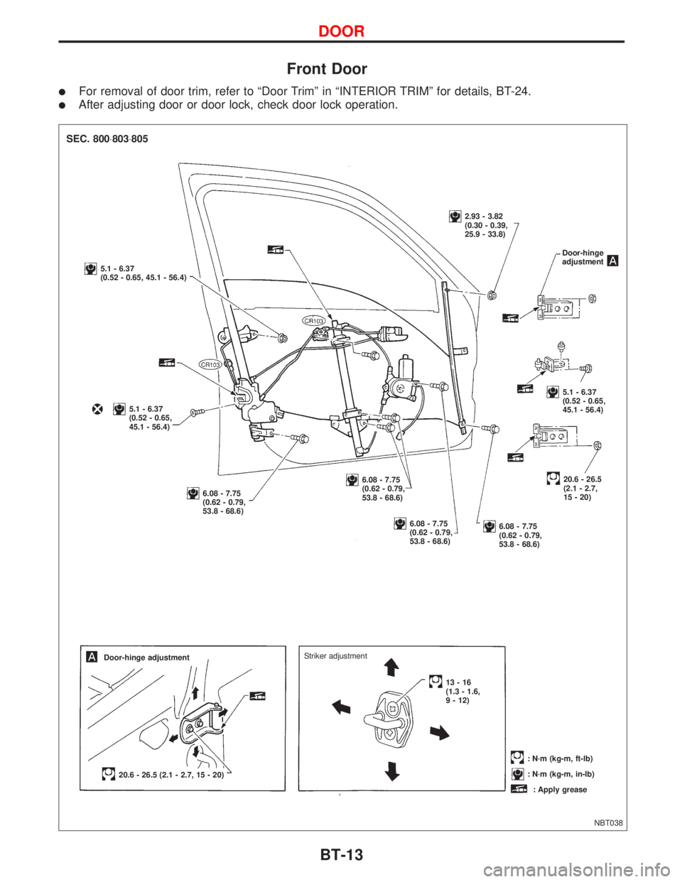
Front Door
lFor removal of door trim, refer to ªDoor Trimº in ªINTERIOR TRIMº for details, BT-24.
lAfter adjusting door or door lock, check door lock operation.
NBT038
SEC. 800×803×805
5.1 - 6.37
(0.52 - 0.65, 45.1 - 56.4)
5.1 - 6.37
(0.52 - 0.65,
45.1 - 56.4)
6.08 - 7.75
(0.62 - 0.79,
53.8 - 68.6)
6.08 - 7.75
(0.62 - 0.79,
53.8 - 68.6)
6.08 - 7.75
(0.62 - 0.79,
53.8 - 68.6)6.08 - 7.75
(0.62 - 0.79,
53.8 - 68.6)
20.6 - 26.5
(2.1 - 2.7,
15 - 20)
5.1 - 6.37
(0.52 - 0.65,
45.1 - 56.4)
2.93 - 3.82
(0.30 - 0.39,
25.9 - 33.8)
Door-hinge adjustment
20.6 - 26.5 (2.1 - 2.7, 15 - 20)
: N´m (kg-m, ft-lb)
: N´m (kg-m, in-lb)
: Apply grease Striker adjustment
13-16
(1.3 - 1.6,
9 - 12)Door-hinge
adjustment
DOOR
BT-13
Page 1134 of 2267
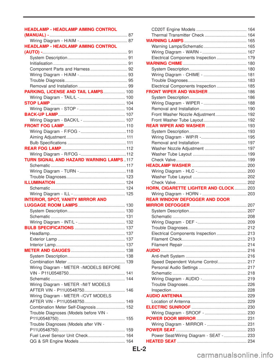
HEADLAMP - HEADLAMP AIMING CONTROL
(MANUAL) -................................................................. 87
Wiring Diagram - H/AIM - ........................................ 87
HEADLAMP - HEADLAMP AIMING CONTROL
(AUTO) -....................................................................... 91
System Description .................................................. 91
Initialisation .............................................................. 91
Component Parts and Harness ............................... 92
Wiring Diagram - H/AIM - ........................................ 93
Trouble Diagnosis .................................................... 95
Removal and Installation ......................................... 99
PARKING, LICENSE AND TAIL LAMPS.................. 100
Wiring Diagram - TAIL/L - ...................................... 100
STOP LAMP.............................................................. 104
Wiring Diagram - STOP - ...................................... 104
BACK-UP LAMP........................................................ 107
Wiring Diagram - BACK/L - ................................... 107
FRONT FOG LAMP.................................................... 110
Wiring Diagram - F/FOG - ...................................... 110
Aiming Adjustment .................................................. 111
Bulb Specifications ................................................. 111
REAR FOG LAMP...................................................... 112
Wiring Diagram - R/FOG -...................................... 112
TURN SIGNAL AND HAZARD WARNING LAMPS.. 117
Schematic ............................................................... 117
Wiring Diagram - TURN - ....................................... 118
Trouble Diagnoses................................................. 123
ILLUMINATION.......................................................... 124
Schematic .............................................................. 124
Wiring Diagram - ILL - ........................................... 125
INTERIOR, SPOT, VANITY MIRROR AND
LUGGAGE ROOM LAMPS....................................... 130
System Description ................................................ 130
Schematic .............................................................. 131
Wiring Diagram - INT/L - ....................................... 132
BULB SPECIFICATIONS.......................................... 137
Headlamp............................................................... 137
Exterior Lamp ........................................................ 137
Interior Lamp.......................................................... 137
METER AND GAUGES............................................. 138
System Description ................................................ 138
Combination Meter ................................................ 139
Wiring Diagram - METER -/MODELS BEFORE
VIN - P11U0548750............................................... 141
Schematic .............................................................. 144
Wiring Diagram - METER -/M/T MODELS
AFTER VIN - P11U0548750.................................. 146
Wiring Diagram - METER -/CVT MODELS
AFTER VIN - P11U0548750.................................. 149
Combination Meter Self-Diagnosis ........................ 152
Trouble Diagnoses (Models before VIN -
P11U0548750) ....................................................... 155
Trouble Diagnoses (Models after VIN -
P11U0548750) ....................................................... 159
Fuel Level Sensor Unit Check............................... 164
QG & SR Engine Models ...................................... 164CD20T Engine Models .......................................... 164
Thermal Transmitter Check ................................... 164
WARNING LAMPS.................................................... 165
Warning Lamps/Schematic .................................... 165
Wiring Diagram - WARN - ..................................... 167
Electrical Components Inspection ......................... 179
WARNING CHIME..................................................... 180
System Description ................................................ 180
Wiring Diagram - CHIME - .................................... 181
Trouble Diagnoses................................................. 183
Electrical Components Inspection ......................... 185
FRONT WIPER AND WASHER................................ 186
System Description ................................................ 186
Wiring Diagram - WIPER - .................................... 188
Removal and Installation ....................................... 190
Front Washer Nozzle Adjustment .......................... 192
Front Washer Tube Layout .................................... 192
REAR WIPER AND WASHER.................................. 193
System Description ................................................ 193
Wiring Diagram - WIP/R -...................................... 195
Removal and Installation ....................................... 197
Washer Nozzle Adjustment ................................... 197
Washer Tube Layout ............................................. 199
Check Valve ........................................................... 199
HEADLAMP WASHER.............................................. 200
Wiring Diagram - HLC - ......................................... 200
Washer Tube Layout ............................................. 202
Check Valve ........................................................... 202
HORN, CIGARETTE LIGHTER AND CLOCK.......... 203
Wiring Diagram - HORN - ..................................... 203
REAR WINDOW DEFOGGER AND DOOR
MIRROR DEFOGGER............................................... 207
System Description ................................................ 207
Schematic .............................................................. 208
Wiring Diagram - DEF - ......................................... 209
Trouble Diagnoses................................................. 212
Electrical Components Inspection ......................... 213
Filament Check ...................................................... 213
Filament Repair ..................................................... 214
AUDIO........................................................................ 216
Anti-theft System ................................................... 216
Speed Dependent Volume Control ........................ 217
Personal Audio Settings ........................................ 217
Schematic .............................................................. 218
Wiring Diagram - AUDIO - ..................................... 219
Trouble Diagnoses................................................. 226
Inspection............................................................... 228
AUDIO ANTENNA..................................................... 229
Location of Antenna ............................................... 229
ELECTRIC SUNROOF.............................................. 230
Wiring Diagram - SROOF - ................................... 230
POWER DOOR MIRROR.......................................... 231
Wiring Diagram - MIRROR - ................................. 231
POWER SEAT........................................................... 233
Power Seat/Wiring Diagram - SEAT - ................... 233
HEATED SEAT.......................................................... 234
EL-2
Page 1135 of 2267
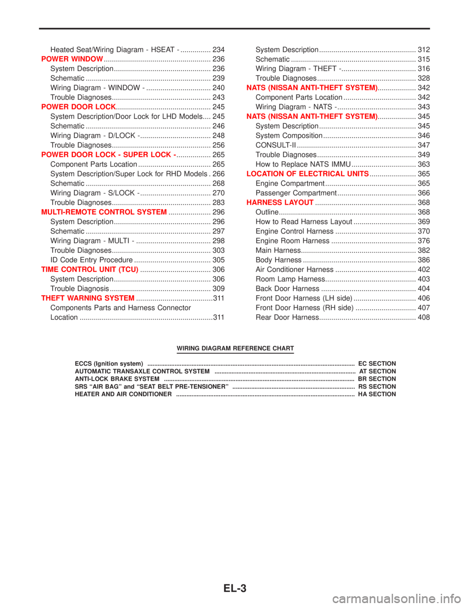
Heated Seat/Wiring Diagram - HSEAT - ............... 234
POWER WINDOW..................................................... 236
System Description ................................................ 236
Schematic .............................................................. 239
Wiring Diagram - WINDOW - ................................ 240
Trouble Diagnoses................................................. 243
POWER DOOR LOCK............................................... 245
System Description/Door Lock for LHD Models.... 245
Schematic .............................................................. 246
Wiring Diagram - D/LOCK -................................... 248
Trouble Diagnoses................................................. 256
POWER DOOR LOCK - SUPER LOCK -................. 265
Component Parts Location .................................... 265
System Description/Super Lock for RHD Models . 266
Schematic .............................................................. 268
Wiring Diagram - S/LOCK - ................................... 270
Trouble Diagnoses................................................. 283
MULTI-REMOTE CONTROL SYSTEM..................... 296
System Description ................................................ 296
Schematic .............................................................. 297
Wiring Diagram - MULTI - ..................................... 298
Trouble Diagnoses................................................. 303
ID Code Entry Procedure ...................................... 305
TIME CONTROL UNIT (TCU)................................... 306
System Description ................................................ 306
Trouble Diagnosis .................................................. 309
THEFT WARNING SYSTEM...................................... 311
Components Parts and Harness Connector
Location .................................................................. 311System Description ................................................ 312
Schematic .............................................................. 315
Wiring Diagram - THEFT -..................................... 316
Trouble Diagnoses................................................. 328
NATS (NISSAN ANTI-THEFT SYSTEM)................... 342
Component Parts Location .................................... 342
Wiring Diagram - NATS -....................................... 343
NATS (NISSAN ANTI-THEFT SYSTEM)................... 345
System Description ................................................ 345
System Composition .............................................. 346
CONSULT-II ........................................................... 347
Trouble Diagnoses................................................. 349
How to Replace NATS IMMU ................................ 363
LOCATION OF ELECTRICAL UNITS....................... 365
Engine Compartment ............................................. 365
Passenger Compartment ....................................... 366
HARNESS LAYOUT.................................................. 368
Outline.................................................................... 368
How to Read Harness Layout ............................... 369
Engine Control Harness ........................................ 370
Engine Room Harness .......................................... 376
Main Harness......................................................... 382
Body Harness ........................................................ 386
Air Conditioner Harness ........................................ 402
Room Lamp Harness............................................. 403
Back Door Harness ............................................... 404
Front Door Harness (LH side) ............................... 406
Front Door Harness (RH side) .............................. 407
Rear Door Harness................................................ 408
WIRING DIAGRAM REFERENCE CHART
ECCS (Ignition system) .......................................................................................................................... EC SECTION
AUTOMATIC TRANSAXLE CONTROL SYSTEM ................................................................................... AT SECTION
ANTI-LOCK BRAKE SYSTEM ................................................................................................................ BR SECTION
SRS“AIR BAG”and“SEAT BELT PRE-TENSIONER”........................................................................ RS SECTION
HEATER AND AIR CONDITIONER ......................................................................................................... HA SECTION
EL-3
Page 1155 of 2267
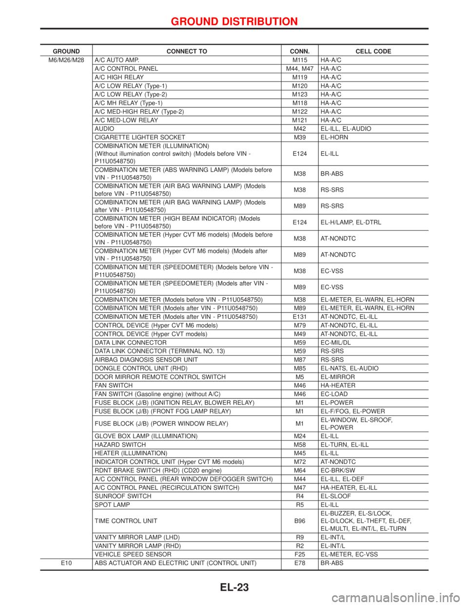
GROUND CONNECT TO CONN. CELL CODE
M6/M26/M28 A/C AUTO AMP. M115 HA-A/C
A/C CONTROL PANEL M44, M47 HA-A/C
A/C HIGH RELAY M119 HA-A/C
A/C LOW RELAY (Type-1) M120 HA-A/C
A/C LOW RELAY (Type-2) M123 HA-A/C
A/C MH RELAY (Type-1) M118 HA-A/C
A/C MED-HIGH RELAY (Type-2) M122 HA-A/C
A/C MED-LOW RELAY M121 HA-A/C
AUDIO M42 EL-ILL, EL-AUDIO
CIGARETTE LIGHTER SOCKET M39 EL-HORN
COMBINATION METER (ILLUMINATION)
(Without illumination control switch) (Models before VIN -
P11U0548750)E124 EL-ILL
COMBINATION METER (ABS WARNING LAMP) (Models before
VIN - P11U0548750)M38 BR-ABS
COMBINATION METER (AIR BAG WARNING LAMP) (Models
before VIN - P11U0548750)M38 RS-SRS
COMBINATION METER (AIR BAG WARNING LAMP) (Models
after VIN - P11U0548750)M89 RS-SRS
COMBINATION METER (HIGH BEAM INDICATOR) (Models
before VIN - P11U0548750)E124 EL-H/LAMP, EL-DTRL
COMBINATION METER (Hyper CVT M6 models) (Models before
VIN - P11U0548750)M38 AT-NONDTC
COMBINATION METER (Hyper CVT M6 models) (Models after
VIN - P11U0548750)M89 AT-NONDTC
COMBINATION METER (SPEEDOMETER) (Models before VIN -
P11U0548750)M38 EC-VSS
COMBINATION METER (SPEEDOMETER) (Models after VIN -
P11U0548750)M89 EC-VSS
COMBINATION METER (Models before VIN - P11U0548750) M38 EL-METER, EL-WARN, EL-HORN
COMBINATION METER (Models after VIN - P11U0548750) M89 EL-METER, EL-WARN, EL-HORN
COMBINATION METER (Models after VIN - P11U0548750) E131 AT-NONDTC, EL-ILL
CONTROL DEVICE (Hyper CVT M6 models) M79 AT-NONDTC, EL-ILL
CONTROL DEVICE (Hyper CVT models) M49 AT-NONDTC, EL-ILL
DATA LINK CONNECTOR M59 EC-MIL/DL
DATA LINK CONNECTOR (TERMINAL NO. 13) M59 RS-SRS
AIRBAG DIAGNOSIS SENSOR UNIT M87 RS-SRS
DONGLE CONTROL UNIT (RHD) M85 EL-NATS, EL-AUDIO
DOOR MIRROR REMOTE CONTROL SWITCH M5 EL-MIRROR
FAN SWITCH M46 HA-HEATER
FAN SWITCH (Gasoline engine) (without A/C) M46 EC-LOAD
FUSE BLOCK (J/B) (IGNITION RELAY, BLOWER RELAY) M1 EL-POWER
FUSE BLOCK (J/B) (FRONT FOG LAMP RELAY) M1 EL-F/FOG, EL-POWER
FUSE BLOCK (J/B) (POWER WINDOW RELAY) M1EL-WINDOW, EL-SROOF,
EL-POWER
GLOVE BOX LAMP (ILLUMINATION) M24 EL-ILL
HAZARD SWITCH M58 EL-TURN, EL-ILL
HEATER (ILLUMINATION) M45 EL-ILL
INDICATOR CONTROL UNIT (Hyper CVT M6 models) M72 AT-NONDTC
RDNT BRAKE SWITCH (RHD) (CD20 engine) M64 EC-BRK/SW
A/C CONTROL PANEL (REAR WINDOW DEFOGGER SWITCH) M44 EL-ILL, EL-DEF
A/C CONTROL PANEL (RECIRCULATION SWITCH) M47 HA-HEATER, EL-ILL
SUNROOF SWITCH R4 EL-SLOOF
SPOT LAMP R5 EL-ILL
TIME CONTROL UNIT B96EL-BUZZER, EL-S/LOCK,
EL-D/LOCK, EL-THEFT, EL-DEF,
EL-MULTI, EL-INT/L, EL-TURN
VANITY MIRROR LAMP (LHD) R9 EL-INT/L
VANITY MIRROR LAMP (RHD) R2 EL-INT/L
VEHICLE SPEED SENSOR F25 EL-METER, EC-VSS
E10 ABS ACTUATOR AND ELECTRIC UNIT (CONTROL UNIT) E78 BR-ABS
GROUND DISTRIBUTION
EL-23