1999 NISSAN PRIMERA sensor
[x] Cancel search: sensorPage 1830 of 2267
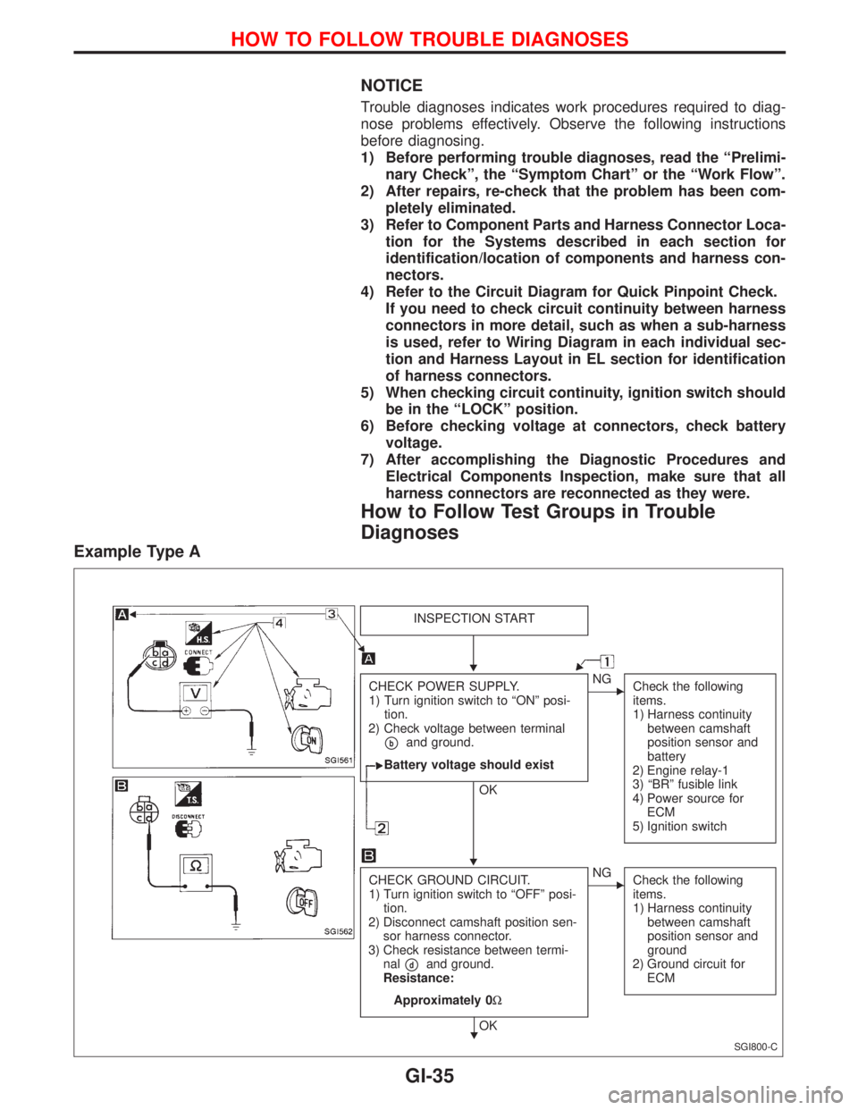
NOTICE
Trouble diagnoses indicates work procedures required to diag-
nose problems effectively. Observe the following instructions
before diagnosing.
1) Before performing trouble diagnoses, read the ªPrelimi-
nary Checkº, the ªSymptom Chartº or the ªWork Flowº.
2) After repairs, re-check that the problem has been com-
pletely eliminated.
3) Refer to Component Parts and Harness Connector Loca-
tion for the Systems described in each section for
identification/location of components and harness con-
nectors.
4) Refer to the Circuit Diagram for Quick Pinpoint Check.
If you need to check circuit continuity between harness
connectors in more detail, such as when a sub-harness
is used, refer to Wiring Diagram in each individual sec-
tion and Harness Layout in EL section for identification
of harness connectors.
5) When checking circuit continuity, ignition switch should
be in the ªLOCKº position.
6) Before checking voltage at connectors, check battery
voltage.
7) After accomplishing the Diagnostic Procedures and
Electrical Components Inspection, make sure that all
harness connectors are reconnected as they were.
How to Follow Test Groups in Trouble
Diagnoses
Example Type A
SGI800-C
INSPECTION START
CHECK POWER SUPPLY.
1) Turn ignition switch to ªONº posi-
tion.
2) Check voltage between terminal
pband ground.
Battery voltage should exist
OK
ENG
Check the following
items.
1) Harness continuity
between camshaft
position sensor and
battery
2) Engine relay-1
3) ªBRº fusible link
4) Power source for
ECM
5) Ignition switch
CHECK GROUND CIRCUIT.
1) Turn ignition switch to ªOFFº posi-
tion.
2) Disconnect camshaft position sen-
sor harness connector.
3) Check resistance between termi-
nal
pdand ground.
Resistance:
Approximately 0W
OK
ENG
Check the following
items.
1) Harness continuity
between camshaft
position sensor and
ground
2) Ground circuit for
ECM
H
H
H
HOW TO FOLLOW TROUBLE DIAGNOSES
GI-35
Page 1835 of 2267
NOTE:
lThe CONSULT-II must be used in conjunction with a program card.
CONSULT-II does not require loading (Initialisation) procedure.
lBe sure the CONSULT-II is turned off before installing or removing a program card.
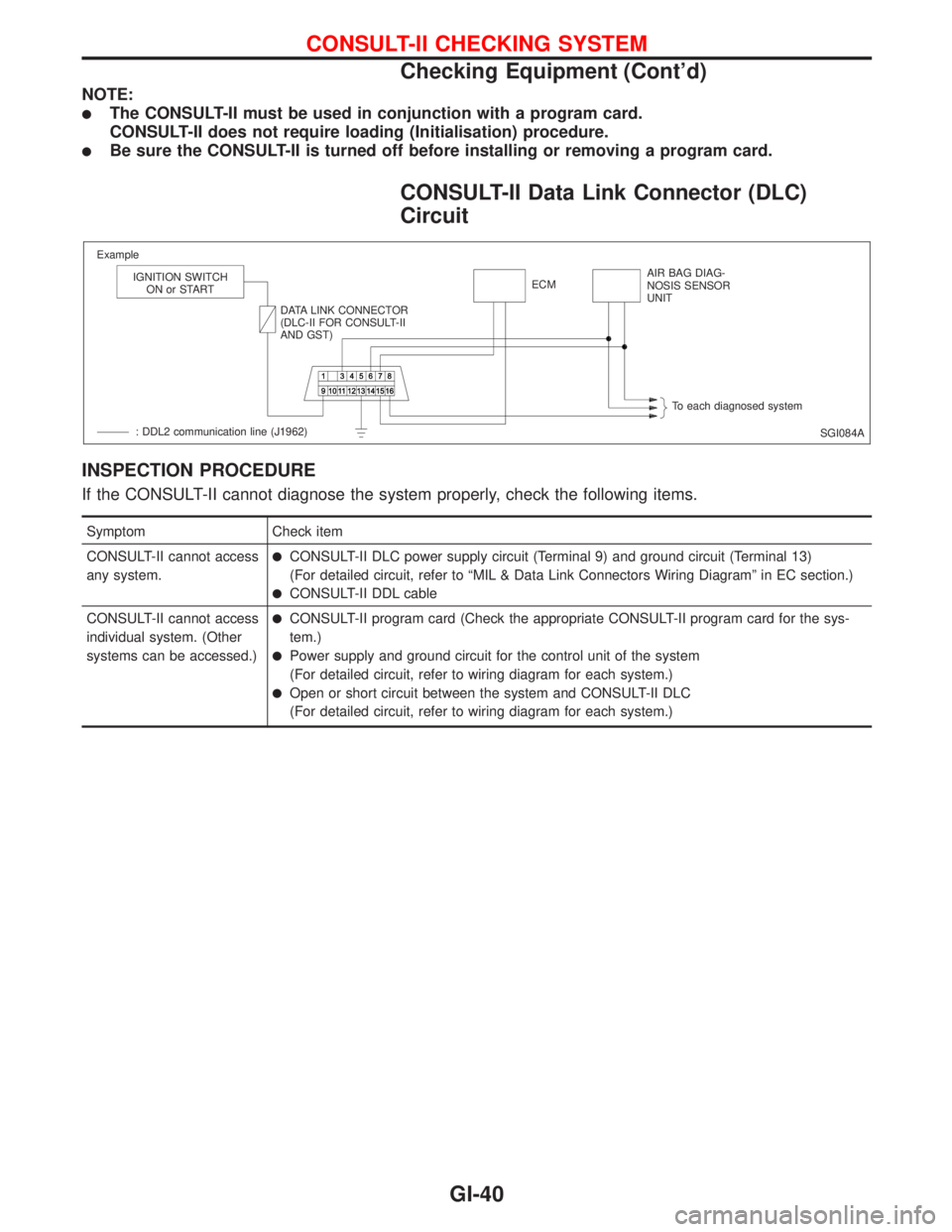
CONSULT-II Data Link Connector (DLC)
Circuit
INSPECTION PROCEDURE
If the CONSULT-II cannot diagnose the system properly, check the following items.
Symptom Check item
CONSULT-II cannot access
any system.
lCONSULT-II DLC power supply circuit (Terminal 9) and ground circuit (Terminal 13)
(For detailed circuit, refer to ªMIL & Data Link Connectors Wiring Diagramº in EC section.)
lCONSULT-II DDL cable
CONSULT-II cannot access
individual system. (Other
systems can be accessed.)
lCONSULT-II program card (Check the appropriate CONSULT-II program card for the sys-
tem.)
lPower supply and ground circuit for the control unit of the system
(For detailed circuit, refer to wiring diagram for each system.)
lOpen or short circuit between the system and CONSULT-II DLC
(For detailed circuit, refer to wiring diagram for each system.)
SGI084A Example
IGNITION SWITCH
ON or START
DATA LINK CONNECTOR
(DLC-II FOR CONSULT-II
AND GST)ECMAIR BAG DIAG-
NOSIS SENSOR
UNIT
To each diagnosed system
: DDL2 communication line (J1962)
CONSULT-II CHECKING SYSTEM
Checking Equipment (Cont'd)
GI-40
Page 1846 of 2267
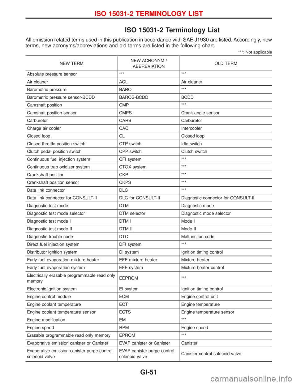
ISO 15031-2 Terminology List
All emission related terms used in this publication in accordance with SAE J1930 are listed. Accordingly, new
terms, new acronyms/abbreviations and old terms are listed in the following chart.
***: Not applicable
NEW TERMNEW ACRONYM /
ABBREVIATIONOLD TERM
Absolute pressure sensor *** ***
Air cleaner ACL Air cleaner
Barometric pressure BARO ***
Barometric pressure sensor-BCDD BAROS-BCDD BCDD
Camshaft position CMP ***
Camshaft position sensor CMPS Crank angle sensor
Carburetor CARB Carburetor
Charge air cooler CAC Intercooler
Closed loop CL Closed loop
Closed throttle position switch CTP switch Idle switch
Clutch pedal position switch CPP switch Clutch switch
Continuous fuel injection system CFI system ***
Continuous trap oxidizer system CTOX system ***
Crankshaft position CKP ***
Crankshaft position sensor CKPS ***
Data link connector DLC ***
Data link connector for CONSULT-II DLC for CONSULT-II Diagnostic connector for CONSULT-II
Diagnostic test mode DTM Diagnostic mode
Diagnostic test mode selector DTM selector Diagnostic mode selector
Diagnostic test mode I DTM I Mode I
Diagnostic test mode II DTM II Mode II
Diagnostic trouble code DTC Malfunction code
Direct fuel injection system DFI system ***
Distributor ignition system DI system Ignition timing control
Early fuel evaporation-mixture heater EFE-mixture heater Mixture heater
Early fuel evaporation system EFE system Mixture heater control
Electrically erasable programmable read only
memoryEEPROM ***
Electronic ignition system EI system Ignition timing control
Engine control module ECM Engine control unit
Engine coolant temperature ECT Engine temperature
Engine coolant temperature sensor ECTS Engine temperature sensor
Engine modification EM ***
Engine speed RPM Engine speed
Erasable programmable read only memory EPROM ***
Evaporative emission canister or Canister EVAP canister or Canister Canister
Evaporative emission canister purge control
solenoid valveEVAP canister purge control
solenoid valveCanister control solenoid valve
ISO 15031-2 TERMINOLOGY LIST
GI-51
Page 1847 of 2267
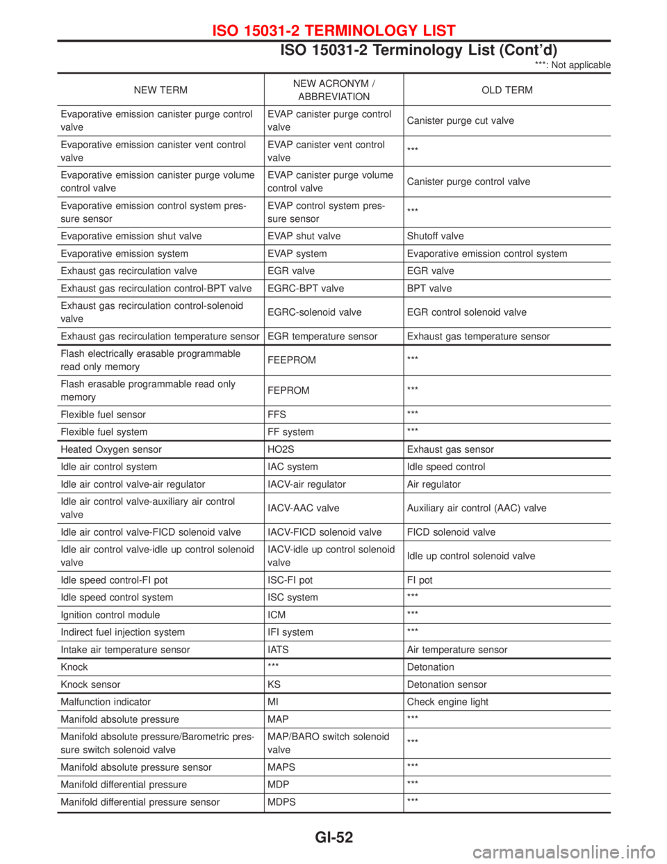
***: Not applicable
NEW TERMNEW ACRONYM /
ABBREVIATIONOLD TERM
Evaporative emission canister purge control
valveEVAP canister purge control
valveCanister purge cut valve
Evaporative emission canister vent control
valveEVAP canister vent control
valve***
Evaporative emission canister purge volume
control valveEVAP canister purge volume
control valveCanister purge control valve
Evaporative emission control system pres-
sure sensorEVAP control system pres-
sure sensor***
Evaporative emission shut valve EVAP shut valve Shutoff valve
Evaporative emission system EVAP system Evaporative emission control system
Exhaust gas recirculation valve EGR valve EGR valve
Exhaust gas recirculation control-BPT valve EGRC-BPT valve BPT valve
Exhaust gas recirculation control-solenoid
valveEGRC-solenoid valve EGR control solenoid valve
Exhaust gas recirculation temperature sensor EGR temperature sensor Exhaust gas temperature sensor
Flash electrically erasable programmable
read only memoryFEEPROM ***
Flash erasable programmable read only
memoryFEPROM ***
Flexible fuel sensor FFS ***
Flexible fuel system FF system ***
Heated Oxygen sensor HO2S Exhaust gas sensor
Idle air control system IAC system Idle speed control
Idle air control valve-air regulator IACV-air regulator Air regulator
Idle air control valve-auxiliary air control
valveIACV-AAC valve Auxiliary air control (AAC) valve
Idle air control valve-FICD solenoid valve IACV-FICD solenoid valve FICD solenoid valve
Idle air control valve-idle up control solenoid
valveIACV-idle up control solenoid
valveIdle up control solenoid valve
Idle speed control-FI pot ISC-FI pot FI pot
Idle speed control system ISC system ***
Ignition control module ICM ***
Indirect fuel injection system IFI system ***
Intake air temperature sensor IATS Air temperature sensor
Knock *** Detonation
Knock sensor KS Detonation sensor
Malfunction indicator MI Check engine light
Manifold absolute pressure MAP ***
Manifold absolute pressure/Barometric pres-
sure switch solenoid valveMAP/BARO switch solenoid
valve***
Manifold absolute pressure sensor MAPS ***
Manifold differential pressure MDP ***
Manifold differential pressure sensor MDPS ***
ISO 15031-2 TERMINOLOGY LIST
ISO 15031-2 Terminology List (Cont'd)
GI-52
Page 1848 of 2267
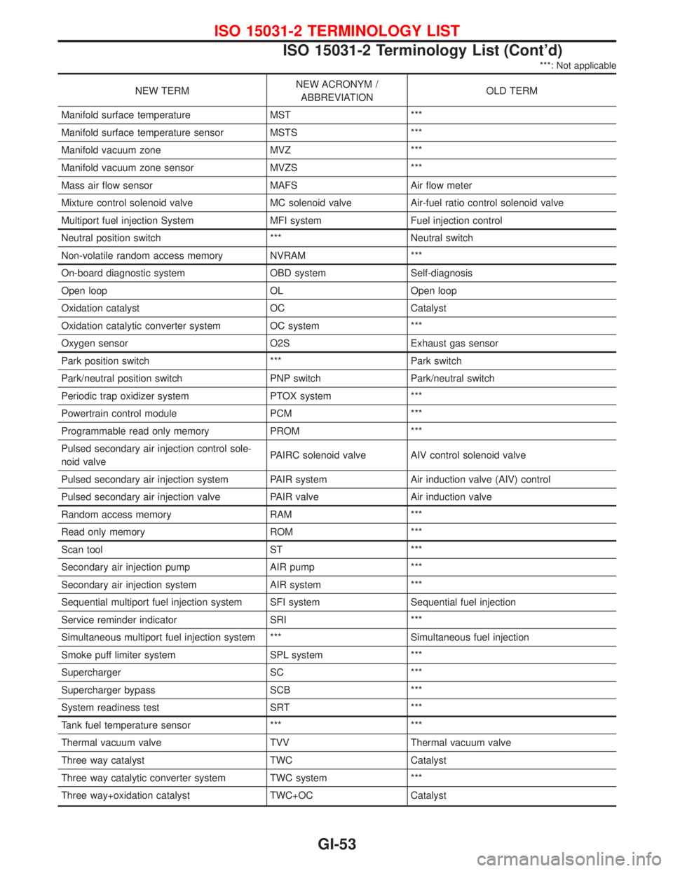
***: Not applicable
NEW TERMNEW ACRONYM /
ABBREVIATIONOLD TERM
Manifold surface temperature MST ***
Manifold surface temperature sensor MSTS ***
Manifold vacuum zone MVZ ***
Manifold vacuum zone sensor MVZS ***
Mass air flow sensor MAFS Air flow meter
Mixture control solenoid valve MC solenoid valve Air-fuel ratio control solenoid valve
Multiport fuel injection System MFI system Fuel injection control
Neutral position switch *** Neutral switch
Non-volatile random access memory NVRAM ***
On-board diagnostic system OBD system Self-diagnosis
Open loop OL Open loop
Oxidation catalyst OC Catalyst
Oxidation catalytic converter system OC system ***
Oxygen sensor O2S Exhaust gas sensor
Park position switch *** Park switch
Park/neutral position switch PNP switch Park/neutral switch
Periodic trap oxidizer system PTOX system ***
Powertrain control module PCM ***
Programmable read only memory PROM ***
Pulsed secondary air injection control sole-
noid valvePAIRC solenoid valve AIV control solenoid valve
Pulsed secondary air injection system PAIR system Air induction valve (AIV) control
Pulsed secondary air injection valve PAIR valve Air induction valve
Random access memory RAM ***
Read only memory ROM ***
Scan tool ST ***
Secondary air injection pump AIR pump ***
Secondary air injection system AIR system ***
Sequential multiport fuel injection system SFI system Sequential fuel injection
Service reminder indicator SRI ***
Simultaneous multiport fuel injection system *** Simultaneous fuel injection
Smoke puff limiter system SPL system ***
Supercharger SC ***
Supercharger bypass SCB ***
System readiness test SRT ***
Tank fuel temperature sensor *** ***
Thermal vacuum valve TVV Thermal vacuum valve
Three way catalyst TWC Catalyst
Three way catalytic converter system TWC system ***
Three way+oxidation catalyst TWC+OC Catalyst
ISO 15031-2 TERMINOLOGY LIST
ISO 15031-2 Terminology List (Cont'd)
GI-53
Page 1849 of 2267

***: Not applicable
NEW TERMNEW ACRONYM /
ABBREVIATIONOLD TERM
Three way + oxidation catalytic converter
systemTWC + OC system ***
Throttle body TB Throttle chamber
SPI body
Throttle body fuel injection system TBI system Fuel injection control
Throttle position TP Throttle position
Throttle position sensor TPS Throttle sensor
Throttle position switch TP switch Throttle switch
Torque converter clutch solenoid valve TCC solenoid valve Lock-up cancel solenoid
Lock-up solenoid
Turbocharger TC Turbocharger
Vacuum cut valve *** Vacuum control valve
Vacuum cut valve bypass valve *** ***
Vehicle speed sensor VSS Vehicle speed sensor
Volume air flow sensor VAFS Air flow meter
Warm up oxidation catalyst WU-OC Catalyst
Warm up oxidation catalytic converter system WU-OC system ***
Warm up three way catalyst WU-TWC Catalyst
Warm up three way catalytic converter sys-
temWU-TWC system ***
Wide open throttle position switch WOTP switch Full switch
ISO 15031-2 TERMINOLOGY LIST
ISO 15031-2 Terminology List (Cont'd)
GI-54
Page 1852 of 2267
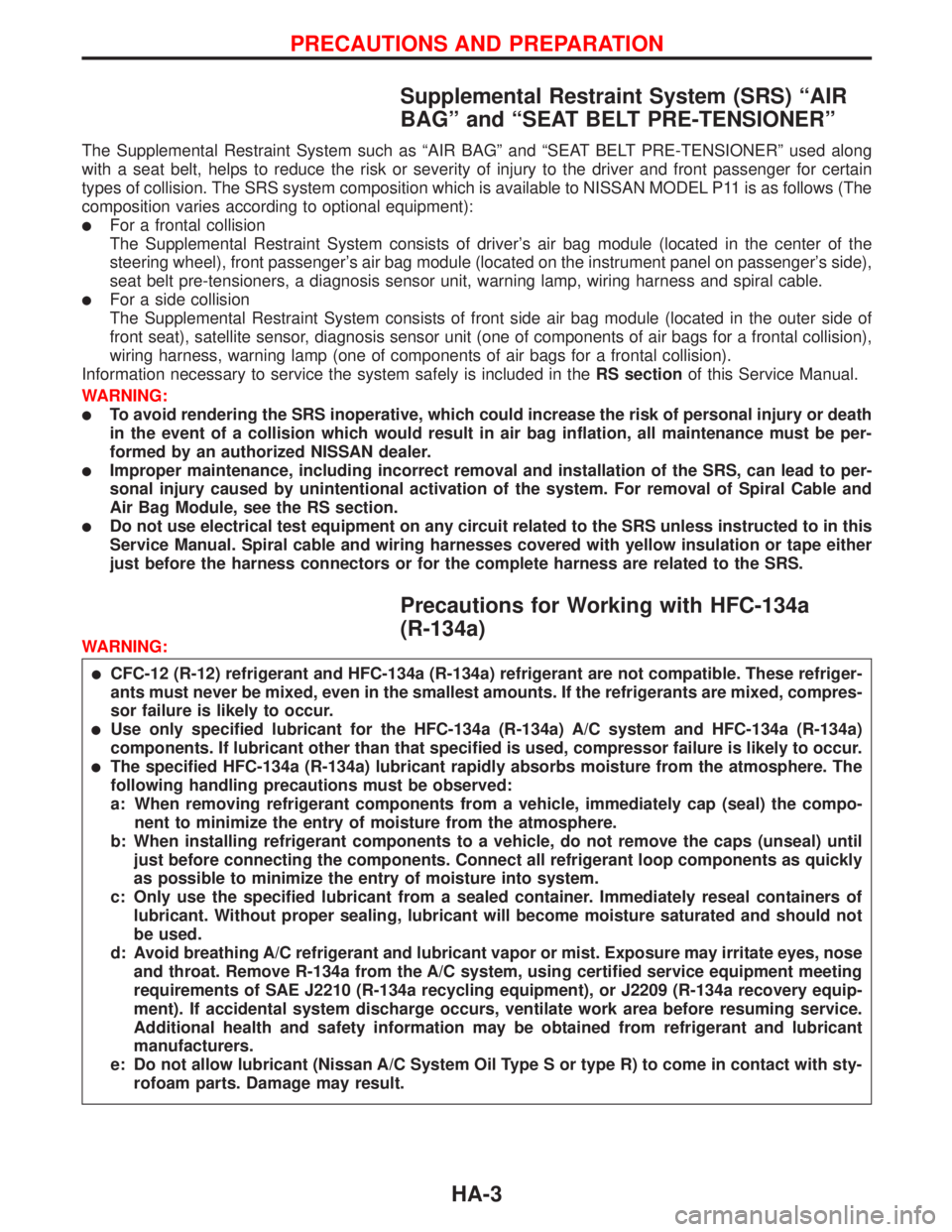
Supplemental Restraint System (SRS) ªAIR
BAGº and ªSEAT BELT PRE-TENSIONERº
The Supplemental Restraint System such as ªAIR BAGº and ªSEAT BELT PRE-TENSIONERº used along
with a seat belt, helps to reduce the risk or severity of injury to the driver and front passenger for certain
types of collision. The SRS system composition which is available to NISSAN MODEL P11 is as follows (The
composition varies according to optional equipment):
lFor a frontal collision
The Supplemental Restraint System consists of driver's air bag module (located in the center of the
steering wheel), front passenger's air bag module (located on the instrument panel on passenger's side),
seat belt pre-tensioners, a diagnosis sensor unit, warning lamp, wiring harness and spiral cable.
lFor a side collision
The Supplemental Restraint System consists of front side air bag module (located in the outer side of
front seat), satellite sensor, diagnosis sensor unit (one of components of air bags for a frontal collision),
wiring harness, warning lamp (one of components of air bags for a frontal collision).
Information necessary to service the system safely is included in theRS sectionof this Service Manual.
WARNING:
lTo avoid rendering the SRS inoperative, which could increase the risk of personal injury or death
in the event of a collision which would result in air bag inflation, all maintenance must be per-
formed by an authorized NISSAN dealer.
lImproper maintenance, including incorrect removal and installation of the SRS, can lead to per-
sonal injury caused by unintentional activation of the system. For removal of Spiral Cable and
Air Bag Module, see the RS section.
lDo not use electrical test equipment on any circuit related to the SRS unless instructed to in this
Service Manual. Spiral cable and wiring harnesses covered with yellow insulation or tape either
just before the harness connectors or for the complete harness are related to the SRS.
Precautions for Working with HFC-134a
(R-134a)
WARNING:
lCFC-12 (R-12) refrigerant and HFC-134a (R-134a) refrigerant are not compatible. These refriger-
ants must never be mixed, even in the smallest amounts. If the refrigerants are mixed, compres-
sor failure is likely to occur.
lUse only specified lubricant for the HFC-134a (R-134a) A/C system and HFC-134a (R-134a)
components. If lubricant other than that specified is used, compressor failure is likely to occur.
lThe specified HFC-134a (R-134a) lubricant rapidly absorbs moisture from the atmosphere. The
following handling precautions must be observed:
a: When removing refrigerant components from a vehicle, immediately cap (seal) the compo-
nent to minimize the entry of moisture from the atmosphere.
b: When installing refrigerant components to a vehicle, do not remove the caps (unseal) until
just before connecting the components. Connect all refrigerant loop components as quickly
as possible to minimize the entry of moisture into system.
c: Only use the specified lubricant from a sealed container. Immediately reseal containers of
lubricant. Without proper sealing, lubricant will become moisture saturated and should not
be used.
d: Avoid breathing A/C refrigerant and lubricant vapor or mist. Exposure may irritate eyes, nose
and throat. Remove R-134a from the A/C system, using certified service equipment meeting
requirements of SAE J2210 (R-134a recycling equipment), or J2209 (R-134a recovery equip-
ment). If accidental system discharge occurs, ventilate work area before resuming service.
Additional health and safety information may be obtained from refrigerant and lubricant
manufacturers.
e: Do not allow lubricant (Nissan A/C System Oil Type S or type R) to come in contact with sty-
rofoam parts. Damage may result.
PRECAUTIONS AND PREPARATION
HA-3
Page 1861 of 2267
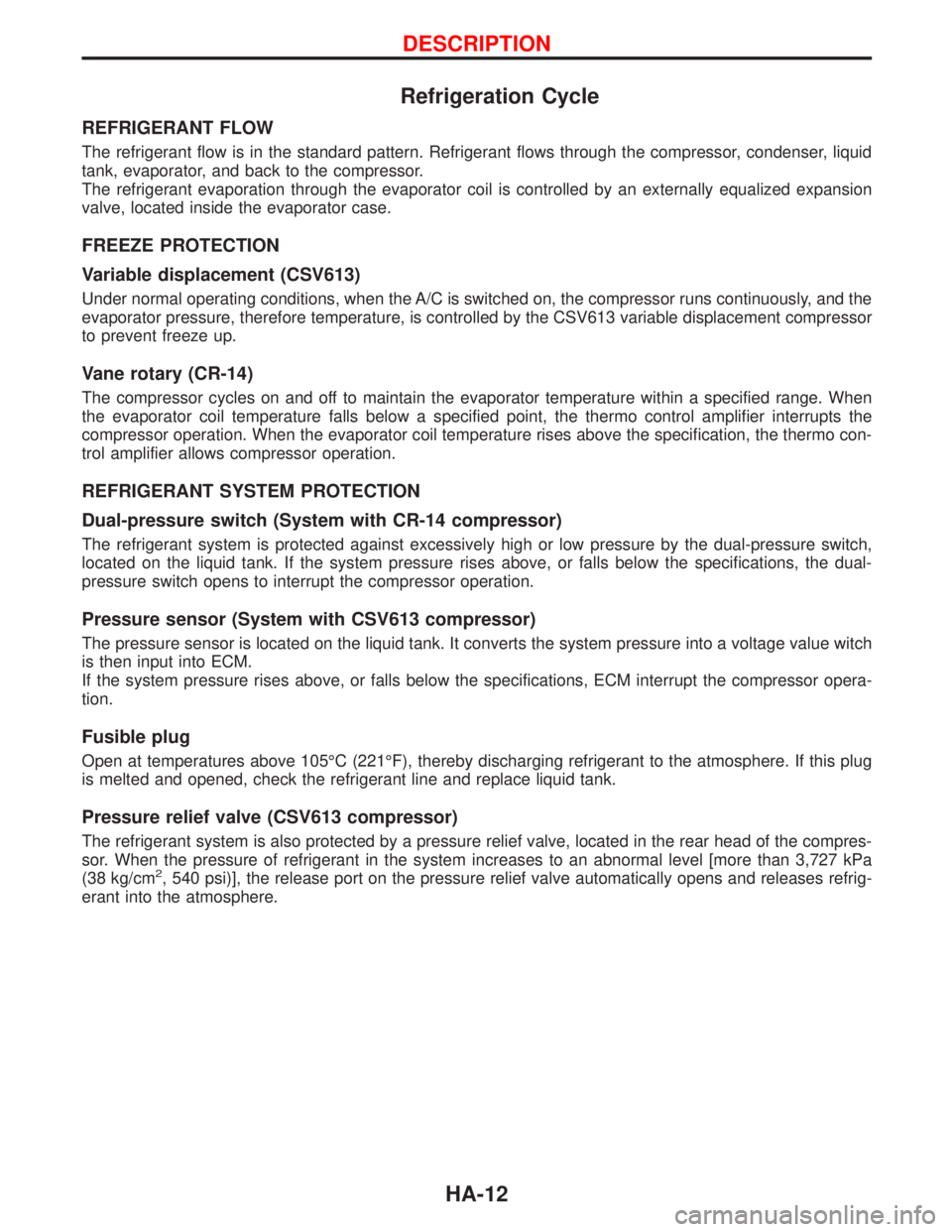
Refrigeration Cycle
REFRIGERANT FLOW
The refrigerant flow is in the standard pattern. Refrigerant flows through the compressor, condenser, liquid
tank, evaporator, and back to the compressor.
The refrigerant evaporation through the evaporator coil is controlled by an externally equalized expansion
valve, located inside the evaporator case.
FREEZE PROTECTION
Variable displacement (CSV613)
Under normal operating conditions, when the A/C is switched on, the compressor runs continuously, and the
evaporator pressure, therefore temperature, is controlled by the CSV613 variable displacement compressor
to prevent freeze up.
Vane rotary (CR-14)
The compressor cycles on and off to maintain the evaporator temperature within a specified range. When
the evaporator coil temperature falls below a specified point, the thermo control amplifier interrupts the
compressor operation. When the evaporator coil temperature rises above the specification, the thermo con-
trol amplifier allows compressor operation.
REFRIGERANT SYSTEM PROTECTION
Dual-pressure switch (System with CR-14 compressor)
The refrigerant system is protected against excessively high or low pressure by the dual-pressure switch,
located on the liquid tank. If the system pressure rises above, or falls below the specifications, the dual-
pressure switch opens to interrupt the compressor operation.
Pressure sensor (System with CSV613 compressor)
The pressure sensor is located on the liquid tank. It converts the system pressure into a voltage value witch
is then input into ECM.
If the system pressure rises above, or falls below the specifications, ECM interrupt the compressor opera-
tion.
Fusible plug
Open at temperatures above 105ÉC (221ÉF), thereby discharging refrigerant to the atmosphere. If this plug
is melted and opened, check the refrigerant line and replace liquid tank.
Pressure relief valve (CSV613 compressor)
The refrigerant system is also protected by a pressure relief valve, located in the rear head of the compres-
sor. When the pressure of refrigerant in the system increases to an abnormal level [more than 3,727 kPa
(38 kg/cm
2, 540 psi)], the release port on the pressure relief valve automatically opens and releases refrig-
erant into the atmosphere.
DESCRIPTION
HA-12