1999 NISSAN PRIMERA sensor
[x] Cancel search: sensorPage 1940 of 2267
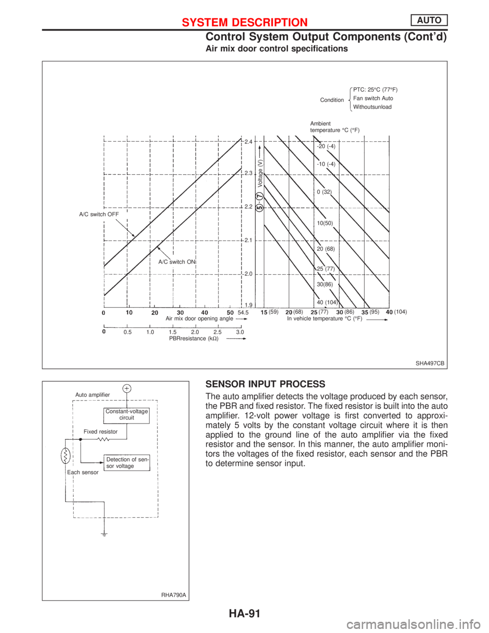
Air mix door control specifications
SENSOR INPUT PROCESS
The auto amplifier detects the voltage produced by each sensor,
the PBR and fixed resistor. The fixed resistor is built into the auto
amplifier. 12-volt power voltage is first converted to approxi-
mately 5 volts by the constant voltage circuit where it is then
applied to the ground line of the auto amplifier via the fixed
resistor and the sensor. In this manner, the auto amplifier moni-
tors the voltages of the fixed resistor, each sensor and the PBR
to determine sensor input.
SHA497CB A/C switch OFF
A/C switch ON
Voltage (V)
ConditionPTC: 25ÉC (77ÉF)
Fan switch Auto
Withoutsunload
Ambient
temperature ÉC (ÉF)
Air mix door opening angle In vehicle temperature ÉC (ÉF)
0.5 1.0 1.5 2.0 2.5 3.0
PBRresistance (kW)2.4
2.3
2.2
2.1
2.0
1.9
(59) (68) (77) (86) (95) (104)-20 (-4)
-10 (-4)
0 (32)
10(50)
20 (68)
25 (77)
30(86)
40 (104)
54.5
RHA790A Auto amplifier
Constant-voltage
circuit
Fixed resistor
Detection of sen-
sor voltage
Each sensor
SYSTEM DESCRIPTIONAUTO
Control System Output Components (Cont'd)
HA-91
Page 1944 of 2267
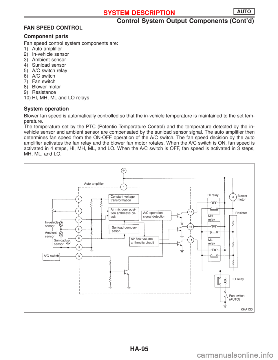
FAN SPEED CONTROL
Component parts
Fan speed control system components are:
1) Auto amplifier
2) In-vehicle sensor
3) Ambient sensor
4) Sunload sensor
5) A/C switch relay
6) A/C switch
7) Fan switch
8) Blower motor
9) Resistance
10) HI, MH, ML and LO relays
System operation
Blower fan speed is automatically controlled so that the in-vehicle temperature is maintained to the set tem-
perature.
The temperature set by the PTC (Potentio Temperature Control) and the temperature detected by the in-
vehicle sensor and ambient sensor are compensated by the sunload sensor signal. The auto amplifier then
determines fan speed from the ON-OFF operation of the A/C switch. The fan speed decision by the auto
amplifier activates the fan relay and the blower fan motor rotates. When the A/C switch is ON, fan speed is
activated in 4 steps, HI, MH, ML, and LO. When the A/C switch is OFF, fan speed is activated in 3 steps,
MH, ML, and LO.
KHA130 Auto amplifier
In-vehicle
sensor
Ambient
sensor
Sunload
sensor
A/C switchConstant voltage
transformation
Air mix door posi-
tion arithmetic cir-
cuit
Sunload compen-
sationA/C operation
signal detection
Air flow volume
arithmetic circuitHI relay
MH
relay
ML
relayBlower
motor
Resistor
LO relay
Fan switch
(AUTO)
SYSTEM DESCRIPTIONAUTO
Control System Output Components (Cont'd)
HA-95
Page 1945 of 2267
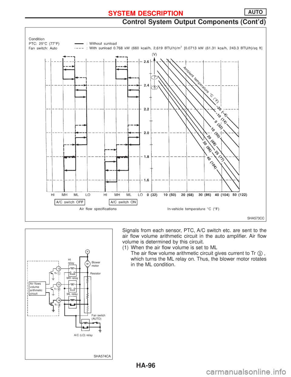
Signals from each sensor, PTC, A/C switch etc. are sent to the
air flow volume arithmetic circuit in the auto amplifier. Air flow
volume is determined by this circuit.
(1) When the air flow volume is set to ML
The air flow volume arithmetic circuit gives current to Tr
p3,
which turns the ML relay on. Thus, the blower motor rotates
in the ML condition.
SHA573CC
SHA574CA
Air flows
volume
arithmetic
circuitHI
relay
MH relay
ML relayBlower
motor
Resistor
Fan switch
(AUTO)
A/C (LO) relay
SYSTEM DESCRIPTIONAUTO
Control System Output Components (Cont'd)
HA-96
Page 1947 of 2267
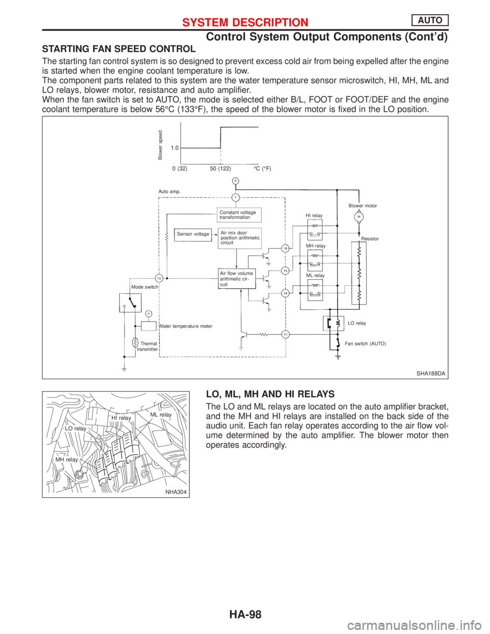
STARTING FAN SPEED CONTROL
The starting fan control system is so designed to prevent excess cold air from being expelled after the engine
is started when the engine coolant temperature is low.
The component parts related to this system are the water temperature sensor microswitch, HI, MH, ML and
LO relays, blower motor, resistance and auto amplifier.
When the fan switch is set to AUTO, the mode is selected either B/L, FOOT or FOOT/DEF and the engine
coolant temperature is below 56ÉC (133ÉF), the speed of the blower motor is fixed in the LO position.
LO, ML, MH AND HI RELAYS
The LO and ML relays are located on the auto amplifier bracket,
and the MH and HI relays are installed on the back side of the
audio unit. Each fan relay operates according to the air flow vol-
ume determined by the auto amplifier. The blower motor then
operates accordingly.
SHA188DA
Blower speed
1.0
0 (32) 50 (122) ÉC (ÉF)
Auto amp.
.Constant voltage
transformation
Sensor voltage
.Air mix door
position arithmetic
circuit
Air flow volume
arithmetic cir-
cuit
Mode switch
Water temperature meter
Thermal
transmitterFan switch (AUTO)LO relay ML relay MH relay HI relay
.Blower motor
Resistor
NHA304
.LO relay
.ML relay.HI relay
.MH relay
SYSTEM DESCRIPTIONAUTO
Control System Output Components (Cont'd)
HA-98
Page 1955 of 2267
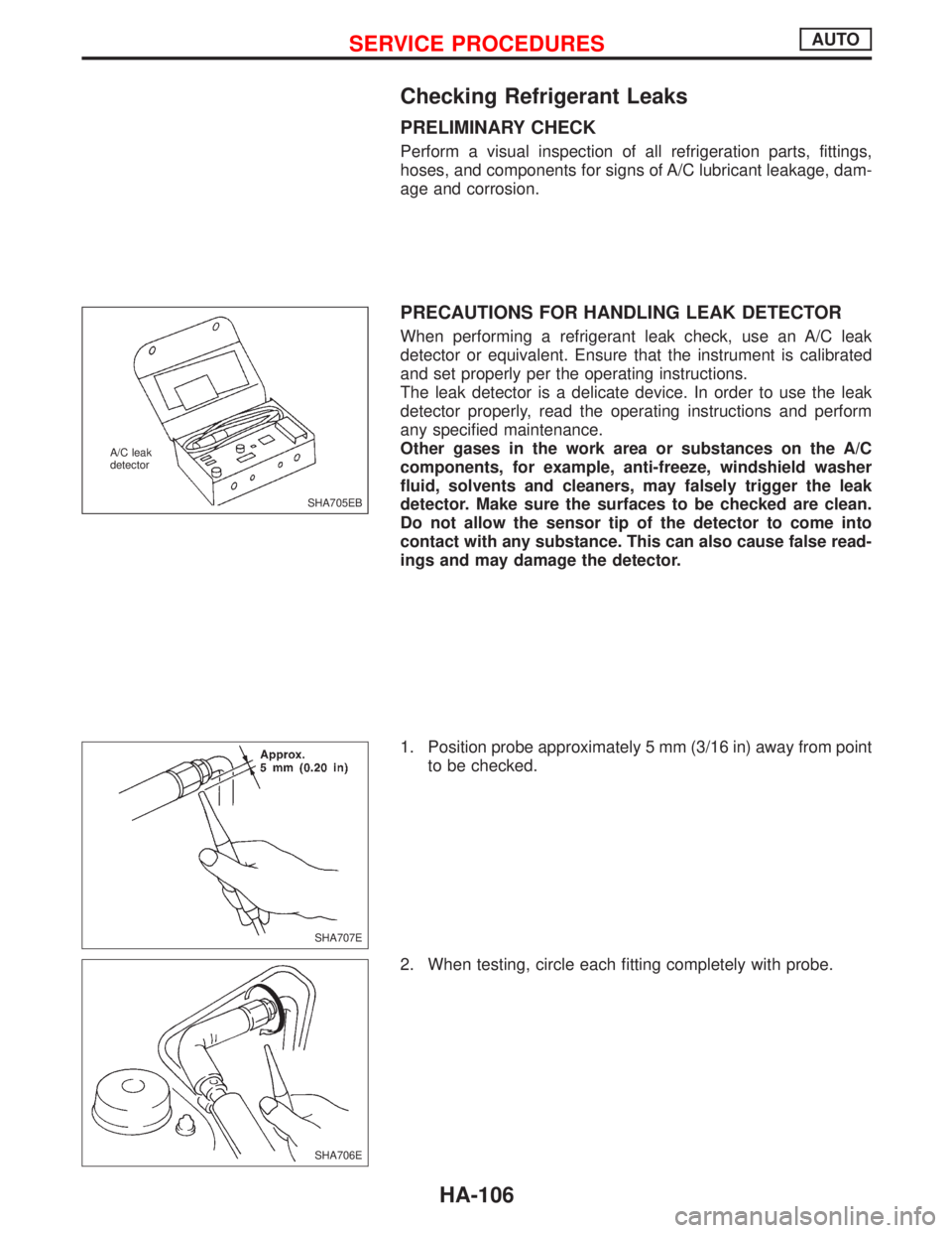
Checking Refrigerant Leaks
PRELIMINARY CHECK
Perform a visual inspection of all refrigeration parts, fittings,
hoses, and components for signs of A/C lubricant leakage, dam-
age and corrosion.
PRECAUTIONS FOR HANDLING LEAK DETECTOR
When performing a refrigerant leak check, use an A/C leak
detector or equivalent. Ensure that the instrument is calibrated
and set properly per the operating instructions.
The leak detector is a delicate device. In order to use the leak
detector properly, read the operating instructions and perform
any specified maintenance.
Other gases in the work area or substances on the A/C
components, for example, anti-freeze, windshield washer
fluid, solvents and cleaners, may falsely trigger the leak
detector. Make sure the surfaces to be checked are clean.
Do not allow the sensor tip of the detector to come into
contact with any substance. This can also cause false read-
ings and may damage the detector.
1. Position probe approximately 5 mm (3/16 in) away from point
to be checked.
2. When testing, circle each fitting completely with probe.
SHA705EB A/C leak
detector
SHA707E
SHA706E
SERVICE PROCEDURESAUTO
HA-106
Page 1969 of 2267
A
AAC/V - Wiring diagram....EC-QG-276, EC-SR-265
ABS (anti-lock brake system).........................BR-50
A/C control linkage adjustment (manual
A/C) .............................................................HA-82
A/C control operation (auto A/C) ....................HA-19
A/C diagnostic work flow (auto A/C) ..............HA-26
A/C performance chart ...................................HA-35
A/C performance test diagnoses....................HA-33
A/C relay.........................................................HA-78
A/C service data specification ......................HA-118
A/C switch ......................................................HA-78
A/C symptom chart (auto A/C) .......................HA-28
A/C trouble diagnoses (auto A/C) ..................HA-26
Accelerator control system ...............................FE-3
Accelerator position sensor ...................EC-CD-108
Accelerator position switch ....................EC-CD-108
Accelerator wire adjustment .............................FE-4
A/CCUT - Wiring diagram ......................EC-CD-127
Air bag disposal..............................................RS-27
Air bag precautions ...........................................GI-3
Air bleeding for brake system ..........................BR-8
Air cleaner filter replacement ............MA-23, 34, 44
Air conditioner cut
control .....EC-QG-24, EC-SR-26, EC-CD-20, 126
Air flow meter - See Mass air flow
sensor ............................EC-QG-110, EC-SR-120
Air mix. door motor.........................................HA-92
Alternator ..................................................EL-53, 56
Ambient sensor ..............................................HA-86
Antenna .........................................................EL-229
Anti-lock brake system - See ABS .................BR-50
APS - Wiring diagram ............................EC-CD-109
A/T - Wiring diagram - AT - FTS .....................AT-56
A/T - Wiring diagram - AT - MAIN ...................AT-45
A/T - Wiring diagram - AT - PNP/SW..............AT-50
A/T - Wiring diagram - AT - VSS A/T ..............AT-64
A/T diagnosis communication line .........EC-SR-295
A/T fluid temperature sensor...........................AT-54
A/T trouble diagnoses ...............................AT-29, 30
A/T Wiring diagram - AT - ENG SS ................AT-67
A/T Wiring diagram AT - LPSV .......................AT-76
A/T Wiring diagram AT - TCV .........................AT-71
A/T Wiring diagram AT - TPS..........................AT-81
ATDIAG - Wiring diagram ......................EC-SR-296
Audio .............................................................EL-216
AUDIO - Wiring diagram ...............................EL-219
Audio and A/C control removal and
installation - See Instrument panel .............BT-15
Auto air conditioner - Wiring diagram ............HA-42
Automatic amplifier .........................................HA-87
Automatic transaxle number............................GI-44
Automatic transmission fluid
replacement..........................................MA-49, 50
Auxiliary air control (AAC)
valve ..............................EC-QG-274, EC-SR-263BBack door opener - See Back door ............BT-9, 11
Back door trim.................................................BT-30
Back door window ....................................BT-35, 56
Back-up lamp ................................................EL-107
BACK/L - Wiring diagram..............................EL-107
Ball joint front axle ....................................FA-32, 33
Base idle air volume
initialiging ...........................EC-QG-33, EC-SR-46
Basic inspection ....................EC-QG-72, EC-SR-84
Battery .............................................................EL-29
Body alignment ...............................................BT-60
Brake booster .................................................BR-18
Brake control valve (Proportioning
valve)...........................................................BR-11
Brake fluid change ...........................................BR-7
Brake fluid level .............................................MA-51
Brake fluid level and line check .......................BR-7
Brake hydraulic line ..........................................BR-9
Brake inspection ............................................MA-51
Brake lining wear temporary checking ..........MA-51
Brake pedal ....................................................BR-13
Bulb specifications ........................................EL-137
Bumper, front ....................................................BT-5
Bumper, rear .......................................BT-5, 7, 9, 11
BUZZER - Wiring diagram ............................EL-181
C
Camshaft inspection ...............EM-35, 91, 138, 147,
183, 192, 196
Camshaft position sensor
(CMPS) ..........................EC-QG-238, EC-SR-239
Camshaft position sensor (PHASE) ......EC-QG-238
Canister-See EVAP
canister ..............................EC-QG-25, EC-SR-27
CHARGE - Wiring diagram .............................EL-53
Charging system .............................................EL-53
Chassis and body maintenance ....................MA-48
CHIME - Wiring diagram ...............................EL-181
Cigarette lighter.............................................EL-203
Circuit breaker.................................................EL-22
CKPS - Wiring diagram....EC-QG-234, EC-SR-236,
292, EC-CD-115
Clock .............................................................EL-203
Closed throttle position switch ...............EC-SR-271
Clutch cover ....................................................CL-13
Clutch damper ................................................CL-10
Clutch disc ......................................................CL-13
Clutch fluid level.............................................MA-48
Clutch master cylinder ......................................CL-8
Clutch operating cylinder ..................................CL-9
Clutch release mechanism..............................CL-11
CMPS - Wiring diagram ....EC-QG-240, EC-SR-242
Coil spring (rear) .............................................RA-11
Collision diagnosis..........................................RS-57
Combination meter........................................EL-138
ALPHABETICAL INDEX
IDX-2
Page 1970 of 2267
Combination meter removal and instal-
lation - See Instrument panel ......................BT-15
Combination switch .........................................EL-64
Combustion chamber replacement ..............EM-146
Component location (cool box) ......................HA-39
Compression pressure ..........EM-69, 126, 188, 196
Compressor clutch removal and
installation .................................................HA-111
Compressor mounting ..................................HA-109
Compressor precaution ....................................HA-7
Compressor special service tool ......................HA-7
Connecting rod......EM-55, 171, 176, 186, 193, 200
Connecting rod bearing
clearance....EM-58, 111, 115, 170, 187, 195, 201
Connecting rod bushing clearance ........EM-59, 116
Console box - See Instrument panel ..............BT-15
CONSULT for ABS .........................................BR-69
CONSULT for engine ...........EC-QG-55, EC-SR-68,
EC-CD-27
CONSULT-II general information .....................GI-39
Control sleeve position sensor ................EC-CD-74
Converter housing installation .......................AT-117
COOL/F - Wiring diagram ....................EC-QG-292,
EC-SR-282, EC-CD-89
Coolant replacement .........................MA-19, 29, 40
Cooling circuit (engine) ........................LC-8, 21, 31
Cooling fan control ...........EC-QG-289, EC-SR-279,
EC-CD-20, 87
Cooling fan motor .............EC-QG-299, EC-SR-289
Cooling fan relay ..............EC-QG-299, EC-SR-289,
EC-CD-96
Crank angle sensor built into distributor
- See Camshaft position sensor .......EC-QG-238,
EC-SR-239
‘‘Crankcase emission control system -
See positive crankcase
ventilation’’ .........................EC-QG-28, EC-SR-30
Crankcase ventilation system - See
Positive crankcase
ventilation ..........................EC-QG-28, EC-SR-30
Crankshaft ........EM-53, 57, 61, 110, 113, 118, 131,
138, 139, 167, 172, 175, 186, 194, 200
Crankshaft position sensor (OBD) .......EC-QG-232,
EC-SR-234, 290
Crankshaft position sensor (POS).........EC-QG-232
Crankshaft position sensor (TDC)..........EC-CD-114
CSPS - Wiring diagram ...........................EC-CD-75
Cylinder block .........................EM-52, 55, 109, 166,
173, 184, 192, 199
Cylinder head ..........EM-31, 86, 140, 178, 188, 196
D
Data link connector for
Consult ..............................EC-QG-29, EC-SR-31
Daytime light system.......................................EL-78
DEF - Wiring diagram ...................................EL-209
Detonation sensor - See Knock
sensor ............................EC-QG-228, EC-SR-230
Diagnosis sensor unit .....................................RS-13Diagnostic trouble code (DTC) for OBD
system ...................................EC-QG-6, EC-SR-6
Diagnostic trouble code (DTC) inspec-
tion priority chart...............EC-QG-80, EC-SR-92,
EC-CD-39
Dimensions ......................................................GI-45
Direct ignition system ..............................EC-QG-32
Door lock .........................................................BT-13
Door mirror ......................................................BT-58
Door trim .........................................................BT-24
Door, front .......................................................BT-13
Door, rear ........................................................BT-13
Drive belt inspection ..........................MA-18, 28, 39
Drive plate runout...................................EM-60, 117
Drive shaft (front) ............................................FA-15
Dropping resistor (A/T) ....................................AT-78
DTC work support .................EC-QG-63, EC-SR-76
DTRL - Wiring diagram ...................................EL-79
E
ECCS relay ............................................EC-CD-140
ECM input/output signal......EC-QG-91, EC-SR-103
ECTS - Wiring diagram ....EC-QG-122, EC-SR-134,
EC-CD-67
EGR control (EGRC) - solenoid valve ...EC-CD-129
EGR control valve..........................EC-QG-252, 311
EGR temperature sensor ......................EC-QG-300
EGR/TS - Wiring diagram .....................EC-QG-302
EGRC - Wiring diagram .........................EC-CD-131
EGRC1 - Wiring diagram ..............EC-QG-248, 309
Electric governer ......................................EC-CD-78
Electric sun roof ............................................EL-230
Electrical diagnoses.........................................GI-24
Electrical ignition system.......EC-QG-23, EC-SR-25
Electrical unit ................................................Foldout
Electronic fuel injection pump ..................EC-CD-24
Engine control circuit
diagram ...........EC-QG-17, EC-SR-19, EC-CD-11
Engine control component parts
location ..............................EC-QG-14, EC-SR-15
Engine control module
(ECM) .....EC-QG-282, EC-SR-277, EC-CD-9, 86
Engine control system diagram and
chart ................EC-QG-18, EC-SR-20, EC-CD-12
Engine coolant temperature sensor
(ECTS) ........EC-QG-120, EC-SR-132, EC-CD-66
Engine fail-safe system .........EC-QG-81, EC-SR-93
Engine oil filter replacement ....................MA-24, 45
Engine oil precautions .......................................GI-6
Engine oil replacement ......................MA-24, 34, 45
Engine removal..............................EM-48, 106, 162
Engine serial number ......................................GI-44
Engine trouble diagnoses ........................EC-CD-33
EVAP canister .......................EC-QG-26, EC-SR-28
EVAP canister purge volume control
solenoid valve ...........EC-QG-26, 262, EC-SR-28
EVAP canister purge volume control
valve ..............................EC-QG-262, EC-SR-250
EVAP vapor lines inspection....................MA-26, 37
ALPHABETICAL INDEX
IDX-3
Page 1971 of 2267
Evaporative emission (EVAP)
system ...............................EC-QG-25, EC-SR-27
Exhaust gas recirculation (EGR)
valve...........................................EC-QG-244, 305
Exhaust system ................................................FE-9
Exhaust system inspection ............................MA-48
Exterior ............................................................BT-31
F
FCUT - Wiring diagram ..........................EC-CD-101
F/FOG - Wiring diagram................................EL-110
Final drive (FF M/T) ...........................MT-32, 51, 71
Floor trim .........................................................BT-18
Fluid temperature sensor (A/T) .......................AT-94
Fluids..............................................................MA-16
Flywheel (clutch) .............................................CL-14
Flywheel runout..............................EM-60, 117, 177
Fog lamp, front ..............................................EL-110
Fog lamp, rear ...............................................EL-112
F/PUMP - Wiring
diagram..........................EC-QG-338, EC-SR-317
Freeze frame data ................EC-QG-38, EC-SR-50
Fresh vent door control linkage
adjustment ..................................................HA-83
FRO2 - Wiring diagram ........EC-QG-135, 154, 162,
EC-SR-147, 165, 172
FRO2/H - Wiring
diagram..........................EC-QG-168, EC-SR-177
Front axle ..........................................................FA-9
Front bumper ....................................................BT-5
Front disc brake .............................................BR-23
Front door .......................................................BT-13
Front fog lamp .......................................EL-110, 111
Front fog lamp removal and installation ...........BT-5
Front heated oxygen sensor
(HO2S) ......................................EC-QG-132, 139,
EC-SR-144, 150, 156, 162, 170
Front heated oxygen sensor (HO2S)
heater ............................EC-QG-166, EC-SR-175
Front passenger air bag .................................RS-17
Front seat ........................................................BT-40
Front seat belt ..................................................RS-3
Front suspension ............................................FA-26
Front washer .................................................EL-186
Front wiper ....................................................EL-186
FTS - Wiring diagram ............................EC-CD-105
FUEL - Wiring
diagram .........EC-QG-210, 217, EC-SR-213, 220
Fuel cut control (at no load & high
engine speed)....................EC-QG-25, EC-SR-27
Fuel cut solenoid valve ..........................EC-CD-100
Fuel filter ...............................EC-QG-29, EC-SR-31
Fuel filter replacement .......................MA-23, 33, 43
Fuel gauge ............................................EL-141, 146
Fuel injection system....................EC-QG-208, 215,
EC-SR-212, 218,
EC-CD-15, 18
Fuel injector ......................EC-QG-318, EC-SR-302
Fuel line inspection............................MA-22, 33, 43Fuel precautions ................................................GI-7
Fuel pressure check .............EC-QG-29, EC-SR-31
Fuel pressure regulator .........EC-QG-30, EC-SR-32
Fuel pressure release ...........EC-QG-29, EC-SR-31
Fuel pump .........................EC-QG-336, EC-SR-316
Fuel pump and gauge ......................................FE-7
Fuel pump relay ................EC-QG-336, EC-SR-316
Fuel system ......................................................FE-6
Fuel tank vacuum relief
valve ..................................EC-QG-26, EC-SR-28
Fuel temperature sensor .................EC-CD-17, 104
Fuse ..................................................EL-22, Foldout
Fuse block ....................................................Foldout
Fusible link ........................................EL-22, Foldout
G
Garage jack and safety stand .........................GI-47
Gauges..........................................................EL-138
Gear components (M/T) ...........................MT-16, 49
Generic scan tool (GST) .......EC-QG-66, EC-SR-78
GLOW - Wiring diagram ........................EC-CD-120
Glow plug .........................................EC-CD-15, 118
Glow relay ................................................EC-CD-15
GOVNR - Wiring diagram ........................EC-CD-79
Grille - See Exterior ........................................BT-38
Ground distribution..........................................EL-23
H
H/AIM - Wiring diagram ....................EL-87, 93, 200
Harness connector ............................................EL-6
Harness layout ..............................................EL-368
Hazard warning lamp ....................................EL-117
Headlamp..................................................EL-67, 69
Headlamp aiming control ................................EL-87
Headlamp washer .........................................EL-200
Headlining - See Roof trim .............................BT-25
Heated oxygen sensor (HO2S)
(front) ........................................EC-QG-132, 139,
EC-SR-144, 150, 156, 162, 170
Heated oxygen sensor (HO2S) heater
(front) .............................EC-QG-166, EC-SR-175
Heated oxygen sensor (HO2S) heater
(rear) ..............................EC-QG-203, EC-SR-207
Heated oxygen sensor (rear) ...............EC-QG-171,
EC-SR-180, 187,
194, 201
Heated oxygen sensor inspection ...........MA-27, 38
Heated seat .......................................BT-42, EL-234
HEATER - Wiring diagram .............................HA-40
HFC134a (R134a) system service
procedure ..................................................HA-100
HFC134a (R134a) system service tools ..........HA-8
H/LAMP - Wiring diagram ...............................EL-67
Hood..................................................................BT-5
Horn ..............................................................EL-203
HORN - Wiring diagram ................................EL-203
ALPHABETICAL INDEX
IDX-4