Page 2032 of 2267

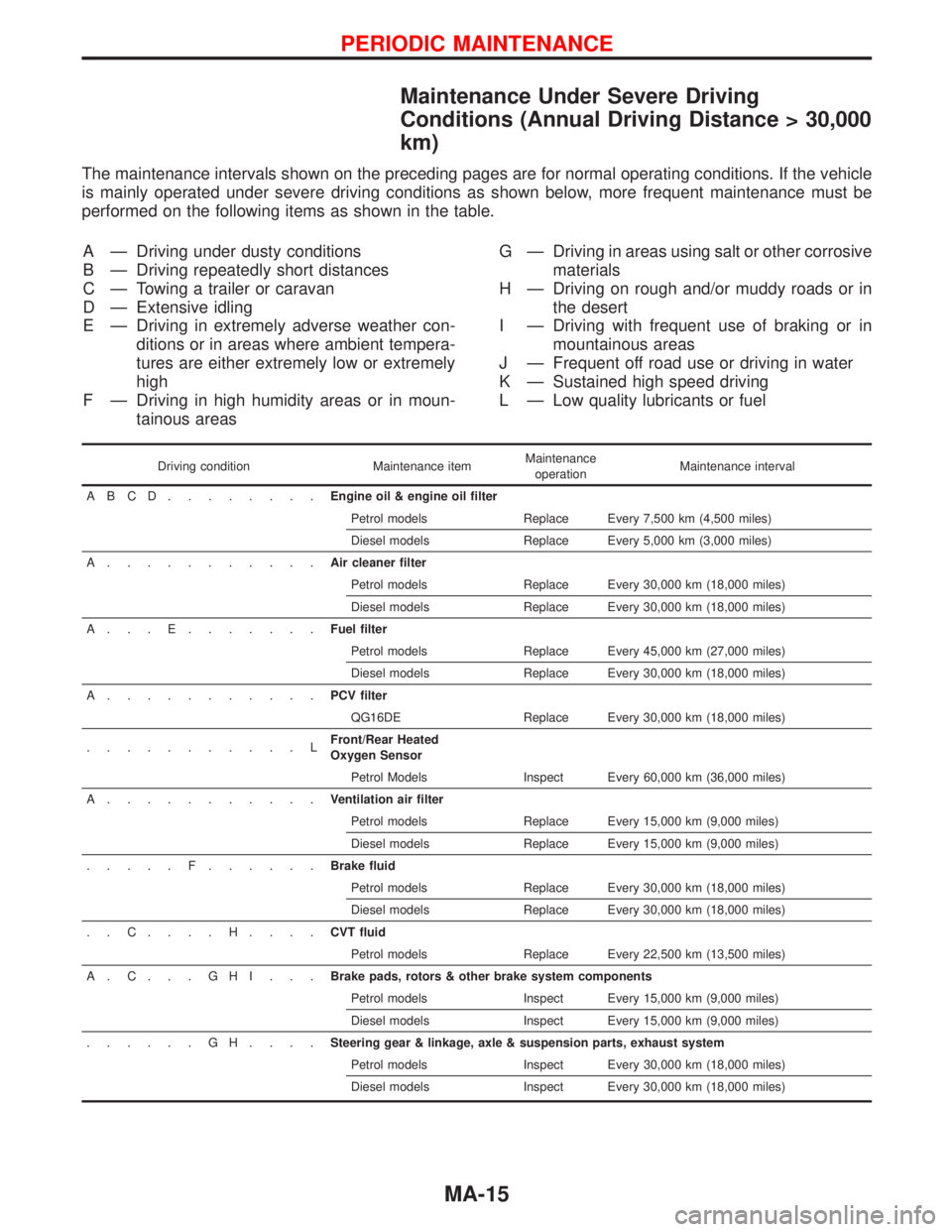
Maintenance Under Severe Driving
Conditions (Annual Driving Distance > 30,000
km)
The maintenance intervals shown on the preceding pages are for normal operating conditions. If the vehicle
is mainly operated under severe driving conditions as shown below, more frequent maintenance must be
performed on the following items as shown in the table.
A—Driving under dusty conditions
B—Driving repeatedly short distances
C—Towing a trailer or caravan
D—Extensive idling
E—Driving in extremely adverse weather con-
ditions or in areas where ambient tempera-
tures are either extremely low or extremely
high
F—Driving in high humidity areas or in moun-
tainous areasG—Driving in areas using salt or other corrosive
materials
H—Driving on rough and/or muddy roads or in
the desert
I—Driving with frequent use of braking or in
mountainous areas
J—Frequent off road use or driving in water
K—Sustained high speed driving
L—Low quality lubricants or fuel
Driving condition Maintenance itemMaintenance
operationMaintenance interval
ABCD........Engine oil & engine oil filter
Petrol models Replace Every 7,500 km (4,500 miles)
Diesel models Replace Every 5,000 km (3,000 miles)
A...........Air cleaner filter
Petrol models Replace Every 30,000 km (18,000 miles)
Diesel models Replace Every 30,000 km (18,000 miles)
A...E.......Fuel filter
Petrol models Replace Every 45,000 km (27,000 miles)
Diesel models Replace Every 30,000 km (18,000 miles)
A...........PCV filter
QG16DE Replace Every 30,000 km (18,000 miles)
...........LFront/Rear Heated
Oxygen Sensor
Petrol Models Inspect Every 60,000 km (36,000 miles)
A...........Ventilation air filter
Petrol models Replace Every 15,000 km (9,000 miles)
Diesel models Replace Every 15,000 km (9,000 miles)
.....F......Brake fluid
Petrol models Replace Every 30,000 km (18,000 miles)
Diesel models Replace Every 30,000 km (18,000 miles)
..C....H....CVT fluid
Petrol models Replace Every 22,500 km (13,500 miles)
A.C...GHI...Brake pads, rotors & other brake system components
Petrol models Inspect Every 15,000 km (9,000 miles)
Diesel models Inspect Every 15,000 km (9,000 miles)
......GH....Steering gear & linkage, axle & suspension parts, exhaust system
Petrol models Inspect Every 30,000 km (18,000 miles)
Diesel models Inspect Every 30,000 km (18,000 miles)
PERIODIC MAINTENANCE
MA-15
Page 2044 of 2267
Checking Front Heated Oxygen Sensor
(HO2S)
Checking procedure
INSPECTION START
Start engine and warm it up until water temperature indicator points to the
middle of gauge.
1. See“M/R F/C MNT”in“Data monitor”mode.
2. Run engine at about 2,000 rpm for about 2 minutes under no-
load.
3. Maintaining engine at 2,000 rpm under no-load (engine is
warmed up sufficiently.), check that the monitor fluctuates
between“LEAN”and“RICH”more than 5 times during 10 sec-
onds.
1 time RICH→LEAN→RICH
2 times RICH→LEAN→RICH→LEAN→RICH ...
OK NG
INSPECTION END
Check and adjustment should be made by
referring to IDLE SPEED/IGNITION TIMING/
IDLE MIXTURE RATIO INSPECTION (BASIC
SERVICE PROCEDURE) in EC section.
C2DMM06
NEF125A Data link connector.NEF125A Fuse box
SEF051PA Malfunction indicator lamp
�
�
��
ENGINE MAINTENANCEQG
MA-27
Page 2055 of 2267
Checking Front Heated Oxygen Sensor
(HO2S)
Checking procedure
INSPECTION START
Start engine and warm up until water temperature indicator points to the
middle of gauge.
1. See“M/R F/C MNT”in“Data monitor”mode.
2. Run engine at about 2,000 rpm for about 2 minutes under no-
load.
3. Maintaining engine at 2,000 rpm under no-load (engine is
warmed up sufficiently.), check that the monitor fluctuates
between“LEAN”and“RICH”more than 5 times during 10 sec-
onds.
1 time RICH→LEAN→RICH
2 times RICH→LEAN→RICH→LEAN→RICH ...
OK NG
INSPECTION END
Check and adjustment should be made by
referring to IDLE SPEED/IGNITION TIMING/
IDLE MIXTURE RATIO INSPECTION (BASIC
SERVICE PROCEDURE) in EC section.
PEF054P
NEF125A Data link connector.NEF125A Fuse box
SEF051PA Malfunction indicator lamp
�
�
��
ENGINE MAINTENANCESR20DE
MA-38
Page 2060 of 2267
Pull the negative-pressure valve to open it. Check that it closes
completely when released.
CHECKING COOLING SYSTEM FOR LEAKS
Apply pressure to the cooling system with cap tester to check for
leakage.
Testing pressure:
157 kPa (1.57 bar, 1.6 kg/cm
2, 23 psi)
CAUTION:
Higher pressure than the specified value may cause damage
to radiator.
Checking Fuel Lines
Inspect fuel lines and tank for improper attachment and for leaks,
cracks, damage, loose connections, chafing and deterioration.
If necessary, repair or replace faulty parts.
Checking and Replacing Fuel Filter and
Draining Water
CHECKING FUEL FILTER
Check fuel filter for fuel leakage, damage and other abnormal
signs.
REPLACING FUEL FILTER
1. Disconnect fuel filter sensor connector and drain fuel.
SMA871B
SMA990A Hose adapter
EG17650301
SMA803A
Engine
Fuel line
Fuel tank
SMA794C Loosen
Drain valve
ENGINE MAINTENANCECD20T
Checking Cooling System (Cont’d)
MA-43
Page 2061 of 2267

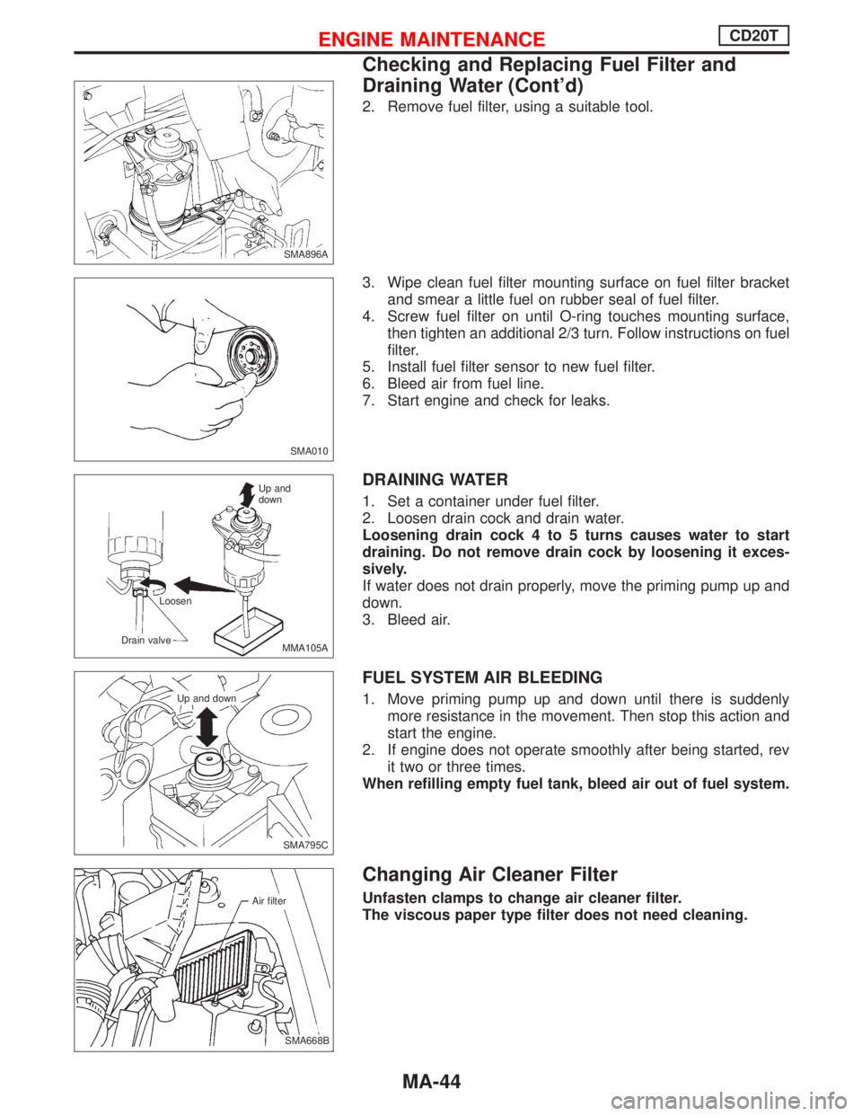
2. Remove fuel filter, using a suitable tool.
3. Wipe clean fuel filter mounting surface on fuel filter bracket
and smear a little fuel on rubber seal of fuel filter.
4. Screw fuel filter on until O-ring touches mounting surface,
then tighten an additional 2/3 turn. Follow instructions on fuel
filter.
5. Install fuel filter sensor to new fuel filter.
6. Bleed air from fuel line.
7. Start engine and check for leaks.
DRAINING WATER
1. Set a container under fuel filter.
2. Loosen drain cock and drain water.
Loosening drain cock 4 to 5 turns causes water to start
draining. Do not remove drain cock by loosening it exces-
sively.
If water does not drain properly, move the priming pump up and
down.
3. Bleed air.
FUEL SYSTEM AIR BLEEDING
1. Move priming pump up and down until there is suddenly
more resistance in the movement. Then stop this action and
start the engine.
2. If engine does not operate smoothly after being started, rev
it two or three times.
When refilling empty fuel tank, bleed air out of fuel system.
Changing Air Cleaner Filter
Unfasten clamps to change air cleaner filter.
The viscous paper type filter does not need cleaning.
SMA896A
SMA010
MMA105A Loosen
Drain valveUp and
down
SMA795C Up and down
.SMA668B Air filter
ENGINE MAINTENANCECD20T
Checking and Replacing Fuel Filter and
Draining Water (Cont’d)
MA-44
Page 2063 of 2267

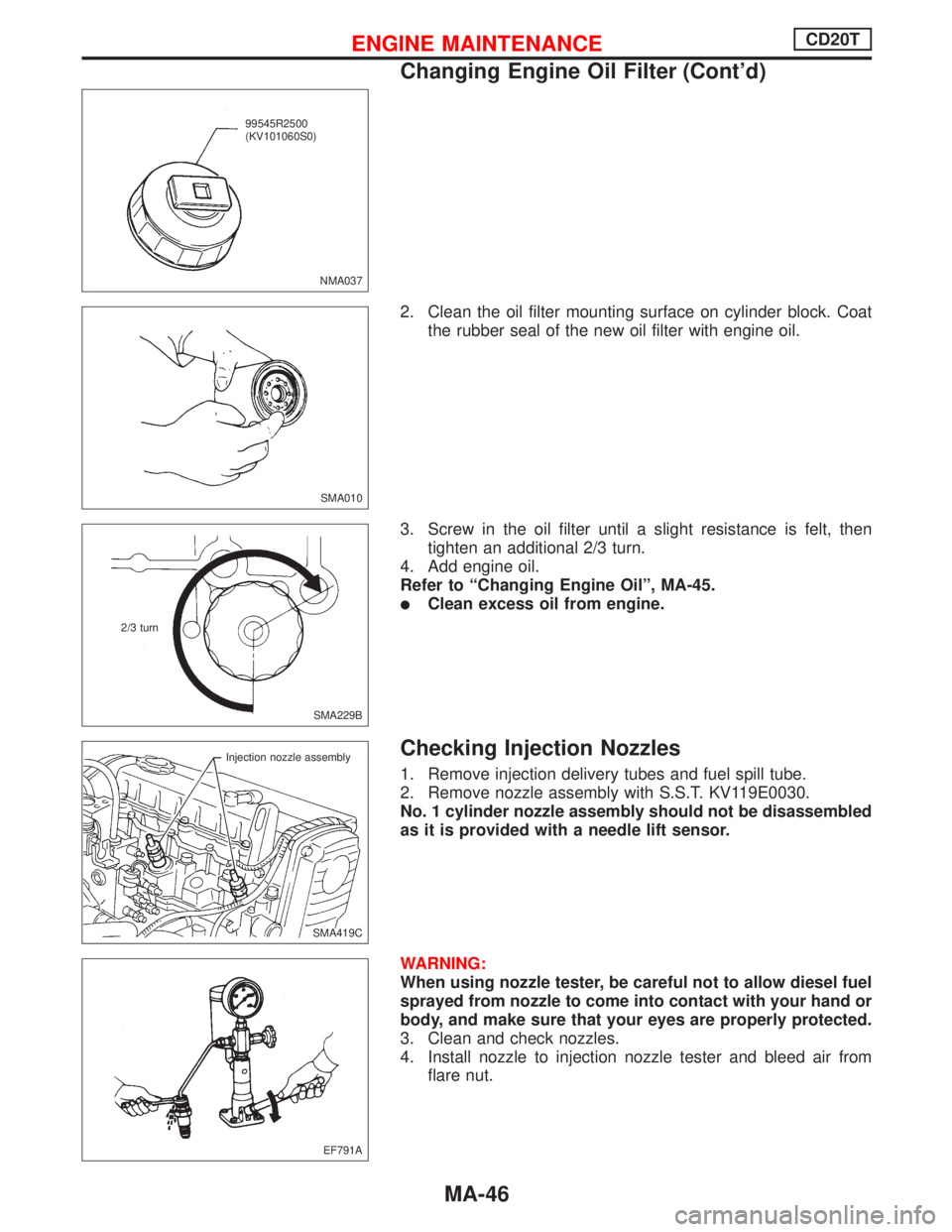
2. Clean the oil filter mounting surface on cylinder block. Coat
the rubber seal of the new oil filter with engine oil.
3. Screw in the oil filter until a slight resistance is felt, then
tighten an additional 2/3 turn.
4. Add engine oil.
Refer to“Changing Engine Oil”, MA-45.
�Clean excess oil from engine.
Checking Injection Nozzles
1. Remove injection delivery tubes and fuel spill tube.
2. Remove nozzle assembly with S.S.T. KV119E0030.
No. 1 cylinder nozzle assembly should not be disassembled
as it is provided with a needle lift sensor.
WARNING:
When using nozzle tester, be careful not to allow diesel fuel
sprayed from nozzle to come into contact with your hand or
body, and make sure that your eyes are properly protected.
3. Clean and check nozzles.
4. Install nozzle to injection nozzle tester and bleed air from
flare nut.
NMA037
.99545R2500
(KV101060S0)
SMA010
SMA229B 2/3 turn
SMA419C Injection nozzle assembly
EF791A
ENGINE MAINTENANCECD20T
Changing Engine Oil Filter (Cont’d)
MA-46
Page 2087 of 2267
RemovalNCMT0007S01
1. Remove battery negative terminal.
2. Remove air duct.
3. Disconnect clutch control cable from transaxle (GA16 models).
4. Remove clutch operating cylinder from transaxle (except GA16
models).
5. Disconnect back-up lamp switch, speedometer sensor, neutral
position switch and ground harness connectors.
6. Remove starter motor from transaxle.
7. Remove shift control rod and support rod from transaxle.
8. Drain gear oil from transaxle.
9. Remove exhaust front tube.
10. Draw out drive shafts from transaxle Ð Refer to section FA.
.SMT653B Front
SMT654B
.Starter motor
Front
SMT655B Shift control rod
Shift support rod
.F31A and F32A
NMT091
.Control rod
.Support rod
.F70A
SMT656B Knuckle
spindle
upper nutDrive shaft
REMOVAL AND INSTALLATION
Removal
MT-10
Page 2176 of 2267
Wheel Hub
p1Spindle
p2Baffle plate
p3Wheel hub bearing
p4Wheel bearing lock nut
p5Cotter pinp6Hub cap
p7ABS sensor
REMOVAL
CAUTION:
lBefore removing the rear wheel hub assembly, discon-
nect the ABS wheel sensor from the assembly. Then
move it away from the hub assembly. Failure to do so
may result in damage to the sensor wires and the sen-
sor becoming inoperative.
lWheel hub bearing does not require maintenance. If any
of the following symptoms are noted, replace wheel hub
bearing assembly.
lGrowling noise is emitted from wheel hub bearing during
operation.
lWheel hub bearing drags or turns roughly. This occurs when
turning hub by hand after bearing lock nut is tightened to
specified torque.
NRA015
SEC. 430
Front
187 - 255
(19 - 26, 138 - 188)
22-29
(2.3 - 2.9, 17 - 21)25 - 33 (2.6 - 3.3, 19 - 24)
: Do not re-use
: N´m (kg-m, ft-lb)
REAR AXLE
RA-7