Page 1862 of 2267
RHA896FA Pressure relief valve (CSV613 only)
Outside airCompressor
Condenser
Liquid tank
Dual-pressure switch/ pressure sensorExpansion valveBlower motor EvaporatorHigh-pressure
gas
High-pressure
liquidLow-pressure
liquid
Low-pressure
gas
DESCRIPTION
Refrigeration Cycle (Cont'd)
HA-13
Page 1870 of 2267
Control Operation
The control system consist of a) input sensors and switches, b) the automatic amplifier (microcomputer), and
c) outputs.
The relationship of these components is shown in the diagram below:
KHA111 Control unit
lSet temperature Control
(Potentio temperature control)
Ambient sensor
In-vehicle sensor
Sunload sensor
Thermal transmitterAutomatic
amplifier
(Micro- com-
puter)Air mix door motor
PBR
(Potentio Balance Resis-
tor)built-into air mix door
motor
FanAir mix door
Blower motor
KHA112 Auto air conditioner
Air conditioner switchMode control knob
Auto switch
Fan control
Recirculation
switchRear window
defogger switchTemperature control
switch (PTC)
DESCRIPTIONAUTO
HA-21
Page 1877 of 2267

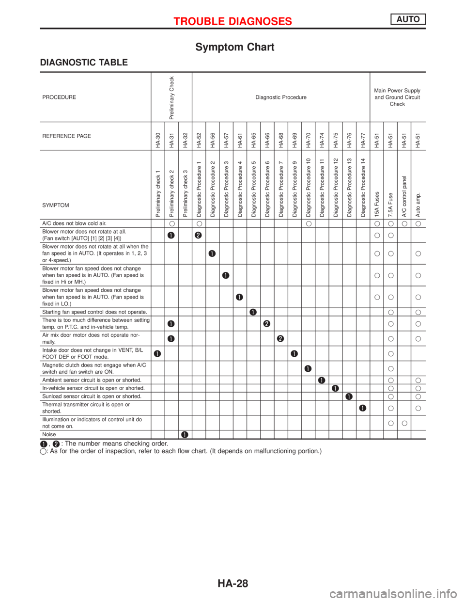
Symptom Chart
DIAGNOSTIC TABLE
PROCEDURE
Preliminary Check
Diagnostic ProcedureMain Power Supply
and Ground Circuit
Check
REFERENCE PAGE
HA-30
HA-31
HA-32
HA-52
HA-56
HA-57
HA-61
HA-65
HA-66
HA-68
HA-69
HA-70
HA-74
HA-75
HA-76
HA-77
HA-51
HA-51
HA-51
HA-51
SYMPTOM
Preliminary check 1
Preliminary check 2
Preliminary check 3
Diagnostic Procedure 1
Diagnostic Procedure 2
Diagnostic Procedure 3
Diagnostic Procedure 4
Diagnostic Procedure 5
Diagnostic Procedure 6
Diagnostic Procedure 7
Diagnostic Procedure 9
Diagnostic Procedure 10
Diagnostic Procedure 11
Diagnostic Procedure 12
Diagnostic Procedure 13
Diagnostic Procedure 14
15A Fuses
7.5A Fuse
A/C control panel
Auto amp.
A/C does not blow cold air.q q q qqqq
Blower motor does not rotate at all.
(Fan switch [AUTO] [1] [2] [3] [4])
qq
Blower motor does not rotate at all when the
fan speed is in AUTO. (It operates in 1, 2, 3
or 4-speed.)
qq q
Blower motor fan speed does not change
when fan speed is in AUTO. (Fan speed is
fixed in Hi or MH.)
qq q
Blower motor fan speed does not change
when fan speed is in AUTO. (Fan speed is
fixed in LO.)
qq q
Starting fan speed control does not operate.
qq
There is too much difference between setting
temp. on P.T.C. and in-vehicle temp.
qq
Air mix door motor does not operate nor-
mally.
qq
Intake door does not change in VENT, B/L
FOOT DEF or FOOT mode.
q
Magnetic clutch does not engage when A/C
switch and fan switch are ON.
q
Ambient sensor circuit is open or shorted.
qq
In-vehicle sensor circuit is open or shorted.
qq
Sunload sensor circuit is open or shorted.
qq
Thermal transmitter circuit is open or
shorted.
qq
Illumination or indicators of control unit do
not come on.qq
Noise
,: The number means checking order.
q: As for the order of inspection, refer to each flow chart. (It depends on malfunctioning portion.)
TROUBLE DIAGNOSESAUTO
HA-28
Page 1878 of 2267
Electrical Components Inspection
Ð
Ð
Ð
Ð
Ð
HA-84
HA-93
HA-94
HA-81
HA-51
HA-86
HA-85
HA-86Refer to
EL section.HA-87
HA-98
HA-98
HA-98
HA-98
HA-80
HA-79
HA-70
HA-113Refer to
EC section.
Refer to
EL section.Ð Blower motor
Fan resistor
Control
unit
Air mix door
PBR
Intake door motor
Auto amp.
Ambient sensor
In-vehicle sensor
Sunload sensor
Thermal transmitter
A/C relay
LO relay
ML relay
MH relay
HI relay
Thermo control amp.
Pressure switch/sensor
Com-
pressor
ECM
Illumination system
Harness A/C switch
REC switch
Fan switch
PTC
Magnetic clutch
Thermal protector
q qq qqqqqqqqq q qqqq q
qq qq
q q q q qqqq q
qq q q qq q
qq q q q q q
qq q q qq
qqq qqqqq
qq qqqqq
qqq
q q q qqqqq q
qq
qq
qq
qq
qqqqq
TROUBLE DIAGNOSESAUTO
Symptom Chart (Cont'd)
HA-29
Page 1879 of 2267

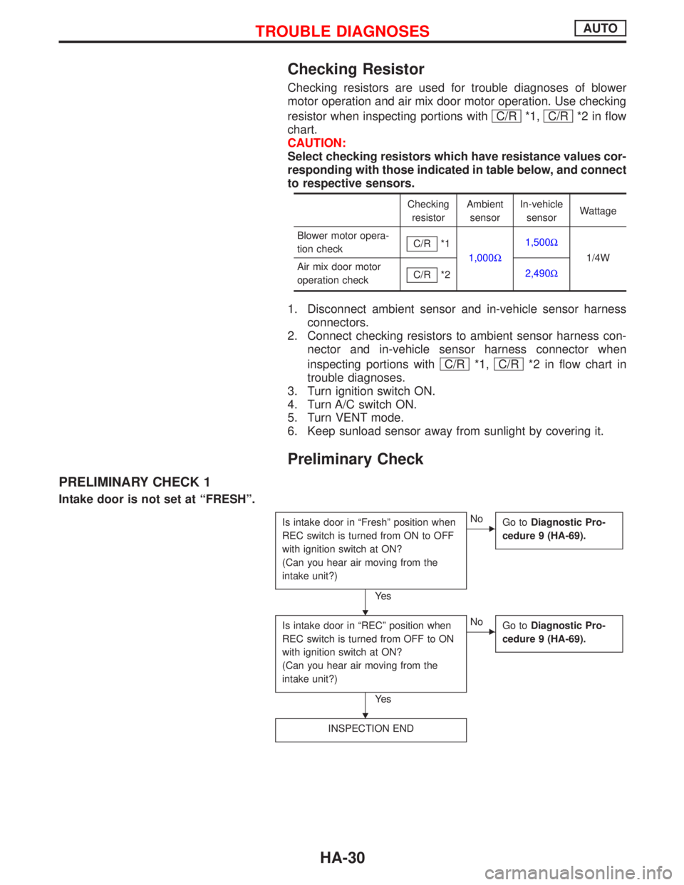
Checking Resistor
Checking resistors are used for trouble diagnoses of blower
motor operation and air mix door motor operation. Use checking
resistor when inspecting portions with C/R
*1, C/R*2 in flow
chart.
CAUTION:
Select checking resistors which have resistance values cor-
responding with those indicated in table below, and connect
to respective sensors.
Checking
resistorAmbient
sensorIn-vehicle
sensorWattage
Blower motor opera-
tion checkC/R
*1
1,000W1,500W
1/4W
Air mix door motor
operation checkC/R
*22,490W
1. Disconnect ambient sensor and in-vehicle sensor harness
connectors.
2. Connect checking resistors to ambient sensor harness con-
nector and in-vehicle sensor harness connector when
inspecting portions with C/R
*1, C/R*2 in flow chart in
trouble diagnoses.
3. Turn ignition switch ON.
4. Turn A/C switch ON.
5. Turn VENT mode.
6. Keep sunload sensor away from sunlight by covering it.
Preliminary Check
PRELIMINARY CHECK 1
Intake door is not set at ªFRESHº.
Is intake door in ªFreshº position when
REC switch is turned from ON to OFF
with ignition switch at ON?
(Can you hear air moving from the
intake unit?)
Ye s
ENo
Go toDiagnostic Pro-
cedure 9 (HA-69).
Is intake door in ªRECº position when
REC switch is turned from OFF to ON
with ignition switch at ON?
(Can you hear air moving from the
intake unit?)
Ye s
ENo
Go toDiagnostic Pro-
cedure 9 (HA-69).
INSPECTION END
H
H
TROUBLE DIAGNOSESAUTO
HA-30
Page 1888 of 2267
Component Location
NHA290
In-vehicle sensorA/C control
panel
Sunload sensorA/C relay
.Triple-pressure switch
(With dieselengine)
Dual-pressure switch (With GA engine)
Pressure sensor (SRand QG engine)Ambient sensor
Compressor
Blower motor
fan resistor
.Auto amp.
HI.ML.LH.LO
relayBlower fan
motor relay
Compressor
.Ambient sensor
.
A/C relay
.Fuse block (J/B)
.Blower fan motor relaylBehind fuse block (J/B)
.
.Auto amp.
.MH relayLO relay
.ML relay.HI relay
Air mix door motor
Blower motor
Fan resistor.
Intake door motor
Sunload
sensor.
A/C control panel
.
.In-vehicle sensor
.Dual-pressure
switch/sensor
.Triple-pressure switch
Intake door
motor
Air mix
door motor
TROUBLE DIAGNOSESAUTO
HA-39
Page 1890 of 2267
Circuit Diagram Ð Air Conditioner
YHA337
IGNITION SWITCH
ON
FUSE
BLOWER
MOTORINTAKE
DOOR
MOTORTo illumination
systemCOMBINATION
METER
(WATER TEM-
PERATURE
GAUGE)IGNITION SWITCH
ON or START
FUSEFUSIBLE
LINKBATTERY
FUSIBLE
LINK
COOLING
FA N
MOTOR-1
THERMO
CONTROL
AMPLIFIERAIR CONDI-
TIONER
RELAYCOOLING
FA N
RELAY-1COOLING
FA N
RELAY-2COOLING
FA N
RELAY-3
TRIPLE-
PRESSURE
SWITCH
COOL-
ING FAN
RELAY-1
DUAL-
PRESSURE
SWITCH
COOLING
FA N
MOTOR-1COOLING
FA N
MOTOR-2COOLING
FA N
MOTOR-2
: With gasoline engine
: With diesel engine
: With GA engine
: With SR engine or
QG engine
: With GA engine or
diesel engine IACV-FIDC
SOLENOID
VA LV E THERMAL PRO-
TECTOR
COMPRESSOR THERMAL
TRANSMITTER A/C AUTO AMPIN-
VEHICLE
SENSORA/C CON-
TROL
PANEL
REFRIGENT
PRESSURE
SENSOR AMBIENT
SENSOR SUN LOAD
SENSOR A/C HIGH
RELAY
A/C MH
RELAY
A/C ML
RELAY
A/C LOW
RELAY FA N
RESISTOR
AIR MIX
DOOR
MOTOR
TROUBLE DIAGNOSESAUTO
HA-41
Page 1896 of 2267
WITH SR ENGINE or QG ENGINE
YHA342
Preceding
page
FUSE
BLOCK
(J/B)
AIR
CONDITIONER
RELAY
REFRIGERANT
PRESSURE
SENSOR
COMPRESSOR
ECM
REFER TO THE FOLLOWING
FUSE BLOCK - Junction Box (J/B)
FUSE BLOCK - Junction Box (J/B)
ELECTRICAL UNITS
CVT models
MT models
TROUBLE DIAGNOSESAUTO
Wiring Diagram Ð A/C Ð (Cont'd)
HA-47