1999 NISSAN PRIMERA belt
[x] Cancel search: beltPage 1678 of 2267
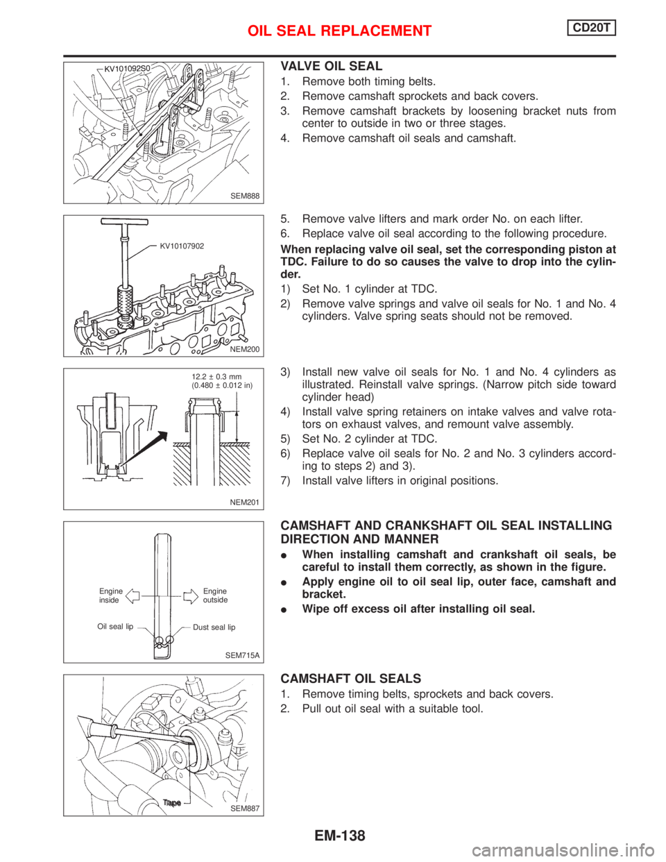
VALVE OIL SEAL
1. Remove both timing belts.
2. Remove camshaft sprockets and back covers.
3. Remove camshaft brackets by loosening bracket nuts from
center to outside in two or three stages.
4. Remove camshaft oil seals and camshaft.
5. Remove valve lifters and mark order No. on each lifter.
6. Replace valve oil seal according to the following procedure.
When replacing valve oil seal, set the corresponding piston at
TDC. Failure to do so causes the valve to drop into the cylin-
der.
1) Set No. 1 cylinder at TDC.
2) Remove valve springs and valve oil seals for No. 1 and No. 4
cylinders. Valve spring seats should not be removed.
3) Install new valve oil seals for No. 1 and No. 4 cylinders as
illustrated. Reinstall valve springs. (Narrow pitch side toward
cylinder head)
4) Install valve spring retainers on intake valves and valve rota-
tors on exhaust valves, and remount valve assembly.
5) Set No. 2 cylinder at TDC.
6) Replace valve oil seals for No. 2 and No. 3 cylinders accord-
ing to steps 2) and 3).
7) Install valve lifters in original positions.
CAMSHAFT AND CRANKSHAFT OIL SEAL INSTALLING
DIRECTION AND MANNER
IWhen installing camshaft and crankshaft oil seals, be
careful to install them correctly, as shown in the figure.
IApply engine oil to oil seal lip, outer face, camshaft and
bracket.
IWipe off excess oil after installing oil seal.
CAMSHAFT OIL SEALS
1. Remove timing belts, sprockets and back covers.
2. Pull out oil seal with a suitable tool.
SEM888
NEM200 KV10107902
NEM201 12.2 0.3 mm
(0.480 0.012 in)
SEM715A Engine
inside
Oil seal lipEngine
outside
Dust seal lip
.SEM887 Tape
OIL SEAL REPLACEMENTCD20T
EM-138
Page 1679 of 2267
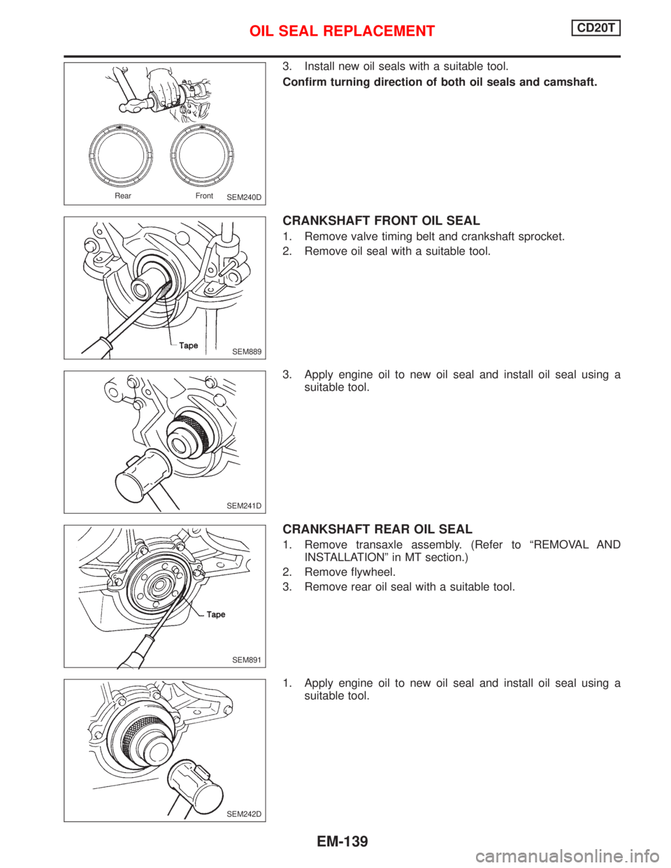
3. Install new oil seals with a suitable tool.
Confirm turning direction of both oil seals and camshaft.
CRANKSHAFT FRONT OIL SEAL
1. Remove valve timing belt and crankshaft sprocket.
2. Remove oil seal with a suitable tool.
3. Apply engine oil to new oil seal and install oil seal using a
suitable tool.
CRANKSHAFT REAR OIL SEAL
1. Remove transaxle assembly. (Refer to ªREMOVAL AND
INSTALLATIONº in MT section.)
2. Remove flywheel.
3. Remove rear oil seal with a suitable tool.
1. Apply engine oil to new oil seal and install oil seal using a
suitable tool.
SEM240D Rear Front
SEM889
SEM241D
SEM891
SEM242D
OIL SEAL REPLACEMENTCD20T
EM-139
Page 1681 of 2267
Removal
1. Drain coolant and disconnect front exhaust pipe from manifold.
2. Remove water hoses, air duct and intake manifold.
3. Remove heat shield and exhaust manifold.
4. Remove rocker cover and injection tubes.
5. Remove both timing belts.
Set No. 1 cylinder at TDC on its compression stroke. Refer to
ªTIMING BELTº (EM-134).
After timing belts have been removed, do not rotate crankshaft
and/or camshaft separately as valves will hit piston heads.
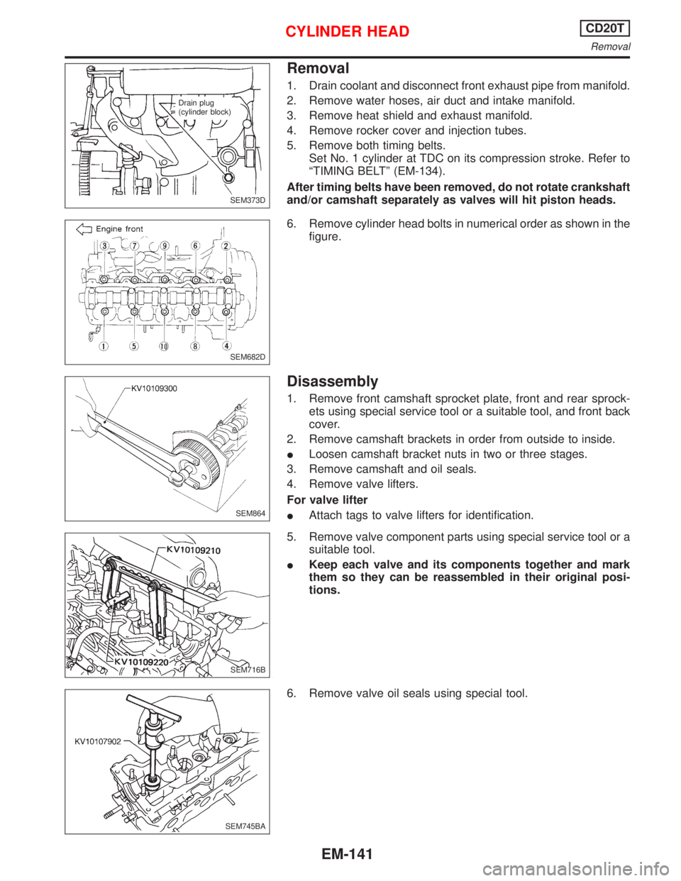
6. Remove cylinder head bolts in numerical order as shown in the
figure.
Disassembly
1. Remove front camshaft sprocket plate, front and rear sprock-
ets using special service tool or a suitable tool, and front back
cover.
2. Remove camshaft brackets in order from outside to inside.
ILoosen camshaft bracket nuts in two or three stages.
3. Remove camshaft and oil seals.
4. Remove valve lifters.
For valve lifter
IAttach tags to valve lifters for identification.
5. Remove valve component parts using special service tool or a
suitable tool.
IKeep each valve and its components together and mark
them so they can be reassembled in their original posi-
tions.
6. Remove valve oil seals using special tool.
SEM373D Drain plug
(cylinder block)
SEM682D
SEM864
SEM716B
SEM745BA
CYLINDER HEADCD20T
Removal
EM-141
Page 1703 of 2267
WARNING:
ISituate vehicle on a flat and solid surface.
IPlace chocks at front and back of rear wheels.
IDo not remove engine until exhaust system has com-
pletely cooled down.
IFor safety during subsequent steps, the tension of wires
should be slackened against the engine.
IBefore removing front axle from transaxle, place safety
stands under designated front supporting points. Refer to
GI section for lifting points and towing.
IBe sure to hoist engine and transaxle in a safe manner.
IFor engines not equipped with engine slingers, attach
proper slingers and bolts described in PARTS CATALOG
or Eurofast.
CAUTION:
IWhen lifting engine, be careful not to strike adjacent parts,
especially accelerator wire casing, brake lines, and brake
master cylinder.
IAlways use engine slingers when hoisting the engine.
IWhen removing drive shaft, be careful not to damage tran-
saxle oil seal.
1. Remove engine undercovers and splash covers.
2. Remove front exhaust tube.
3. Disconnect lower water hose from radiator and drain coolant.
4. Drain transaxle oil.
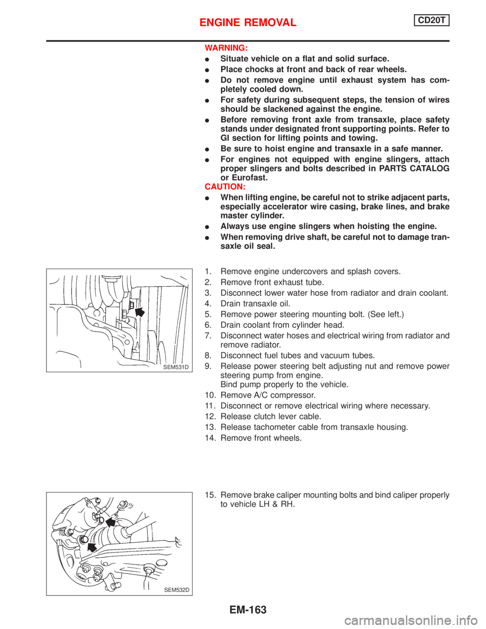
5. Remove power steering mounting bolt. (See left.)
6. Drain coolant from cylinder head.
7. Disconnect water hoses and electrical wiring from radiator and
remove radiator.
8. Disconnect fuel tubes and vacuum tubes.
9. Release power steering belt adjusting nut and remove power
steering pump from engine.
Bind pump properly to the vehicle.
10. Remove A/C compressor.
11. Disconnect or remove electrical wiring where necessary.
12. Release clutch lever cable.
13. Release tachometer cable from transaxle housing.
14. Remove front wheels.
15. Remove brake caliper mounting bolts and bind caliper properly
to vehicle LH & RH.
.SEM531D
SEM532D
ENGINE REMOVALCD20T
EM-163
Page 1707 of 2267
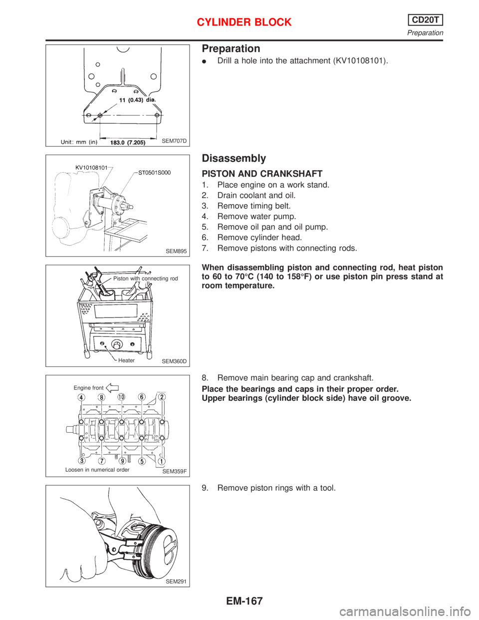
Preparation
IDrill a hole into the attachment (KV10108101).
Disassembly
PISTON AND CRANKSHAFT
1. Place engine on a work stand.
2. Drain coolant and oil.
3. Remove timing belt.
4. Remove water pump.
5. Remove oil pan and oil pump.
6. Remove cylinder head.
7. Remove pistons with connecting rods.
When disassembling piston and connecting rod, heat piston
to 60 to 70ÉC (140 to 158ÉF) or use piston pin press stand at
room temperature.
8. Remove main bearing cap and crankshaft.
Place the bearings and caps in their proper order.
Upper bearings (cylinder block side) have oil groove.
9. Remove piston rings with a tool.
SEM707D
SEM895
SEM360D Piston with connecting rod
Heater
SEM359F Engine front
Loosen in numerical order
SEM291
CYLINDER BLOCKCD20T
Preparation
EM-167
Page 1796 of 2267
GENERAL INFORMATION
SECTION
GI
CONTENTS
MODIFICATIONS........................................................... 2
PRECAUTIONS............................................................. 3
Supplemental Restraint System (SRS)²AIR
BAG²and²SEAT BELT PRE-TENSIONER²............. 3
Precautions for NATS ................................................ 3
Precautions for Super Lock System .......................... 4
General Precautions .................................................. 4
Precautions for Multiport Fuel Injection System
or Engine Control Module.......................................... 6
Precautions for Three Way Catalyst.......................... 6
Precautions for Turbocharger .................................... 6
Precautions for Engine Oils ....................................... 6
Precautions for Fuel .................................................. 7
Precautions for Air Conditioning ................................ 8
HOW TO USE THIS MANUAL...................................... 9
HOW TO READ WIRING DIAGRAMS......................... 11
Sample/Wiring Diagram - EXAMPL - ....................... 11
Description ............................................................... 13
Wiring Diagram Codes (Cell Codes) ....................... 20
HOW TO CHECK TERMINAL..................................... 21
How to Probe Connectors ....................................... 21
How to Check Enlarged Contact Spring of
Terminal ................................................................... 22
Waterproof Connector Inspection ............................ 23
Terminal Lock Inspection ......................................... 23HOW TO PERFORM EFFICIENT DIAGNOSIS FOR
AN ELECTRICAL INCIDENT...................................... 24
Work Flow ................................................................ 24
Incident Simulation Tests ......................................... 25
Circuit Inspection ..................................................... 29
HOW TO FOLLOW TROUBLE DIAGNOSES............ 35
How to Follow Test Groups in Trouble Diagnoses .. 35
CONSULT-II CHECKING SYSTEM............................. 39
Function and System Application ............................ 39
Nickel Metal Hydride Battery Replacement............. 39
Checking Equipment................................................ 39
CONSULT-II Data Link Connector (DLC) Circuit .... 40
IDENTIFICATION INFORMATION............................... 41
Model Variation ........................................................ 41
Identification Number ............................................... 43
Dimensions .............................................................. 45
Wheels and Tires ..................................................... 45
LIFTING POINTS AND TOW TRUCK TOWING......... 46
Preparation .............................................................. 46
Board-on Lift ............................................................ 46
Garage Jack and Safety Stand ............................... 47
2-pole Lift ................................................................. 48
Tow Truck Towing .................................................... 49
TIGHTENING TORQUE OF STANDARD BOLTS...... 50
ISO 15031-2 TERMINOLOGY LIST............................ 51
ISO 15031-2 Terminology List ................................. 51
GI
Page 1798 of 2267
Observe the following precautions to ensure safe and
proper servicing.
Supplemental Restraint System (SRS) ªAIR
BAGº and ªSEAT BELT PRE-TENSIONERº
The Supplemental Restraint System ªAir Bagº and ªSeat Belt
Pre-tensionerº, used along with a seat belt, help to reduce the
risk or severity of injury to the driver and front passenger in a
frontal collision. The Supplemental Restraint System consists of
air bag modules (located in the center of the steering wheel and
on the instrument panel on the passenger side), seat belt pre-
tensioners, a diagnosis sensor unit, warning lamp, wiring har-
ness and spiral cable.
If the vehicle is equipped with side air bag as the Supplemental
Restraint System, the side air bag used along with the seat belt
helps to reduce the risk or severity of injury to the driver and front
passenger in a side collision. The side air bag consists of air bag
modules (located in the outer side of front seats), satellite sensor,
diagnosis sensor unit (which is one of components of air bags for
a frontal collision), wiring harness, warning lamp (which is one of
components of air bags for a frontal collision).
WARNING:
lTo avoid rendering the SRS inoperative, (which could
increase the risk of personal injury or death in the event
of a collision which would result in air bag inflation) all
maintenance must be performed by an authorized
NISSAN dealer.
lImproper maintenance, including incorrect removal and
installation of the SRS, can lead to personal injury
caused by unintentional activation of the system.
lDo not use electrical test equipment on any circuit
related to the SRS unless instructed to do so in this
Service Manual. SRS wiring harnesses are covered with
yellow insulation (either just before the harness connec-
tors or for the complete harness), for easy identification.
Precautions for NATS
NATS (Nissan Anti-Theft System)
NATS will immobilize the engine if someone tries to start it with-
out the registered key of NATS.
Both of the originally supplied ignition key IDs have been NATS
registered.
The NATS security indicator is located on the instrument panel.
The indicator flashes when the ignition switch is in ªLOCKº or
ªAccº position. Therefore, NATS warns outsiders that the vehicle
is equipped with the anti-theft system.
lWhen NATS detects trouble, the malfunction indicator (MI)
flashes.
This flashing indicates that the anti-theft is not functioning, so
prompt service is required.
lWhen servicing NATS (trouble diagnoses, system initialisa-
tion and additional registration of other NATS ignition key
IDs), CONSULT-II hardware and CONSULT-II NATS soft-
ware is necessary.
SGI916
PRECAUTIONS
GI-3
Page 1850 of 2267
HEATER &
AIR CONDITIONER
SECTION
HA
CONTENTS
PRECAUTIONS AND PREPARATION.......................... 3
Supplemental Restraint System (SRS)²AIR
BAG²and²SEAT BELT PRE-TENSIONER²............. 3
Precautions for Working with HFC-134a (R-134a) ... 3
General Refrigerant Precautions ............................... 4
Precautions for Refrigerant Connection .................... 4
Precautions for Servicing Compressor ...................... 7
Special Service Tools ................................................ 7
HFC-134a (R-134a) Service Tools and
Equipment .................................................................. 8
Precautions for Service Equipment ......................... 10
DESCRIPTION............................................................. 12
Refrigeration Cycle .................................................. 12
CSV613 Variable Displacement Compressor.......... 14
Component Layout .................................................. 18
HEATER
DESCRIPTION............................................................. 19
Control Operation .................................................... 19
Air Flow .................................................................... 19
AUTO
DESCRIPTION............................................................. 20
Introduction .............................................................. 20
Features ................................................................... 20
Control Operation .................................................... 21
Discharge Air Flow................................................... 23
HEATER
TROUBLE DIAGNOSES............................................. 24
Operational Check ................................................... 24
AUTO
TROUBLE DIAGNOSES............................................. 26
How to Perform Trouble Diagnoses for Quick
and Accurate Repair ................................................ 26
Symptom Chart ........................................................ 28
Checking Resistor.................................................... 30
Preliminary Check.................................................... 30
Performance Test Diagnoses .................................. 33
A/C Performance Chart ........................................... 35
Trouble Diagnoses for Abnormal Pressure ............. 36
Component Location................................................ 39
Wiring Diagram - HEATER -.................................... 40
Circuit Diagram - Air Conditioner............................. 41
Wiring Diagram - A/C - ............................................ 42
Main Power Supply and Ground Circuit Check ...... 51
Diagnostic Procedure 1 ........................................... 52
Diagnostic Procedure 2: Models with relay type 1.. 54
Diagnostic Procedure 2: Models with relay type 2.. 56
Diagnostic Procedure 3: Models with relay type 1.. 57
Diagnostic Procedure 3: Models with relay type 2.. 59
Diagnostic Procedure 4: Models with relay type 1.. 61
Diagnostic Procedure 4: Models with relay type 2.. 63
Diagnostic Procedure 5 ........................................... 65
Diagnostic Procedure 6 ........................................... 66
Diagnostic Procedure 7 ........................................... 68
Diagnostic Procedure 9 ........................................... 69
Diagnostic Procedure 10 ......................................... 70
Diagnostic Procedure 11 ......................................... 74
Diagnostic Procedure 12 ......................................... 75
Diagnostic Procedure 13 ......................................... 76
Diagnostic Procedure 14 ......................................... 77
Electrical Components Inspection ........................... 78
Control Panel System .............................................. 80
HA