1999 NISSAN PRIMERA belt
[x] Cancel search: beltPage 1852 of 2267
Supplemental Restraint System (SRS) ªAIR
BAGº and ªSEAT BELT PRE-TENSIONERº
The Supplemental Restraint System such as ªAIR BAGº and ªSEAT BELT PRE-TENSIONERº used along
with a seat belt, helps to reduce the risk or severity of injury to the driver and front passenger for certain
types of collision. The SRS system composition which is available to NISSAN MODEL P11 is as follows (The
composition varies according to optional equipment):
lFor a frontal collision
The Supplemental Restraint System consists of driver's air bag module (located in the center of the
steering wheel), front passenger's air bag module (located on the instrument panel on passenger's side),
seat belt pre-tensioners, a diagnosis sensor unit, warning lamp, wiring harness and spiral cable.
lFor a side collision
The Supplemental Restraint System consists of front side air bag module (located in the outer side of
front seat), satellite sensor, diagnosis sensor unit (one of components of air bags for a frontal collision),
wiring harness, warning lamp (one of components of air bags for a frontal collision).
Information necessary to service the system safely is included in theRS sectionof this Service Manual.
WARNING:
lTo avoid rendering the SRS inoperative, which could increase the risk of personal injury or death
in the event of a collision which would result in air bag inflation, all maintenance must be per-
formed by an authorized NISSAN dealer.
lImproper maintenance, including incorrect removal and installation of the SRS, can lead to per-
sonal injury caused by unintentional activation of the system. For removal of Spiral Cable and
Air Bag Module, see the RS section.
lDo not use electrical test equipment on any circuit related to the SRS unless instructed to in this
Service Manual. Spiral cable and wiring harnesses covered with yellow insulation or tape either
just before the harness connectors or for the complete harness are related to the SRS.
Precautions for Working with HFC-134a
(R-134a)
WARNING:
lCFC-12 (R-12) refrigerant and HFC-134a (R-134a) refrigerant are not compatible. These refriger-
ants must never be mixed, even in the smallest amounts. If the refrigerants are mixed, compres-
sor failure is likely to occur.
lUse only specified lubricant for the HFC-134a (R-134a) A/C system and HFC-134a (R-134a)
components. If lubricant other than that specified is used, compressor failure is likely to occur.
lThe specified HFC-134a (R-134a) lubricant rapidly absorbs moisture from the atmosphere. The
following handling precautions must be observed:
a: When removing refrigerant components from a vehicle, immediately cap (seal) the compo-
nent to minimize the entry of moisture from the atmosphere.
b: When installing refrigerant components to a vehicle, do not remove the caps (unseal) until
just before connecting the components. Connect all refrigerant loop components as quickly
as possible to minimize the entry of moisture into system.
c: Only use the specified lubricant from a sealed container. Immediately reseal containers of
lubricant. Without proper sealing, lubricant will become moisture saturated and should not
be used.
d: Avoid breathing A/C refrigerant and lubricant vapor or mist. Exposure may irritate eyes, nose
and throat. Remove R-134a from the A/C system, using certified service equipment meeting
requirements of SAE J2210 (R-134a recycling equipment), or J2209 (R-134a recovery equip-
ment). If accidental system discharge occurs, ventilate work area before resuming service.
Additional health and safety information may be obtained from refrigerant and lubricant
manufacturers.
e: Do not allow lubricant (Nissan A/C System Oil Type S or type R) to come in contact with sty-
rofoam parts. Damage may result.
PRECAUTIONS AND PREPARATION
HA-3
Page 1880 of 2267
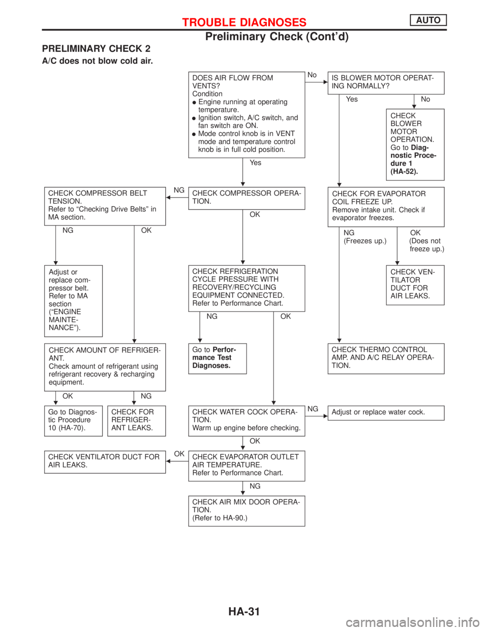
PRELIMINARY CHECK 2
A/C does not blow cold air.
DOES AIR FLOW FROM
VENTS?
Condition
lEngine running at operating
temperature.
lIgnition switch, A/C switch, and
fan switch are ON.
lMode control knob is in VENT
mode and temperature control
knob is in full cold position.
Ye s
ENo
IS BLOWER MOTOR OPERAT-
ING NORMALLY?
Ye s N o
CHECK
BLOWER
MOTOR
OPERATION.
Go toDiag-
nostic Proce-
dure 1
(HA-52).
CHECK COMPRESSOR BELT
TENSION.
Refer to ªChecking Drive Beltsº in
MA section.
NG OK
FNG
CHECK COMPRESSOR OPERA-
TION.
OKCHECK FOR EVAPORATOR
COIL FREEZE UP.
Remove intake unit. Check if
evaporator freezes.
NG
(Freezes up.)OK
(Does not
freeze up.)
Adjust or
replace com-
pressor belt.
Refer to MA
section
(ªENGINE
MAINTE-
NANCEº).
CHECK REFRIGERATION
CYCLE PRESSURE WITH
RECOVERY/RECYCLING
EQUIPMENT CONNECTED.
Refer to Performance Chart.
NG OKCHECK VEN-
TILATOR
DUCT FOR
AIR LEAKS.
CHECK AMOUNT OF REFRIGER-
ANT.
Check amount of refrigerant using
refrigerant recovery & recharging
equipment.
OK NGGo toPerfor-
mance Test
Diagnoses.
CHECK THERMO CONTROL
AMP. AND A/C RELAY OPERA-
TION.
Go to Diagnos-
tic Procedure
10 (HA-70).CHECK FOR
REFRIGER-
ANT LEAKS.CHECK WATER COCK OPERA-
TION.
Warm up engine before checking.
OK
ENG
Adjust or replace water cock.
CHECK VENTILATOR DUCT FOR
AIR LEAKS.FOK
CHECK EVAPORATOR OUTLET
AIR TEMPERATURE.
Refer to Performance Chart.
NG
CHECK AIR MIX DOOR OPERA-
TION.
(Refer to HA-90.)
H
HH
HHH
HHH
HHH
H
H
TROUBLE DIAGNOSESAUTO
Preliminary Check (Cont'd)
HA-31
Page 1881 of 2267
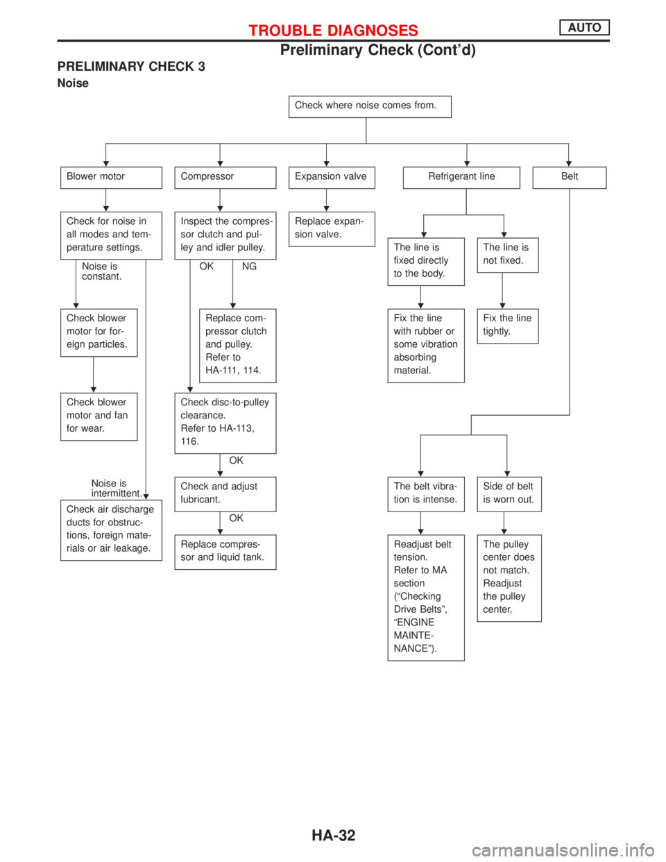
PRELIMINARY CHECK 3
Noise
Check where noise comes from.
Blower motorCompressorExpansion valveRefrigerant lineBelt
Check for noise in
all modes and tem-
perature settings.
Noise is
constant.Inspect the compres-
sor clutch and pul-
ley and idler pulley.OK NGReplace expan-
sion valve.
The line is
fixed directly
to the body.The line is
not fixed.
Check blower
motor for for-
eign particles.Replace com-
pressor clutch
and pulley.
Refer to
HA-111, 114.Fix the line
with rubber or
some vibration
absorbing
material.Fix the line
tightly.
Check blower
motor and fan
for wear.Check disc-to-pulley
clearance.
Refer to HA-113,
116.
OK
Noise is
intermittent.
Check air discharge
ducts for obstruc-
tions, foreign mate-
rials or air leakage.Check and adjust
lubricant.
OKThe belt vibra-
tion is intense.
Side of belt
is worn out.
Replace compres-
sor and liquid tank.Readjust belt
tension.
Refer to MA
section
(ªChecking
Drive Beltsº,
ªENGINE
MAINTE-
NANCEº).The pulley
center does
not match.
Readjust
the pulley
center.
HHHHH
HHH
HH
HHHH
HH
H
HHH
HHH
TROUBLE DIAGNOSESAUTO
Preliminary Check (Cont'd)
HA-32
Page 1883 of 2267
pA
Malfunctioning blower motor fanMalfunctioning electrical circuitMalfunctioning blower motor inter-
nal circuit
Loose fan/Improper contact of fan
and case/Deformed fanDiscontinued wiring or component
circuits or poor connection/
Malfunctioning resistor, amplifier,
etc./ Burned out fuse or low bat-
tery voltage.
pB
Magnet clutch does not engage.Magnet clutch slippingBelt slipping
CHECK MAGNET CLUTCH
(coil circuit, disc-to-pulley clear-
ance).CHECK COMPRESSOR BELT
AND BELT TENSION.
CHECK ELECTRICAL CIRCUIT
(wiring, components circuit).EMalfunctioning internal parts of
clutch, compressor
CHECK ACTIVATION OF
SAFETY/PROTECTION DEVICES
(such as pressure switch, etc.).EForeign particles on clutch fric-
tional surface or excessive disc
clearance
EMalfunctioning electrical circuit
(poor connection, low battery
voltage, etc.)
HHH
HH
HHH
HH
H
H
TROUBLE DIAGNOSESAUTO
Performance Test Diagnoses (Cont'd)
HA-34
Page 1960 of 2267
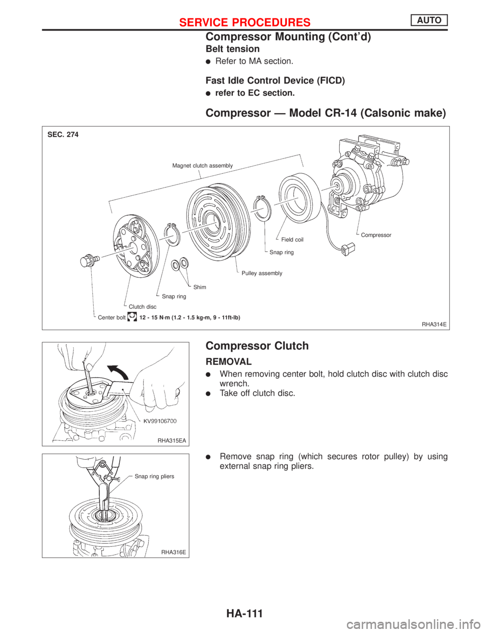
Belt tension
lRefer to MA section.
Fast Idle Control Device (FICD)
lrefer to EC section.
Compressor Ð Model CR-14 (Calsonic make)
Compressor Clutch
REMOVAL
lWhen removing center bolt, hold clutch disc with clutch disc
wrench.
lTake off clutch disc.
lRemove snap ring (which secures rotor pulley) by using
external snap ring pliers.
RHA314E Magnet clutch assembly
Compressor
Field coil
Snap ring
Pulley assembly
Clutch discShim
Snap ring
Center bolt12 - 15 N´m (1.2 - 1.5 kg-m,9-11ft-lb)
SEC. 274
RHA315EA
RHA316E Snap ring pliers
SERVICE PROCEDURESAUTO
Compressor Mounting (Cont'd)
HA-111
Page 1967 of 2267
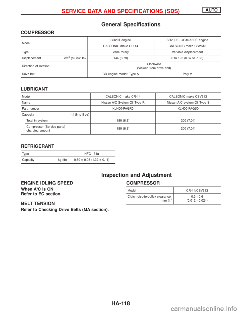
General Specifications
COMPRESSOR
ModelCD20T engine SR20DE, QG16×18DE engine
CALSONIC make CR-14 CALSONIC make CSV613
Type Vane rotary Variable displacement
Displacement cm
3(cu in)/Rev 144 (8.79) 6 to 125 (0.37 to 7.63)
Direction of rotationClockwise
(Viewed from drive end)
Drive belt CD engine model: Type A Poly V
LUBRICANT
Model CALSONIC make CR-14 CALSONIC make CSV613
Name Nissan A/C System Oil Type R Nissan A/C system Oil Type S
Part number KLH00-PAGR0 KLH00-PAGS0
Capacity m(Imp fl oz)
Total in system 180 (6.3) 200 (7.04)
Compressor (Service parts)
charging amount180 (6.3) 200 (7.04)
REFRIGERANT
Type HFC-134a
Capacity kg (lb) 0.60 0.05 (1.32 0.11)
Inspection and Adjustment
ENGINE IDLING SPEED
When A/C is ON
Refer to EC section.
BELT TENSION
Refer to Checking Drive Belts (MA section).
COMPRESSOR
Model CR-14/CSV613
Clutch disc-to-pulley clearance
mm (in)0.3 - 0.6
(0.012 - 0.024)
SERVICE DATA AND SPECIFICATIONS (SDS)AUTO
HA-118
Page 1970 of 2267
Combination meter removal and instal-
lation - See Instrument panel ......................BT-15
Combination switch .........................................EL-64
Combustion chamber replacement ..............EM-146
Component location (cool box) ......................HA-39
Compression pressure ..........EM-69, 126, 188, 196
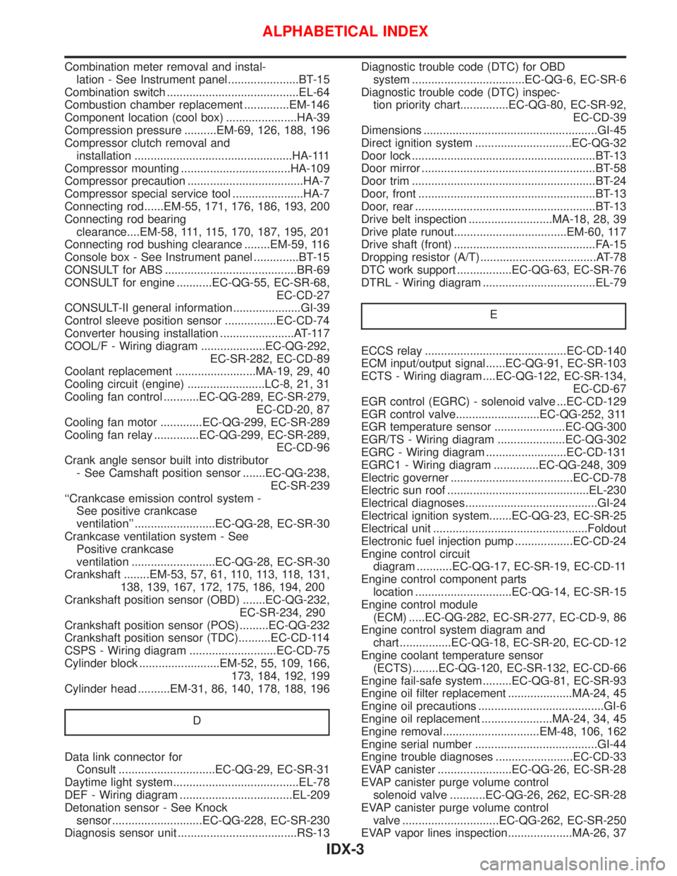
Compressor clutch removal and
installation .................................................HA-111
Compressor mounting ..................................HA-109
Compressor precaution ....................................HA-7
Compressor special service tool ......................HA-7
Connecting rod......EM-55, 171, 176, 186, 193, 200
Connecting rod bearing
clearance....EM-58, 111, 115, 170, 187, 195, 201
Connecting rod bushing clearance ........EM-59, 116
Console box - See Instrument panel ..............BT-15
CONSULT for ABS .........................................BR-69
CONSULT for engine ...........EC-QG-55, EC-SR-68,
EC-CD-27
CONSULT-II general information .....................GI-39
Control sleeve position sensor ................EC-CD-74
Converter housing installation .......................AT-117
COOL/F - Wiring diagram ....................EC-QG-292,
EC-SR-282, EC-CD-89
Coolant replacement .........................MA-19, 29, 40
Cooling circuit (engine) ........................LC-8, 21, 31
Cooling fan control ...........EC-QG-289, EC-SR-279,
EC-CD-20, 87
Cooling fan motor .............EC-QG-299, EC-SR-289
Cooling fan relay ..............EC-QG-299, EC-SR-289,
EC-CD-96
Crank angle sensor built into distributor
- See Camshaft position sensor .......EC-QG-238,
EC-SR-239
‘‘Crankcase emission control system -
See positive crankcase
ventilation’’ .........................EC-QG-28, EC-SR-30
Crankcase ventilation system - See
Positive crankcase
ventilation ..........................EC-QG-28, EC-SR-30
Crankshaft ........EM-53, 57, 61, 110, 113, 118, 131,
138, 139, 167, 172, 175, 186, 194, 200
Crankshaft position sensor (OBD) .......EC-QG-232,
EC-SR-234, 290
Crankshaft position sensor (POS).........EC-QG-232
Crankshaft position sensor (TDC)..........EC-CD-114
CSPS - Wiring diagram ...........................EC-CD-75
Cylinder block .........................EM-52, 55, 109, 166,
173, 184, 192, 199
Cylinder head ..........EM-31, 86, 140, 178, 188, 196
D
Data link connector for
Consult ..............................EC-QG-29, EC-SR-31
Daytime light system.......................................EL-78
DEF - Wiring diagram ...................................EL-209
Detonation sensor - See Knock
sensor ............................EC-QG-228, EC-SR-230
Diagnosis sensor unit .....................................RS-13Diagnostic trouble code (DTC) for OBD
system ...................................EC-QG-6, EC-SR-6
Diagnostic trouble code (DTC) inspec-
tion priority chart...............EC-QG-80, EC-SR-92,
EC-CD-39
Dimensions ......................................................GI-45
Direct ignition system ..............................EC-QG-32
Door lock .........................................................BT-13
Door mirror ......................................................BT-58
Door trim .........................................................BT-24
Door, front .......................................................BT-13
Door, rear ........................................................BT-13
Drive belt inspection ..........................MA-18, 28, 39
Drive plate runout...................................EM-60, 117
Drive shaft (front) ............................................FA-15
Dropping resistor (A/T) ....................................AT-78
DTC work support .................EC-QG-63, EC-SR-76
DTRL - Wiring diagram ...................................EL-79
E
ECCS relay ............................................EC-CD-140
ECM input/output signal......EC-QG-91, EC-SR-103
ECTS - Wiring diagram ....EC-QG-122, EC-SR-134,
EC-CD-67
EGR control (EGRC) - solenoid valve ...EC-CD-129
EGR control valve..........................EC-QG-252, 311
EGR temperature sensor ......................EC-QG-300
EGR/TS - Wiring diagram .....................EC-QG-302
EGRC - Wiring diagram .........................EC-CD-131
EGRC1 - Wiring diagram ..............EC-QG-248, 309
Electric governer ......................................EC-CD-78
Electric sun roof ............................................EL-230
Electrical diagnoses.........................................GI-24
Electrical ignition system.......EC-QG-23, EC-SR-25
Electrical unit ................................................Foldout
Electronic fuel injection pump ..................EC-CD-24
Engine control circuit
diagram ...........EC-QG-17, EC-SR-19, EC-CD-11
Engine control component parts
location ..............................EC-QG-14, EC-SR-15
Engine control module
(ECM) .....EC-QG-282, EC-SR-277, EC-CD-9, 86
Engine control system diagram and
chart ................EC-QG-18, EC-SR-20, EC-CD-12
Engine coolant temperature sensor
(ECTS) ........EC-QG-120, EC-SR-132, EC-CD-66
Engine fail-safe system .........EC-QG-81, EC-SR-93
Engine oil filter replacement ....................MA-24, 45
Engine oil precautions .......................................GI-6
Engine oil replacement ......................MA-24, 34, 45
Engine removal..............................EM-48, 106, 162
Engine serial number ......................................GI-44
Engine trouble diagnoses ........................EC-CD-33
EVAP canister .......................EC-QG-26, EC-SR-28
EVAP canister purge volume control
solenoid valve ...........EC-QG-26, 262, EC-SR-28
EVAP canister purge volume control
valve ..............................EC-QG-262, EC-SR-250
EVAP vapor lines inspection....................MA-26, 37
ALPHABETICAL INDEX
IDX-3
Page 1971 of 2267
Evaporative emission (EVAP)
system ...............................EC-QG-25, EC-SR-27
Exhaust gas recirculation (EGR)
valve...........................................EC-QG-244, 305
Exhaust system ................................................FE-9
Exhaust system inspection ............................MA-48
Exterior ............................................................BT-31
F
FCUT - Wiring diagram ..........................EC-CD-101
F/FOG - Wiring diagram................................EL-110
Final drive (FF M/T) ...........................MT-32, 51, 71
Floor trim .........................................................BT-18
Fluid temperature sensor (A/T) .......................AT-94
Fluids..............................................................MA-16
Flywheel (clutch) .............................................CL-14
Flywheel runout..............................EM-60, 117, 177
Fog lamp, front ..............................................EL-110
Fog lamp, rear ...............................................EL-112
F/PUMP - Wiring
diagram..........................EC-QG-338, EC-SR-317
Freeze frame data ................EC-QG-38, EC-SR-50
Fresh vent door control linkage
adjustment ..................................................HA-83
FRO2 - Wiring diagram ........EC-QG-135, 154, 162,
EC-SR-147, 165, 172
FRO2/H - Wiring
diagram..........................EC-QG-168, EC-SR-177
Front axle ..........................................................FA-9
Front bumper ....................................................BT-5
Front disc brake .............................................BR-23
Front door .......................................................BT-13
Front fog lamp .......................................EL-110, 111
Front fog lamp removal and installation ...........BT-5
Front heated oxygen sensor
(HO2S) ......................................EC-QG-132, 139,
EC-SR-144, 150, 156, 162, 170
Front heated oxygen sensor (HO2S)
heater ............................EC-QG-166, EC-SR-175
Front passenger air bag .................................RS-17
Front seat ........................................................BT-40
Front seat belt ..................................................RS-3
Front suspension ............................................FA-26
Front washer .................................................EL-186
Front wiper ....................................................EL-186
FTS - Wiring diagram ............................EC-CD-105
FUEL - Wiring
diagram .........EC-QG-210, 217, EC-SR-213, 220
Fuel cut control (at no load & high
engine speed)....................EC-QG-25, EC-SR-27
Fuel cut solenoid valve ..........................EC-CD-100
Fuel filter ...............................EC-QG-29, EC-SR-31
Fuel filter replacement .......................MA-23, 33, 43
Fuel gauge ............................................EL-141, 146
Fuel injection system....................EC-QG-208, 215,
EC-SR-212, 218,
EC-CD-15, 18
Fuel injector ......................EC-QG-318, EC-SR-302
Fuel line inspection............................MA-22, 33, 43Fuel precautions ................................................GI-7
Fuel pressure check .............EC-QG-29, EC-SR-31
Fuel pressure regulator .........EC-QG-30, EC-SR-32
Fuel pressure release ...........EC-QG-29, EC-SR-31
Fuel pump .........................EC-QG-336, EC-SR-316
Fuel pump and gauge ......................................FE-7
Fuel pump relay ................EC-QG-336, EC-SR-316
Fuel system ......................................................FE-6
Fuel tank vacuum relief
valve ..................................EC-QG-26, EC-SR-28
Fuel temperature sensor .................EC-CD-17, 104
Fuse ..................................................EL-22, Foldout
Fuse block ....................................................Foldout
Fusible link ........................................EL-22, Foldout
G
Garage jack and safety stand .........................GI-47
Gauges..........................................................EL-138
Gear components (M/T) ...........................MT-16, 49
Generic scan tool (GST) .......EC-QG-66, EC-SR-78
GLOW - Wiring diagram ........................EC-CD-120
Glow plug .........................................EC-CD-15, 118
Glow relay ................................................EC-CD-15
GOVNR - Wiring diagram ........................EC-CD-79
Grille - See Exterior ........................................BT-38
Ground distribution..........................................EL-23
H
H/AIM - Wiring diagram ....................EL-87, 93, 200
Harness connector ............................................EL-6
Harness layout ..............................................EL-368
Hazard warning lamp ....................................EL-117
Headlamp..................................................EL-67, 69
Headlamp aiming control ................................EL-87
Headlamp washer .........................................EL-200
Headlining - See Roof trim .............................BT-25
Heated oxygen sensor (HO2S)
(front) ........................................EC-QG-132, 139,
EC-SR-144, 150, 156, 162, 170
Heated oxygen sensor (HO2S) heater
(front) .............................EC-QG-166, EC-SR-175
Heated oxygen sensor (HO2S) heater
(rear) ..............................EC-QG-203, EC-SR-207
Heated oxygen sensor (rear) ...............EC-QG-171,
EC-SR-180, 187,
194, 201
Heated oxygen sensor inspection ...........MA-27, 38
Heated seat .......................................BT-42, EL-234
HEATER - Wiring diagram .............................HA-40
HFC134a (R134a) system service
procedure ..................................................HA-100
HFC134a (R134a) system service tools ..........HA-8
H/LAMP - Wiring diagram ...............................EL-67
Hood..................................................................BT-5
Horn ..............................................................EL-203
HORN - Wiring diagram ................................EL-203
ALPHABETICAL INDEX
IDX-4