Page 1605 of 2267
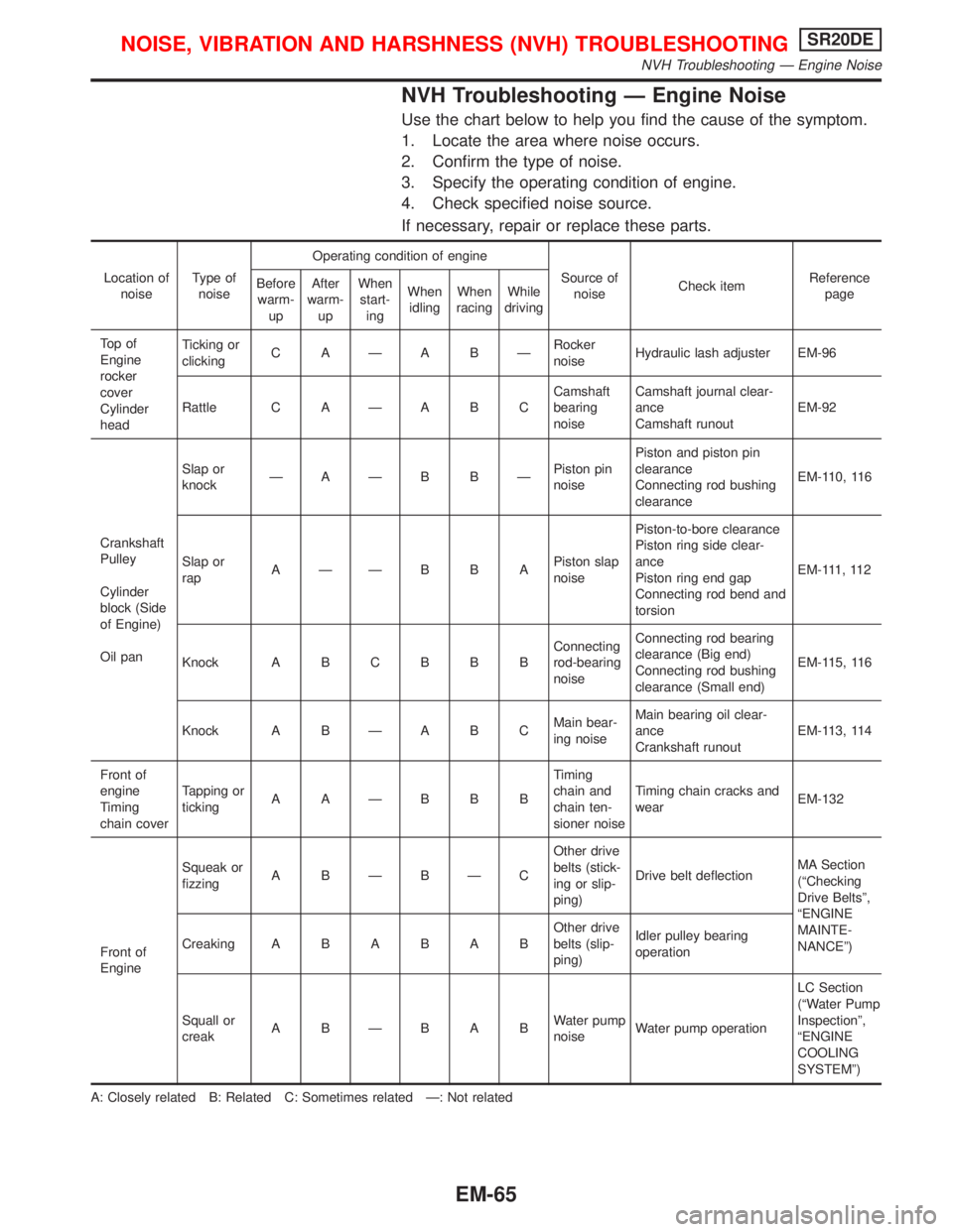
NVH Troubleshooting Ð Engine Noise
Use the chart below to help you find the cause of the symptom.
1. Locate the area where noise occurs.
2. Confirm the type of noise.
3. Specify the operating condition of engine.
4. Check specified noise source.
If necessary, repair or replace these parts.
Location of
noiseType of
noiseOperating condition of engine
Source of
noiseCheck itemReference
page Before
warm-
upAfter
warm-
upWhen
start-
ingWhen
idlingWhen
racingWhile
driving
To p o f
Engine
rocker
cover
Cylinder
headTicking or
clickingC AÐA BÐRocker
noiseHydraulic lash adjuster EM-96
Rattle C A Ð A B CCamshaft
bearing
noiseCamshaft journal clear-
ance
Camshaft runoutEM-92
Crankshaft
Pulley
Cylinder
block (Side
of Engine)
Oil panSlap or
knockÐAÐB BÐPiston pin
noisePiston and piston pin
clearance
Connecting rod bushing
clearanceEM-110, 116
Slap or
rapAÐÐB B APiston slap
noisePiston-to-bore clearance
Piston ring side clear-
ance
Piston ring end gap
Connecting rod bend and
torsionEM-111, 112
Knock A B C B B BConnecting
rod-bearing
noiseConnecting rod bearing
clearance (Big end)
Connecting rod bushing
clearance (Small end)EM-115, 116
Knock A B Ð A B CMain bear-
ing noiseMain bearing oil clear-
ance
Crankshaft runoutEM-113, 114
Front of
engine
Timing
chain coverTapping or
tickingAAÐBBBTiming
chain and
chain ten-
sioner noiseTiming chain cracks and
wearEM-132
Front of
EngineSqueak or
fizzingA BÐBÐCOther drive
belts (stick-
ing or slip-
ping)Drive belt deflectionMA Section
(ªChecking
Drive Beltsº,
ªENGINE
MAINTE-
NANCEº) CreakingABABABOther drive
belts (slip-
ping)Idler pulley bearing
operation
Squall or
creakABÐBABWater pump
noiseWater pump operationLC Section
(ªWater Pump
Inspectionº,
ªENGINE
COOLING
SYSTEMº)
A: Closely related B: Related C: Sometimes related Ð: Not related
NOISE, VIBRATION AND HARSHNESS (NVH) TROUBLESHOOTINGSR20DE
NVH Troubleshooting Ð Engine Noise
EM-65
Page 1616 of 2267
CAUTION:
IAfter removing timing chain, do not turn crankshaft and
camshaft separately, or valves will strike piston heads.
IWhen installing chain tensioner, oil seals, or other sliding
parts, lubricate contacting surfaces with new engine oil.
IApply new engine oil to bolt threads and seat surfaces
when installing camshaft sprocket and crankshaft pulley.
RemovalNLEM01261. Remove engine under cover.
2. Remove front RH wheel and engine side cover.
3. Drain coolant by removing cylinder block drain plug and lower
radiator hose. Refer to MA-29, ªChanging Engine Coolantº.
4. Remove drive belts and water pump pulley.
5. Disconnect the following parts:
IVacuum hoses
IWires
IHarness
IConnectors
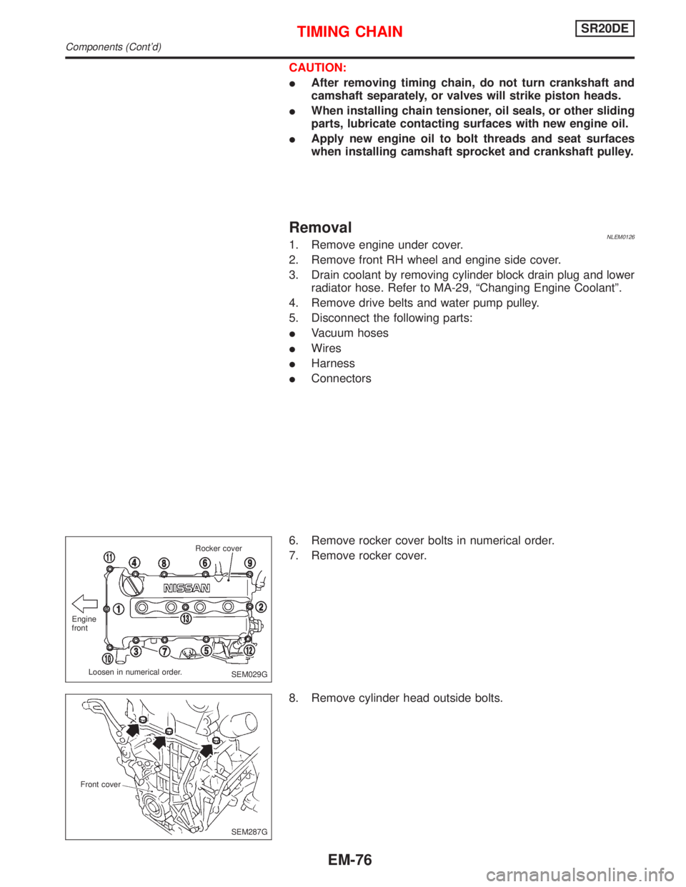
6. Remove rocker cover bolts in numerical order.
7. Remove rocker cover.
8. Remove cylinder head outside bolts.
SEM029G Engine
front
Loosen in numerical order.Rocker cover
SEM287G Front cover
TIMING CHAINSR20DE
Components (Cont'd)
EM-76
Page 1623 of 2267
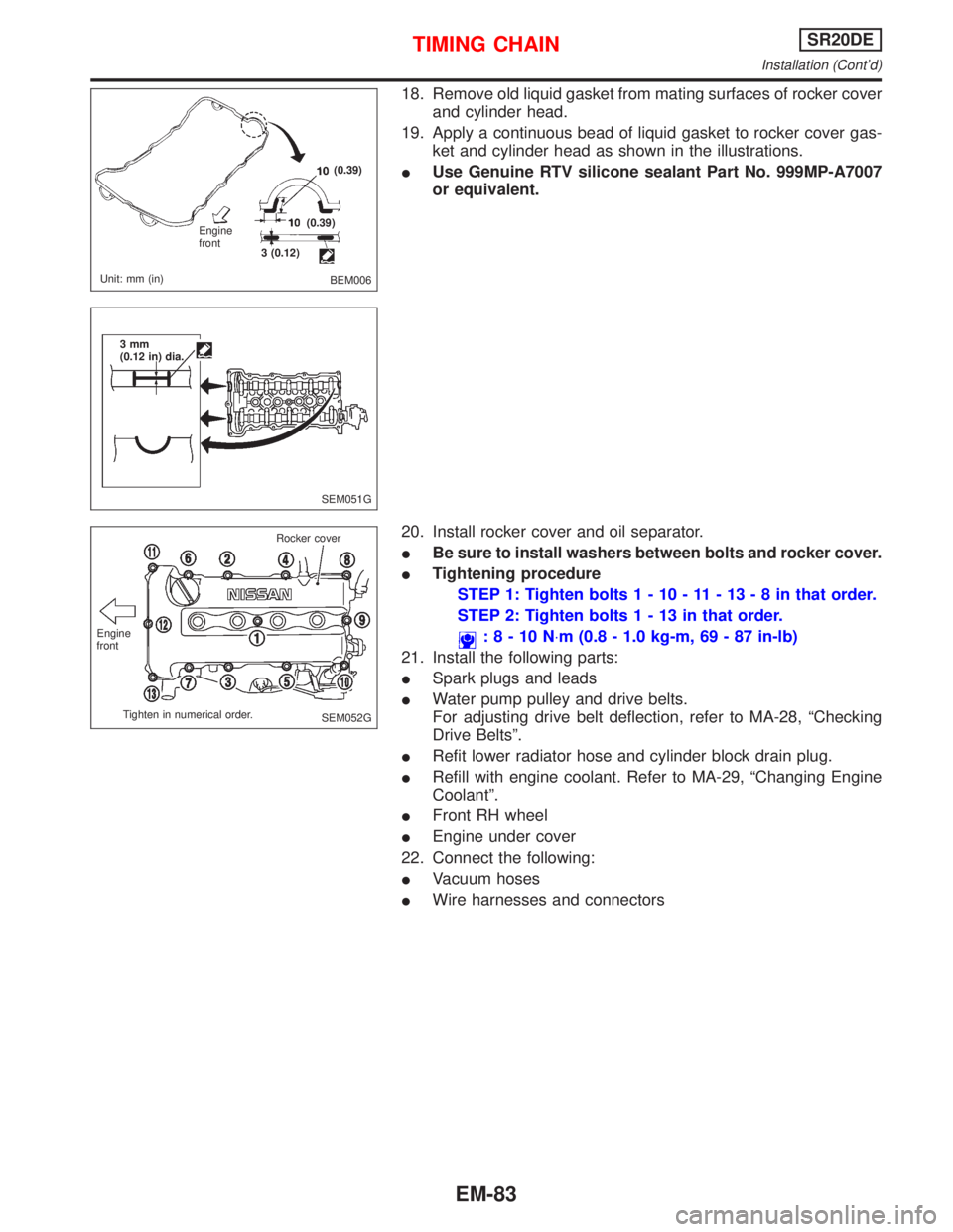
18. Remove old liquid gasket from mating surfaces of rocker cover
and cylinder head.
19. Apply a continuous bead of liquid gasket to rocker cover gas-
ket and cylinder head as shown in the illustrations.
IUse Genuine RTV silicone sealant Part No. 999MP-A7007
or equivalent.
20. Install rocker cover and oil separator.
IBe sure to install washers between bolts and rocker cover.
ITightening procedure
STEP 1: Tighten bolts1-10-11-13-8inthat order.
STEP 2: Tighten bolts1-13inthat order.
:8-10N×m (0.8 - 1.0 kg-m, 69 - 87 in-lb)
21. Install the following parts:
ISpark plugs and leads
IWater pump pulley and drive belts.
For adjusting drive belt deflection, refer to MA-28, ªChecking
Drive Beltsº.
IRefit lower radiator hose and cylinder block drain plug.
IRefill with engine coolant. Refer to MA-29, ªChanging Engine
Coolantº.
IFront RH wheel
IEngine under cover
22. Connect the following:
IVacuum hoses
IWire harnesses and connectors
BEM006 Engine
front
Unit: mm (in)3 (0.12)(0.39)
(0.39)
SEM051G 3mm
(0.12 in) dia.
SEM052G Engine
front
Tighten in numerical order.Rocker cover
TIMING CHAINSR20DE
Installation (Cont'd)
EM-83
Page 1624 of 2267
VALVE OIL SEAL
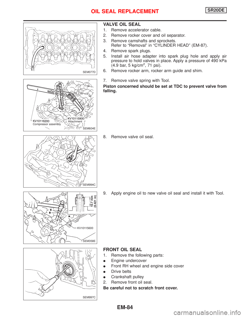
1. Remove accelerator cable.
2. Remove rocker cover and oil separator.
3. Remove camshafts and sprockets.
Refer to ªRemovalº in ªCYLINDER HEADº (EM-87).
4. Remove spark plugs.
5. Install air hose adapter into spark plug hole and apply air
pressure to hold valves in place. Apply a pressure of 490 kPa
(4.9 bar, 5 kg/cm
2, 71 psi).
6. Remove rocker arm, rocker arm guide and shim.
7. Remove valve spring with Tool.
Piston concerned should be set at TDC to prevent valve from
falling.
8. Remove valve oil seal.
9. Apply engine oil to new valve oil seal and install it with Tool.
FRONT OIL SEAL
1. Remove the following parts:
IEngine undercover
IFront RH wheel and engine side cover
IDrive belts
ICrankshaft pulley
2. Remove front oil seal.
Be careful not to scratch front cover.
SEM077D
SEM604E Compressor assemblyAttachment
SEM994C
SEM358E
10.7 mm
(0.421 in)
KV10115600
SEM997C
OIL SEAL REPLACEMENTSR20DE
EM-84
Page 1647 of 2267
WARNING:
IPosition vehicle on a flat and solid surface.
IPlace chocks at front and back of rear wheels.
IDo not remove engine until exhaust system has com-
pletely cooled;
Otherwise, you may burn yourself and/or fire may break
out in fuel line.
IBefore disconnecting fuel hose, release fuel pressure
from fuel line.
Refer to ªReleasing Fuel Pressureº in EC section.
IBe sure to hoist engine and transaxle in a safe manner.
IFor engines not equipped with engine slingers, attach
slingers and bolts described in PARTS CATALOG.
CAUTION:
IWhen lifting engine, be sure to clear surrounding parts.
Use special care for accelerator cable, brake lines and
brake master cylinder.
IIn hoisting the engine, always use engine slingers in a
safe manner.
IWhen removing drive shaft, be careful not to damage
grease seal of transaxle.
Removal
1. Remove engine under cover and hood.
2. Drain coolant from both cylinder block, and radiator.
3. Drain engine oil.
4. Remove vacuum hoses, fuel hoses, wires, harness and con-
nectors.
5. Remove exhaust tubes, ball joints and drive shafts.
6. Remove radiator and fans.
7. Remove drive belts.
8. Remove alternator, compressor and power steering oil pump
from engine.
9. Set a suitable transmission jack under transaxle. Hoist engine
with engine slinger.
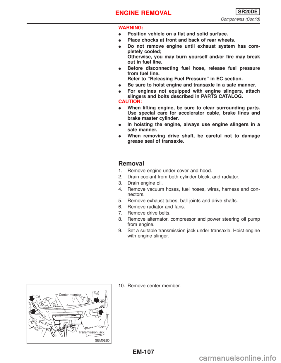
10. Remove center member.
SEM092D Center member
Transmission jack
ENGINE REMOVALSR20DE
Components (Cont'd)
EM-107
Page 1661 of 2267
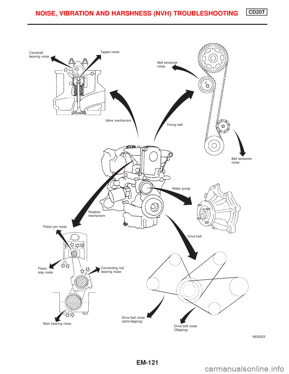
NEM333 Camshaft
bearing noiseTappet noise
Belt tensioner
noise
Valve mechanism
Piston pin noiseTiming belt
Water pump
Rotation
mechanism
Drive belt
Connecting rod
bearing noise Piston
slap noise
Main bearing noiseDrive belt noise
(stick/slipping)
Belt tensioner
noise
Drive belt noise
(Slipping)
NOISE, VIBRATION AND HARSHNESS (NVH) TROUBLESHOOTINGCD20T
EM-121
Page 1662 of 2267
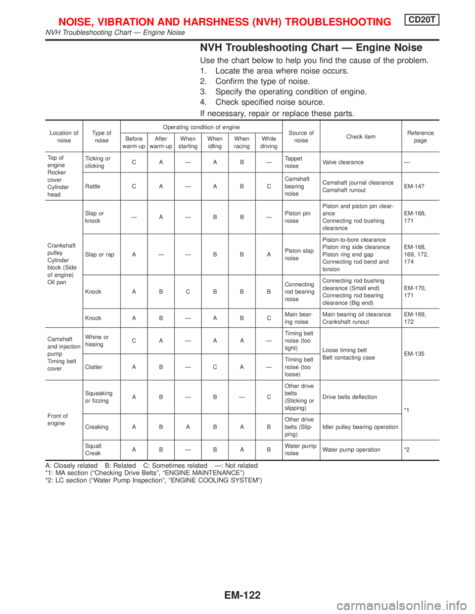
NVH Troubleshooting Chart Ð Engine Noise
Use the chart below to help you find the cause of the problem.
1. Locate the area where noise occurs.
2. Confirm the type of noise.
3. Specify the operating condition of engine.
4. Check specified noise source.
If necessary, repair or replace these parts.
Location of
noiseType of
noiseOperating condition of engine
Source of
noiseCheck itemReference
page Before
warm-upAfter
warm-upWhen
startingWhen
idlingWhen
racingWhile
driving
To p o f
engine
Rocker
cover
Cylinder
headTicking or
clickingCAÐABÐTappet
noiseValve clearance Ð
Rattle C A Ð A B CCamshaft
bearing
noiseCamshaft journal clearance
Camshaft runoutEM-147
Crankshaft
pulley
Cylinder
block (Side
of engine)
Oil panSlap or
knockÐAÐB BÐPiston pin
noisePiston and piston pin clear-
ance
Connecting rod bushing
clearanceEM-168,
171
Slap or rap A Ð Ð B B APiston slap
noisePiston-to-bore clearance
Piston ring side clearance
Piston ring end gap
Connecting rod bend and
torsionEM-168,
169, 172,
174
Knock A B C B B BConnecting
rod bearing
noiseConnecting rod bushing
clearance (Small end)
Connecting rod bearing
clearance (Big end)EM-170,
171
Knock A B Ð A B CMain bear-
ing noiseMain bearing oil clearance
Crankshaft runoutEM-169,
172
Camshaft
and injection
pump
Timing belt
coverWhine or
hissingCAÐAAÐTiming belt
noise (too
tight)
Loose timing belt
Belt contacting caseEM-135
Clatter A B Ð C A ÐTiming belt
noise (too
loose)
Front of
engineSqueaking
or fizzingABÐBÐCOther drive
belts
(Sticking or
slipping)Drive belts deflection
*1
CreakingABABABOther drive
belts (Slip-
ping)Idler pulley bearing operation
Squall
CreakABÐBABWater pump
noiseWater pump operation *2
A: Closely related B: Related C: Sometimes related Ð: Not related
*1: MA section (ªChecking Drive Beltsº, ªENGINE MAINTENANCEº)
*2: LC section (ªWater Pump Inspectionº, ªENGINE COOLING SYSTEMº)
NOISE, VIBRATION AND HARSHNESS (NVH) TROUBLESHOOTINGCD20T
NVH Troubleshooting Chart Ð Engine Noise
EM-122
Page 1663 of 2267
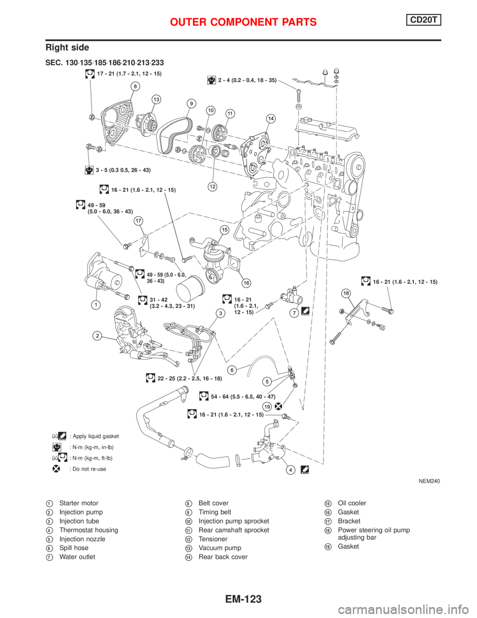
Right side
p1Starter motor
p2Injection pump
p3Injection tube
p4Thermostat housing
p5Injection nozzle
p6Spill hose
p7Water outlet
p8Belt cover
p9Timing belt
p10Injection pump sprocket
p11Rear camshaft sprocket
p12Tensioner
p13Vacuum pump
p14Rear back cover
p15Oil cooler
p16Gasket
p17Bracket
p18Power steering oil pump
adjusting bar
p19Gasket
NEM240
17 - 21 (1.7 - 2.1, 12 - 15)2 - 4 (0.2 - 0.4, 18 - 35)
3 - 5 (0.3 0.5, 26 - 43)
49-59
(5.0 - 6.0, 36 - 43)
49 - 59 (5.0 - 6.0,
36 - 43)
31-42
(3.2 - 4.3, 23 - 31)16-21
(1.6 - 2.1,
12 - 15)
16 - 21 (1.6 - 2.1, 12 - 15)
54 - 64 (5.5 - 6.5, 40 - 47)
22 - 25 (2.2 - 2.5, 16 - 18)
16 - 21 (1.6 - 2.1, 12 - 15)
SEC. 130×135×185×186×210×213×233
îî: Apply liquid gasket
: N´m (kg-m, in-lb)
îî
: N´m (kg-m, ft-lb)
: Do not re-use
16 - 21 (1.6 - 2.1, 12 - 15)
OUTER COMPONENT PARTSCD20T
EM-123