Page 1552 of 2267
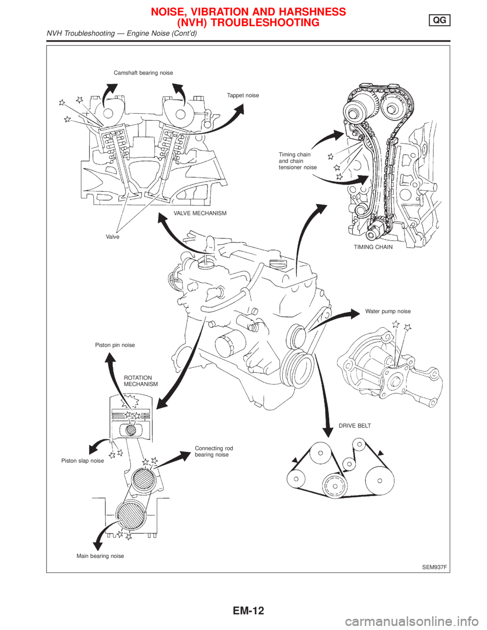
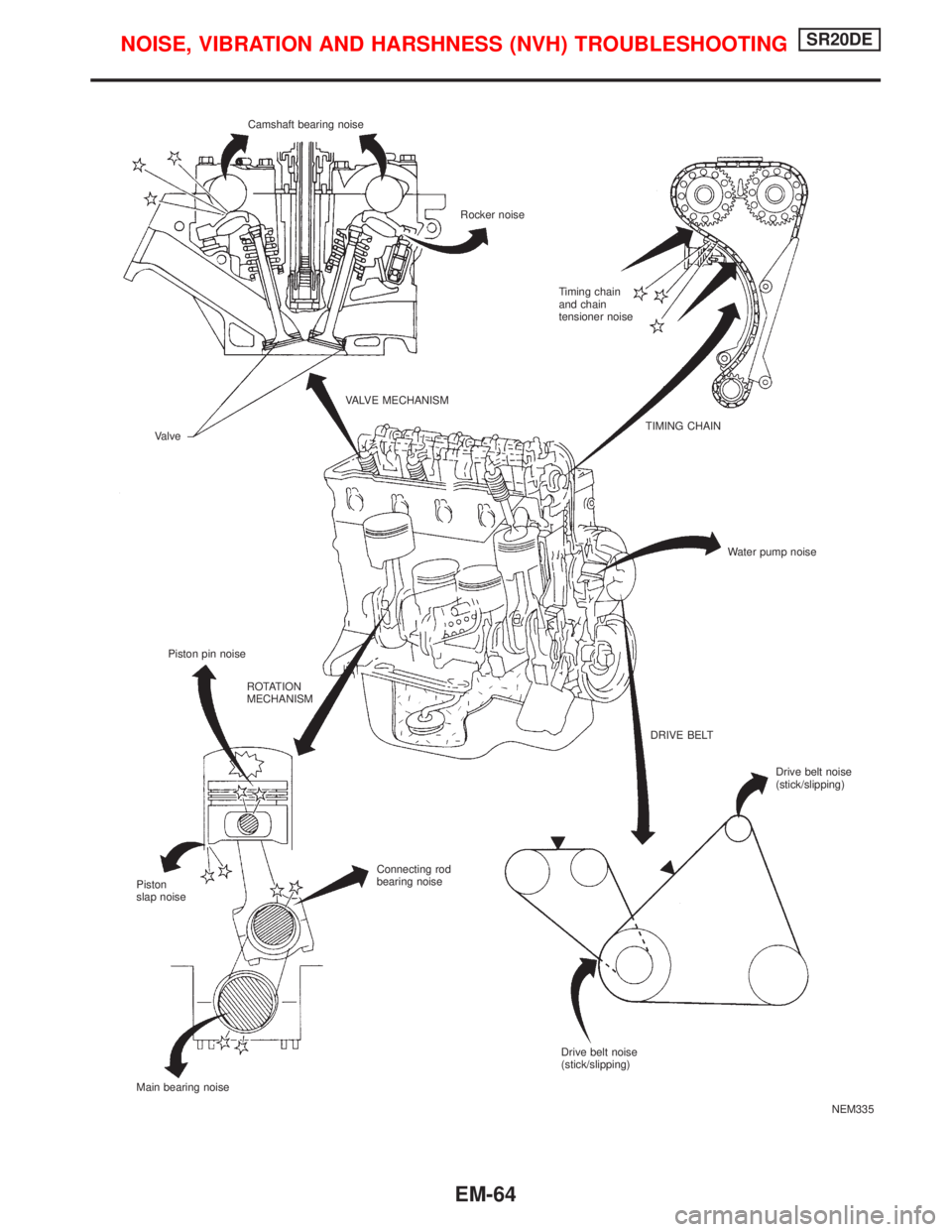
SEM937F Camshaft bearing noise
Tappet noise
Timing chain
and chain
tensioner noise
VALVE MECHANISM
Valve
Piston pin noiseTIMING CHAIN
Water pump noise
ROTATION
MECHANISM
DRIVE BELT
Connecting rod
bearing noise
Piston slap noise
Main bearing noise
NOISE, VIBRATION AND HARSHNESS
(NVH) TROUBLESHOOTINGQG
NVH Troubleshooting Ð Engine Noise (Cont'd)
EM-12
Page 1560 of 2267
CAUTION:
IAfter removing timing chain, do not turn crankshaft and
camshaft separately, or valves will strike piston heads.
IWhen installing chain tensioner, oil seals, or other sliding
parts, lubricate contacting surfaces with new engine oil.
IApply new engine oil to bolt threads and seat surfaces
when installing camshaft sprocket and crankshaft pulley.
IWhen removing oil pump assembly, remove camshaft
position sensor (PHASE), then remove timing chain from
engine.
IBe careful not to damage sensor edges.
RemovalNCEM00121. Drain engine coolant from radiator and cylinder block.
Be careful not to spill coolant on drive belts.
2. Release fuel pressure.
Refer to EC section (ªFuel Pressure Releaseº, ªBASIC SER-
VICE PROCEDUREº).
3. Remove the following belts.
IPower steering pump drive belt
IAlternator drive belt
4. Remove power steering pulley and pump with bracket.
5. Remove front right-side wheel.
6. Remove front right-side splash cover.
7. Remove front undercovers.
8. Remove front exhaust tube.
9. Remove vacuum hoses, fuel hoses, and so on.
10. Remove ignition coils.
11. Remove cylinder head front mounting bracket.
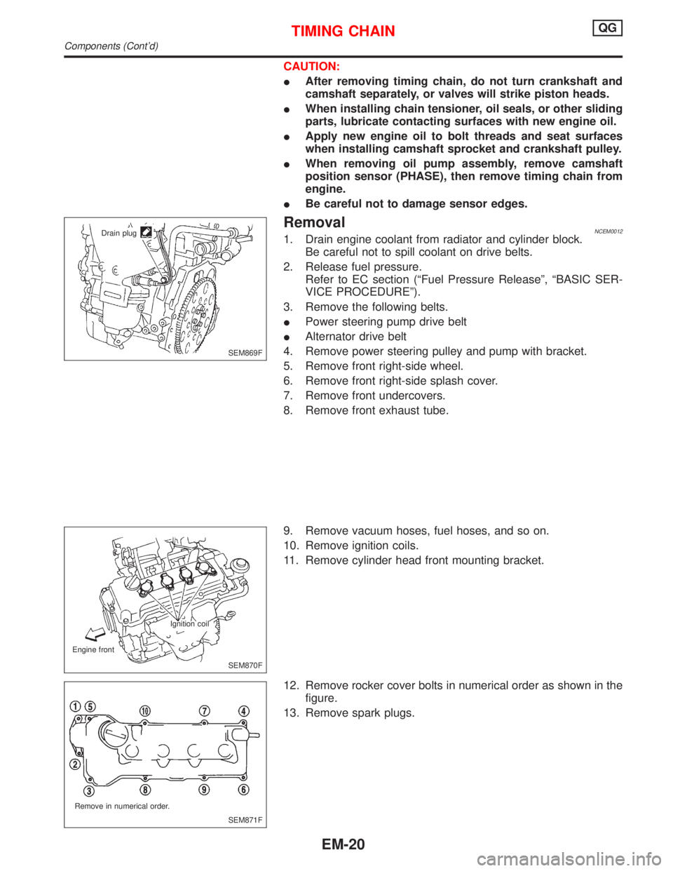
12. Remove rocker cover bolts in numerical order as shown in the
figure.
13. Remove spark plugs.
SEM869F Drain plug
SEM870F Ignition coil
Engine front
SEM871F Remove in numerical order.
TIMING CHAINQG
Components (Cont'd)
EM-20
Page 1568 of 2267
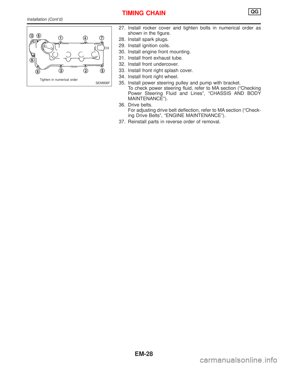
27. Install rocker cover and tighten bolts in numerical order as
shown in the figure.
28. Install spark plugs.
29. Install ignition coils.
30. Install engine front mounting.
31. Install front exhaust tube.
32. Install front undercover.
33. Install front right splash cover.
34. Install front right wheel.
35. Install power steering pulley and pump with bracket.
To check power steering fluid, refer to MA section (ªChecking
Power Steering Fluid and Linesº, ªCHASSIS AND BODY
MAINTENANCEº).
36. Drive belts.
For adjusting drive belt deflection, refer to MA section (ªCheck-
ing Drive Beltsº, ªENGINE MAINTENANCEº).
37. Reinstall parts in reverse order of removal.
SEM908F Tighten in numerical order
TIMING CHAINQG
Installation (Cont'd)
EM-28
Page 1569 of 2267
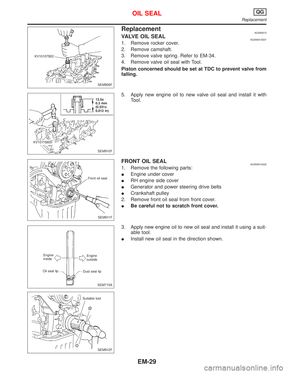
ReplacementNCEM0015VALVE OIL SEALNCEM0015S011. Remove rocker cover.
2. Remove camshaft.
3. Remove valve spring. Refer to EM-34.
4. Remove valve oil seal with Tool.
Piston concerned should be set at TDC to prevent valve from
falling.
5. Apply new engine oil to new valve oil seal and install it with
Tool.
FRONT OIL SEALNCEM0015S021. Remove the following parts:
IEngine under cover
IRH engine side cover
IGenerator and power steering drive belts
ICrankshaft pulley
2. Remove front oil seal from front cover.
IBe careful not to scratch front cover.
3. Apply new engine oil to new oil seal and install it using a suit-
able tool.
IInstall new oil seal in the direction shown.
SEM909F KV10107902
SEM910F 13.5
0.3 mm
(0.531
0.012 in)
KV10115600
SEM911F Front oil seal
SEM715A Engine
outside
Dust seal lip Engine
inside
Oil seal lip
SEM912F Suitable tool
OIL SEALQG
Replacement
EM-29
Page 1572 of 2267
CAUTION:
IWhen installing camshaft and oil seal, lubricate contacting
surfaces with new engine oil.
IWhen tightening cylinder head bolts, camshaft sprocket
bolts and camshaft bracket bolts, lubricate bolt threads
and seat surfaces with new engine oil.
IAttach tags to valve lifters so as not to mix them up.
RemovalNCEM00171. Drain engine coolant from radiator and cylinder block.
Be careful not to spill coolant on drive belts.
2. Release fuel pressure.
Refer to EC section (ªFuel Pressure Releaseº, ªBASIC SER-
VICE PROCEDUREº).
3. Remove air duct to intake manifold collector.
4. Remove front undercovers.
5. Remove front exhaust tube.
6. Remove vacuum hoses, fuel hoses, water hoses, wires,
harness, connectors and so on.
7. Remove ignition coils.
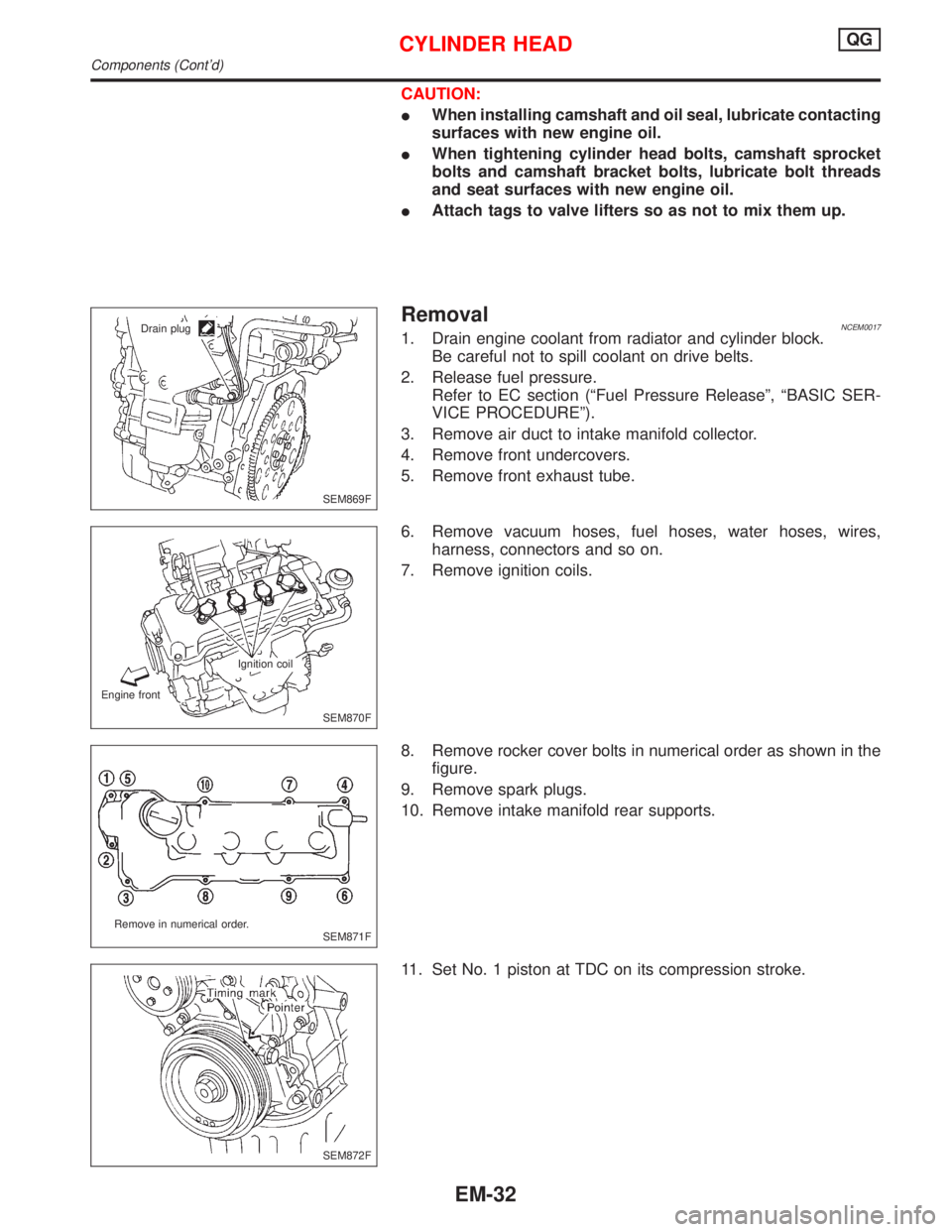
8. Remove rocker cover bolts in numerical order as shown in the
figure.
9. Remove spark plugs.
10. Remove intake manifold rear supports.
11. Set No. 1 piston at TDC on its compression stroke.
SEM869F Drain plug
SEM870F Ignition coil
Engine front
SEM871F Remove in numerical order.
SEM872F
CYLINDER HEADQG
Components (Cont'd)
EM-32
Page 1587 of 2267
Power Steering Fluid and Linesº, ªCHASSIS AND BODY
MAINTENANCEº).
21. Drive belts.
For adjusting drive belt deflection, refer to MA section (ªCheck-
ing Drive Beltsº, ªENGINE MAINTENANCEº).
22. Reinstall parts in reverse order of removal.
CYLINDER HEADQG
Installation (Cont'd)
EM-47
Page 1589 of 2267
WARNING:
IPosition vehicle on a flat and solid surface.
IPlace chocks at front and back of rear wheels.
IDo not remove engine until exhaust system has com-
pletely cooled off, otherwise, you may burn yourself
and/or fire may break out in fuel line.
IBefore disconnecting fuel hose, release pressure.
Refer to EC section (ªFuel Pressure Releaseº, ªBASIC
SERVICE PROCEDUREº).
IBe sure to lift engine and transaxle in a safe manner.
IFor engines not equipped with engine slingers, attach
proper slingers and bolts described in PARTS CATALOG.
CAUTION:
IWhen lifting engine, be sure to clear surrounding parts.
Use special care near accelerator wire casing, brake lines
and brake master cylinder.
IWhen lifting the engine, always use engine slingers in a
safe manner.
IWhen removing drive shaft, be careful not to damage
grease seal of transaxle.
IBefore separating engine and transaxle, remove crank-
shaft position sensor (POS) from the cylinder block
assembly.
IAlways be extra careful not to damage edge of crankshaft
position sensor (POS), or signal plate teeth.
Engine cannot be removed separately from transaxle. Remove
engine with transaxle as an assembly.
REMOVALNCEM0022S011. Drain coolant from radiator and cylinder block. Refer to (LC)
section (ªChanging Engine Coolantº, ªENGINE MAINTE-
NANCEº).
2. Drain engine oil.
3. Remove battery.
4. Remove coolant reservoir tank and bracket.
5. Remove drive belts.
6. Remove generator and air conditioner compressor from
engine.
7. Remove power steering oil pump from engine and position
aside.
Power steering oil pump does not need to be disconnected
from power steering tubes.
ENGINE REMOVALQG
Removal and Installation (Cont'd)
EM-49
Page 1604 of 2267
NEM335 Camshaft bearing noise
Rocker noise
Timing chain
and chain
tensioner noise
VALVE MECHANISM
Valve
Piston pin noiseTIMING CHAIN
Water pump noise
ROTATION
MECHANISM
DRIVE BELT
Connecting rod
bearing noise
Piston
slap noise
Main bearing noiseDrive belt noise
(stick/slipping)
Drive belt noise
(stick/slipping)
NOISE, VIBRATION AND HARSHNESS (NVH) TROUBLESHOOTINGSR20DE
EM-64