1999 NISSAN PRIMERA belt
[x] Cancel search: beltPage 318 of 2267
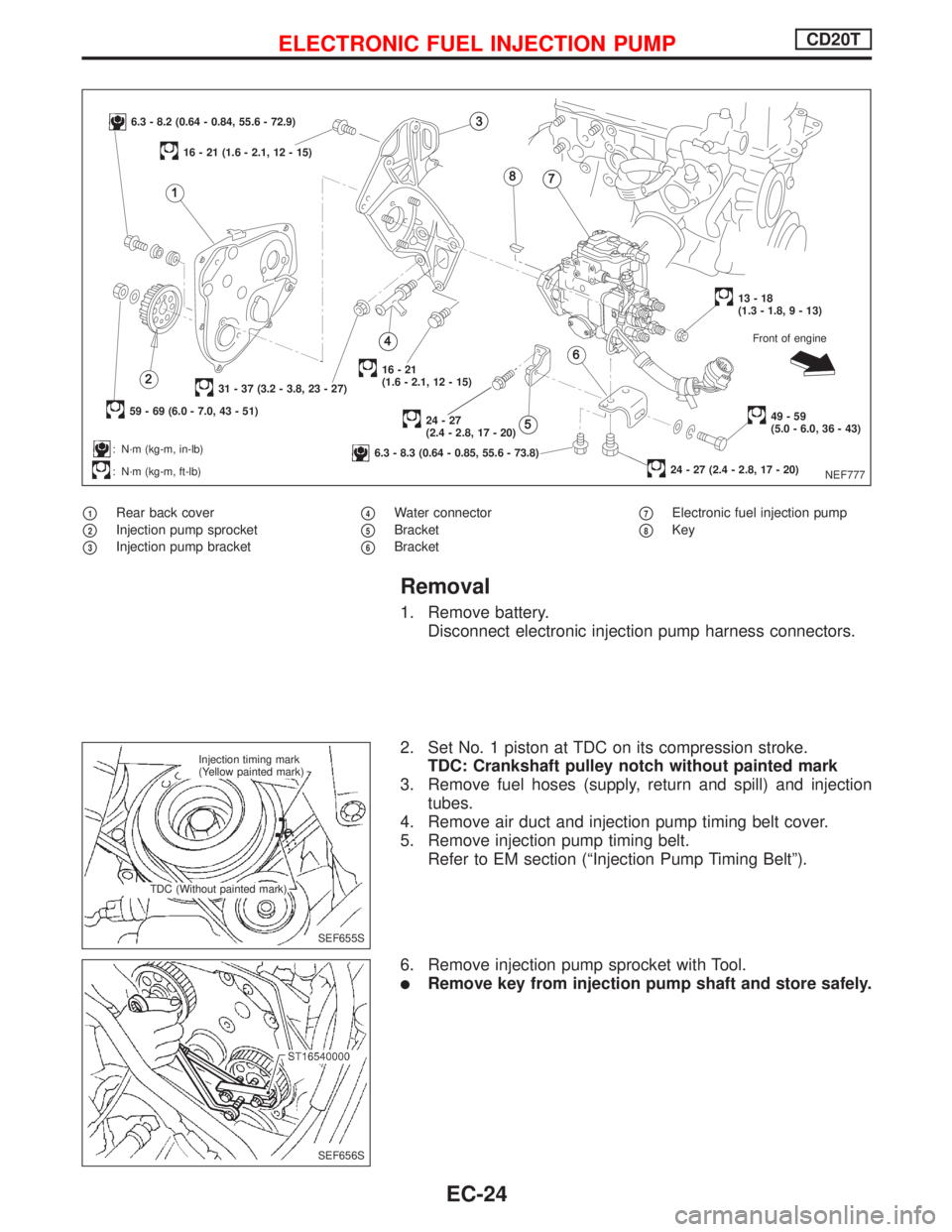
p1Rear back cover
p2Injection pump sprocket
p3Injection pump bracket
p4Water connector
p5Bracket
p6Bracket
p7Electronic fuel injection pump
p8Key
Removal
1. Remove battery.
Disconnect electronic injection pump harness connectors.
2. Set No. 1 piston at TDC on its compression stroke.
TDC: Crankshaft pulley notch without painted mark
3. Remove fuel hoses (supply, return and spill) and injection
tubes.
4. Remove air duct and injection pump timing belt cover.
5. Remove injection pump timing belt.
Refer to EM section (ªInjection Pump Timing Beltº).
6. Remove injection pump sprocket with Tool.
lRemove key from injection pump shaft and store safely.
NEF777
6.3 - 8.2 (0.64 - 0.84, 55.6 - 72.9)
59 - 69 (6.0 - 7.0, 43 - 51)
31 - 37 (3.2 - 3.8, 23 - 27)
: N´m (kg-m, in-lb)
: N´m (kg-m, ft-lb)
16 - 21 (1.6 - 2.1, 12 - 15)
16-21
(1.6 - 2.1, 12 - 15)
24-27
(2.4 - 2.8, 17 - 20)
6.3 - 8.3 (0.64 - 0.85, 55.6 - 73.8)
13-18
(1.3 - 1.8, 9 - 13)
49-59
(5.0 - 6.0, 36 - 43)
24 - 27 (2.4 - 2.8, 17 - 20)Front of engine
SEF655S Injection timing mark
(Yellow painted mark)
TDC (Without painted mark)
SEF656S
ELECTRONIC FUEL INJECTION PUMPCD20T
EC-24
Page 319 of 2267
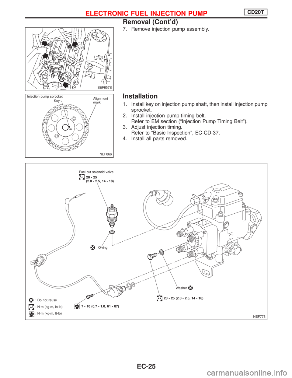
7. Remove injection pump assembly.
Installation
1. Install key on injection pump shaft, then install injection pump
sprocket.
2. Install injection pump timing belt.
Refer to EM section (ªInjection Pump Timing Beltº).
3. Adjust injection timing.
Refer to ªBasic Inspectionº, EC-CD-37.
4. Install all parts removed.
SEF657S
NEF866 Injection pump sprocket
KeyAlignment
mark
NEF778 Fuel cut solenoid valve
20-25
(2.0 - 2.5, 14 - 18)
O-ring
7 - 10 (0.7 - 1.0, 61 - 87)
20 - 25 (2.0 - 2.5, 14 - 18)Washer: Do not reuse
: N´m (kg-m, in-lb)
: N´m (kg-m, ft-lb)
ELECTRONIC FUEL INJECTION PUMPCD20T
Removal (Cont'd)
EC-25
Page 336 of 2267
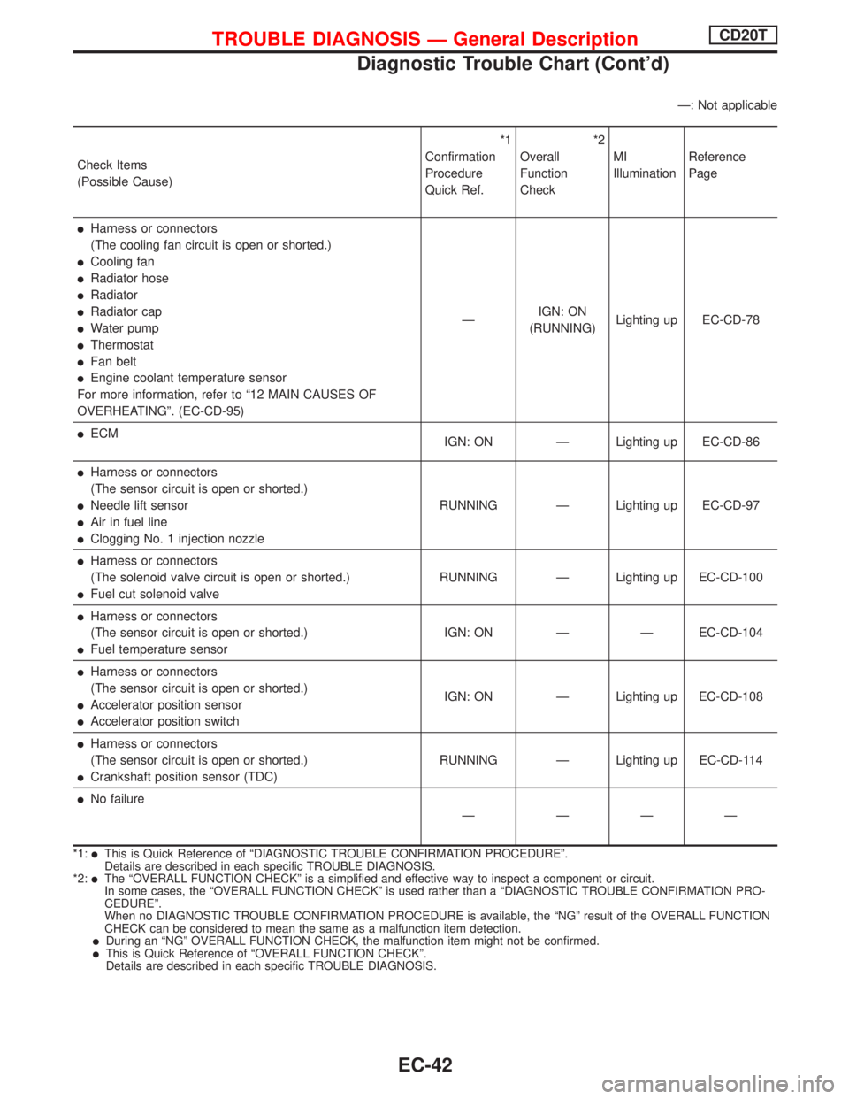
Ð: Not applicable
Check Items
(Possible Cause)*1
Confirmation
Procedure
Quick Ref.*2
Overall
Function
CheckMI
IlluminationReference
Page
lHarness or connectors
(The cooling fan circuit is open or shorted.)
lCooling fan
lRadiator hose
lRadiator
lRadiator cap
lWater pump
lThermostat
lFan belt
lEngine coolant temperature sensor
For more information, refer to ª12 MAIN CAUSES OF
OVERHEATINGº. (EC-CD-95)ÐIGN: ON
(RUNNING)Lighting up EC-CD-78
lECM
IGN: ON Ð Lighting up EC-CD-86
lHarness or connectors
(The sensor circuit is open or shorted.)
lNeedle lift sensor
lAir in fuel line
lClogging No. 1 injection nozzleRUNNING Ð Lighting up EC-CD-97
lHarness or connectors
(The solenoid valve circuit is open or shorted.)
lFuel cut solenoid valveRUNNING Ð Lighting up EC-CD-100
lHarness or connectors
(The sensor circuit is open or shorted.)
lFuel temperature sensorIGN: ON Ð Ð EC-CD-104
lHarness or connectors
(The sensor circuit is open or shorted.)
lAccelerator position sensor
lAccelerator position switchIGN: ON Ð Lighting up EC-CD-108
lHarness or connectors
(The sensor circuit is open or shorted.)
lCrankshaft position sensor (TDC)RUNNING Ð Lighting up EC-CD-114
lNo failure
Ð ÐÐÐ
*1:lThis is Quick Reference of ªDIAGNOSTIC TROUBLE CONFIRMATION PROCEDUREº.
Details are described in each specific TROUBLE DIAGNOSIS.
*2:
lThe ªOVERALL FUNCTION CHECKº is a simplified and effective way to inspect a component or circuit.
In some cases, the ªOVERALL FUNCTION CHECKº is used rather than a ªDIAGNOSTIC TROUBLE CONFIRMATION PRO-
CEDUREº.
When no DIAGNOSTIC TROUBLE CONFIRMATION PROCEDURE is available, the ªNGº result of the OVERALL FUNCTION
CHECK can be considered to mean the same as a malfunction item detection.
lDuring an ªNGº OVERALL FUNCTION CHECK, the malfunction item might not be confirmed.lThis is Quick Reference of ªOVERALL FUNCTION CHECKº.
Details are described in each specific TROUBLE DIAGNOSIS.
TROUBLE DIAGNOSIS Ð General DescriptionCD20T
Diagnostic Trouble Chart (Cont'd)
EC-42
Page 381 of 2267
Cooling Fan (Overheat)
SYSTEM DESCRIPTION
Vehicle speed sensorEVehicle speed
ECM
ECooling
fan
relay(s)Engine coolant temperature sensorEEngine coolant temperature
Air conditioner switch
EAir conditioner ªONº signal
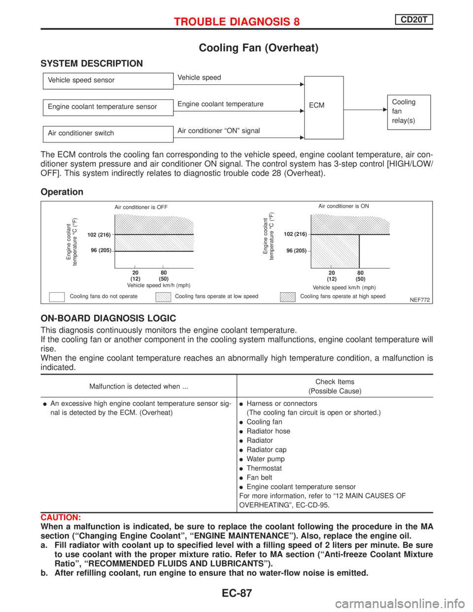
The ECM controls the cooling fan corresponding to the vehicle speed, engine coolant temperature, air con-
ditioner system pressure and air conditioner ON signal. The control system has 3-step control [HIGH/LOW/
OFF]. This system indirectly relates to diagnostic trouble code 28 (Overheat).
Operation
ON-BOARD DIAGNOSIS LOGIC
This diagnosis continuously monitors the engine coolant temperature.
If the cooling fan or another component in the cooling system malfunctions, engine coolant temperature will
rise.
When the engine coolant temperature reaches an abnormally high temperature condition, a malfunction is
indicated.
Malfunction is detected when ...Check Items
(Possible Cause)
lAn excessive high engine coolant temperature sensor sig-
nal is detected by the ECM. (Overheat)lHarness or connectors
(The cooling fan circuit is open or shorted.)
lCooling fan
lRadiator hose
lRadiator
lRadiator cap
lWater pump
lThermostat
lFan belt
lEngine coolant temperature sensor
For more information, refer to ª12 MAIN CAUSES OF
OVERHEATINGº, EC-CD-95.
CAUTION:
When a malfunction is indicated, be sure to replace the coolant following the procedure in the MA
section (ªChanging Engine Coolantº, ªENGINE MAINTENANCEº). Also, replace the engine oil.
a. Fill radiator with coolant up to specified level with a filling speed of 2 liters per minute. Be sure
to use coolant with the proper mixture ratio. Refer to MA section (ªAnti-freeze Coolant Mixture
Ratioº, ªRECOMMENDED FLUIDS AND LUBRICANTSº).
b. After refilling coolant, run engine to ensure that no water-flow noise is emitted.
NEF772
Engine coolant
temperature ÉC (ÉF)
Air conditioner is OFF
.102 (216)
.96 (205)
.20
(12).80
(50)
Vehicle speed km/h (mph)
Cooling fans do not operateCooling fans operate at high speed
Engine coolant
temperature ÉC (ÉF)
Vehicle speed km/h (mph)
.20
(12).80
(50)
.102 (216)
.96 (205)Air conditioner is ON
Cooling fans operate at low speed
TROUBLE DIAGNOSIS 8CD20T
EC-87
Page 443 of 2267
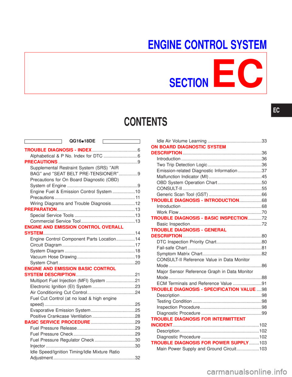
ENGINE CONTROL SYSTEM
SECTION
EC
CONTENTS
QG16I18DE
TROUBLE DIAGNOSIS - INDEX....................................6
Alphabetical & P No. Index for DTC ...........................6
PRECAUTIONS...............................................................9
Supplemental Restraint System (SRS)²AIR
BAG²and²SEAT BELT PRE-TENSIONER²...............9
Precautions for On Board Diagnostic (OBD)
System of Engine ........................................................9
Engine Fuel & Emission Control System ..................10
Precautions ................................................................ 11
Wiring Diagrams and Trouble Diagnosis ...................12
PREPARATION..............................................................13
Special Service Tools ................................................13
Commercial Service Tool ...........................................13
ENGINE AND EMISSION CONTROL OVERALL
SYSTEM.........................................................................14
Engine Control Component Parts Location ...............14
Circuit Diagram ..........................................................17
System Diagram ........................................................18
Vacuum Hose Drawing ..............................................19
System Chart .............................................................20
ENGINE AND EMISSION BASIC CONTROL
SYSTEM DESCRIPTION...............................................21
Multiport Fuel Injection (MFI) System .......................21
Electronic Ignition (EI) System ..................................23
Air Conditioning Cut Control ......................................24
Fuel Cut Control (at no load & high engine
speed) ........................................................................25
Evaporative Emission System ...................................25
Positive Crankcase Ventilation ..................................28
BASIC SERVICE PROCEDURE...................................29
Fuel Pressure Release ..............................................29
Fuel Pressure Check .................................................29
Fuel Pressure Regulator Check ................................30
Injector .......................................................................30
Idle Speed/Ignition Timing/Idle Mixture Ratio
Adjustment .................................................................32Idle Air Volume Learning ...........................................33
ON BOARD DIAGNOSTIC SYSTEM
DESCRIPTION...............................................................36
Introduction ................................................................36
Two Trip Detection Logic ...........................................36
Emission-related Diagnostic Information ...................37
Malfunction Indicator (MI) ..........................................45
OBD System Operation Chart ...................................50
CONSULT-II ...............................................................55
Generic Scan Tool (GST) ..........................................66
TROUBLE DIAGNOSIS - INTRODUCTION..................68
Introduction ................................................................68
Work Flow ..................................................................70
TROUBLE DIAGNOSIS - BASIC INSPECTION...........72
Basic Inspection.........................................................72
TROUBLE DIAGNOSIS - GENERAL
DESCRIPTION...............................................................80
DTC Inspection Priority Chart....................................80
Fail-safe Chart ...........................................................81
Symptom Matrix Chart ...............................................82
CONSULT-II Reference Value in Data Monitor
Mode ..........................................................................86
Major Sensor Reference Graph in Data Monitor
Mode ..........................................................................88
ECM Terminals and Reference Value .......................91
TROUBLE DIAGNOSIS - SPECIFICATION VALUE....98
Description .................................................................98
Testing Condition .......................................................98
Inspection Procedure .................................................98
Diagnostic Procedure ................................................99
TROUBLE DIAGNOSIS FOR INTERMITTENT
INCIDENT.....................................................................102
Description ...............................................................102
Diagnostic Procedure ..............................................102
TROUBLE DIAGNOSIS FOR POWER SUPPLY........103
Main Power Supply and Ground Circuit ..................103
EC
Page 451 of 2267
Supplemental Restraint System (SRS) ªAIR
BAGº and ªSEAT BELT PRE-TENSIONERº
NCEC0002The Supplemental Restraint System ªAIR BAGº and ªSEAT BELT PRE-TENSIONERº, used along with a seat
belt, help to reduce the risk or severity of injury to the driver and front passenger in a frontal collision. The
Supplemental Restraint System consists of air bag modules (located in the center of the steering wheel and
on the instrument panel on the passenger side), seat belt pre-tensioners, a diagnosis sensor unit, warning
lamp, wiring harness and spiral cable.
In addition to the supplemental air bag modules for a frontal collision, the supplemental side air bag used along
with the seat belt helps to reduce the risk or severity of injury to the driver and front passenger in a side col-
lision. The supplemental side air bag consists of air bag modules (located in the outer side of front seats),
satellite sensor, diagnosis sensor unit (one of components of supplemental air bags for a frontal collision),
wiring harness, warning lamp (one of components of supplemental air bags for a frontal collision). Information
necessary to service the system safely is included in theRS sectionof this Service Manual.
WARNING:
ITo avoid rendering the SRS inoperative, which could increase the risk of personal injury or death
in the event of a collision which would result in air bag inflation, all maintenance must be performed
by an authorized NISSAN dealer.
IImproper maintenance, including incorrect removal and installation of the SRS, can lead to per-
sonal injury caused by unintentional activation of the system.
IDo not use electrical test equipment on any circuit related to the SRS unless instructed to in this
Service Manual. SRS wiring harnesses (except ªSEAT BELT PRE-TENSIONERº connector) can be
identified with yellow harness connector (and with yellow harness protector or yellow insulation
tape before the harness connectors).
Precautions for On Board Diagnostic (OBD)
System of Engine
NCEC0003The ECM has an on board diagnostic system. It will light up the malfunction indicator (MI) to warn the driver
of a malfunction causing emission deterioration.
CAUTION:
IBe sure to turn the ignition switch ªOFFº and disconnect the negative battery terminal before any
repair or inspection work. The open/short circuit of related switches, sensors, solenoid valves, etc.
will cause the MI to light up.
IBe sure to connect and lock the connectors securely after work. A loose (unlocked) connector will
cause the MI to light up due to the open circuit. (Be sure the connector is free from water, grease,
dirt, bent terminals, etc.)
ICertain systems and components, especially those related to OBD, may use a new style slide-
locking type harness connector.
For description and how to disconnect, refer to EL section, ªDescriptionº, ªHARNESS CONNEC-
TORº.
IBe sure to route and secure the harnesses properly after work. The interference of the harness with
a bracket, etc. may cause the MI to light up due to the short circuit.
IBe sure to connect rubber tubes properly after work. A misconnected or disconnected rubber tube
may cause the MI to light up due to the malfunction of the EGR system or fuel injection system,
etc.
IBe sure to erase the unnecessary malfunction information (repairs completed) from the ECM before
returning the vehicle to the customer.
PRECAUTIONSQG16I18DE
Supplemental Restraint System (SRS) ªAIR BAGº and ªSEAT BELT PRE-TENSIONERº
EC-9
Page 801 of 2267
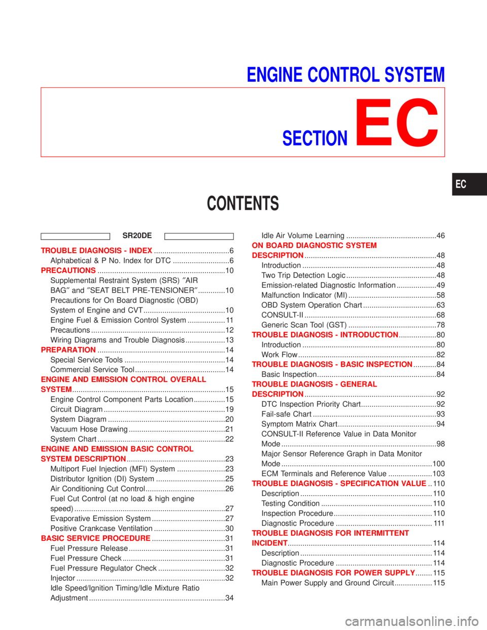
ENGINE CONTROL SYSTEM
SECTION
EC
CONTENTS
SR20DE
TROUBLE DIAGNOSIS - INDEX....................................6
Alphabetical & P No. Index for DTC ...........................6
PRECAUTIONS.............................................................10
Supplemental Restraint System (SRS)²AIR
BAG²and²SEAT BELT PRE-TENSIONER².............10
Precautions for On Board Diagnostic (OBD)
System of Engine and CVT .......................................10
Engine Fuel & Emission Control System .................. 11
Precautions ................................................................12
Wiring Diagrams and Trouble Diagnosis ...................13
PREPARATION.............................................................14
Special Service Tools ................................................14
Commercial Service Tool ...........................................14
ENGINE AND EMISSION CONTROL OVERALL
SYSTEM.........................................................................15
Engine Control Component Parts Location ...............15
Circuit Diagram ..........................................................19
System Diagram ........................................................20
Vacuum Hose Drawing ..............................................21
System Chart .............................................................22
ENGINE AND EMISSION BASIC CONTROL
SYSTEM DESCRIPTION...............................................23
Multiport Fuel Injection (MFI) System .......................23
Distributor Ignition (DI) System .................................25
Air Conditioning Cut Control ......................................26
Fuel Cut Control (at no load & high engine
speed) ........................................................................27
Evaporative Emission System ...................................27
Positive Crankcase Ventilation ..................................30
BASIC SERVICE PROCEDURE...................................31
Fuel Pressure Release ..............................................31
Fuel Pressure Check .................................................31
Fuel Pressure Regulator Check ................................32
Injector .......................................................................32
Idle Speed/Ignition Timing/Idle Mixture Ratio
Adjustment .................................................................34Idle Air Volume Learning ...........................................46
ON BOARD DIAGNOSTIC SYSTEM
DESCRIPTION...............................................................48
Introduction ................................................................48
Two Trip Detection Logic ...........................................48
Emission-related Diagnostic Information ...................49
Malfunction Indicator (MI) ..........................................58
OBD System Operation Chart ...................................63
CONSULT-II ...............................................................68
Generic Scan Tool (GST) ..........................................78
TROUBLE DIAGNOSIS - INTRODUCTION..................80
Introduction ................................................................80
Work Flow ..................................................................82
TROUBLE DIAGNOSIS - BASIC INSPECTION...........84
Basic Inspection.........................................................84
TROUBLE DIAGNOSIS - GENERAL
DESCRIPTION...............................................................92
DTC Inspection Priority Chart....................................92
Fail-safe Chart ...........................................................93
Symptom Matrix Chart ...............................................94
CONSULT-II Reference Value in Data Monitor
Mode ..........................................................................98
Major Sensor Reference Graph in Data Monitor
Mode ........................................................................100
ECM Terminals and Reference Value .....................103
TROUBLE DIAGNOSIS - SPECIFICATION VALUE.. 110
Description ............................................................... 110
Testing Condition ..................................................... 110
Inspection Procedure ............................................... 110
Diagnostic Procedure .............................................. 111
TROUBLE DIAGNOSIS FOR INTERMITTENT
INCIDENT..................................................................... 114
Description ............................................................... 114
Diagnostic Procedure .............................................. 114
TROUBLE DIAGNOSIS FOR POWER SUPPLY........ 115
Main Power Supply and Ground Circuit .................. 115
EC
Page 810 of 2267
Supplemental Restraint System (SRS) ªAIR
BAGº and ªSEAT BELT PRE-TENSIONERº
NCEC0002The Supplemental Restraint System ªAIR BAGº and ªSEAT BELT PRE-TENSIONERº, used along with a seat
belt, help to reduce the risk or severity of injury to the driver and front passenger in a frontal collision. The
Supplemental Restraint System consists of air bag modules (located in the center of the steering wheel and
on the instrument panel on the passenger side), seat belt pre-tensioners, a diagnosis sensor unit, warning
lamp, wiring harness and spiral cable.
In addition to the supplemental air bag modules for a frontal collision, the supplemental side air bag used along
with the seat belt helps to reduce the risk or severity of injury to the driver and front passenger in a side col-
lision. The supplemental side air bag consists of air bag modules (located in the outer side of front seats),
satellite sensor, diagnosis sensor unit (one of components of supplemental air bags for a frontal collision),
wiring harness, warning lamp (one of components of supplemental air bags for a frontal collision). Information
necessary to service the system safely is included in theRS sectionof this Service Manual.
WARNING:
ITo avoid rendering the SRS inoperative, which could increase the risk of personal injury or death
in the event of a collision which would result in air bag inflation, all maintenance must be performed
by an authorized NISSAN dealer.
IImproper maintenance, including incorrect removal and installation of the SRS, can lead to per-
sonal injury caused by unintentional activation of the system.
IDo not use electrical test equipment on any circuit related to the SRS unless instructed to in this
Service Manual. SRS wiring harnesses (except ªSEAT BELT PRE-TENSIONERº connector) can be
identified with yellow harness connector (and with yellow harness protector or yellow insulation
tape before the harness connectors).
Precautions for On Board Diagnostic (OBD)
System of Engine and CVT
NCEC0003The ECM has an on board diagnostic system. It will light up the malfunction indicator (MI) to warn the driver
of a malfunction causing emission deterioration.
CAUTION:
IBe sure to turn the ignition switch ªOFFº and disconnect the negative battery terminal before any
repair or inspection work. The open/short circuit of related switches, sensors, solenoid valves, etc.
will cause the MI to light up.
IBe sure to connect and lock the connectors securely after work. A loose (unlocked) connector will
cause the MI to light up due to the open circuit. (Be sure the connector is free from water, grease,
dirt, bent terminals, etc.)
ICertain systems and components, especially those related to OBD, may use a new style slide-
locking type harness connector.
For description and how to disconnect, refer to EL section, ªDescriptionº, ªHARNESS CONNEC-
TORº.
IBe sure to route and secure the harnesses properly after work. The interference of the harness with
a bracket, etc. may cause the MI to light up due to the short circuit.
IBe sure to connect rubber tubes properly after work. A misconnected or disconnected rubber tube
may cause the MI to light up due to the malfunction of the fuel injection system, etc.
IBe sure to erase the unnecessary malfunction information (repairs completed) from the ECM and
TCM (Transmission Control Module) before returning the vehicle to the customer.
PRECAUTIONSSR20DE
Supplemental Restraint System (SRS) ªAIR BAGº and ªSEAT BELT PRE-TENSIONERº
EC-10