Page 130 of 2267
2. Use medium brake pedal/foot effort to bring the vehicle to a
complete stop from 50 km/h (31 MPH). Adjust brake pedal/
foot pressure such that vehicle stopping time equals 3 to 5
seconds.
3. To cool the brake system, drive the vehicle at 50 km/h (31
MPH) for 1 minute without stopping.
4. Repeat steps 1 to 3, 10 times or more to complete the bur-
nishing procedure.
Bleeding Brake System
CAUTION:
lCarefully monitor brake fluid level at master cylinder
during bleeding operation.
lIf master cylinder is suspected to have air inside, bleed
air from master cylinder first. Refer to ªInstallationº,
ªMASTER CYLINDERº, BR-17.
lFill reservoir with new brake fluid ªDOT 4º. Make sure it
is full at all times while bleeding air out of system.
lPlace a container under master cylinder to avoid spillage
of brake fluid.
lFor models with ABS, turn ignition switch to the OFF
position and disconnect ABS fuse or battery cable.
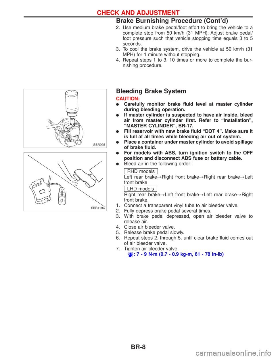
lBleed air in the following order:
RHD models
Left rear brake,Right front brake,Right rear brake,Left
front brake
LHD models
Right rear brake,Left front brake,Left rear brake,Right
front brake.
1. Connect a transparent vinyl tube to air bleeder valve.
2. Fully depress brake pedal several times.
3. With brake pedal depressed, open air bleeder valve to
release air.
4. Close air bleeder valve.
5. Release brake pedal slowly.
6. Repeat steps 2. through 5. until clear brake fluid comes out
of air bleeder valve.
7. Tighten air bleeder valve.
:7-9N´m(0.7 - 0.9 kg-m, 61 - 78 in-lb)
SBR995
SBR419C
CHECK AND ADJUSTMENT
Brake Burnishing Procedure (Cont'd)
BR-8
Page 172 of 2267
Purpose
The Anti-Lock Brake System (ABS) consists of electronic and hydraulic components. It allows for control of
braking force so that locking of the wheels can be avoided.
The ABS:
1) Provides improved steering control during braking (by preventing front wheel lock).
2) Provides improved vehicle stability and skid prevention during braking (by avoiding rear wheel lock).
Operation
lWhen the vehicle speed is less than 10 km/h (6 mph) this system does not work.
lThe Anti-Lock Brake System (ABS) has self-test capabilities. The system turns on the ABS warning light
for 1 second after turning the ignition switch to the ªONº position. The system performs another test the
first time the vehicle reaches 6 km/h (4 mph). A mechanical noise may be heard as the ABS performs
a self-test. This is a normal part of the self-test feature. If a malfunction is found during this check, the
ABS warning light will come on.
lDuring ABS operation, a mechanical noise may be heard. This is a normal operating condition.
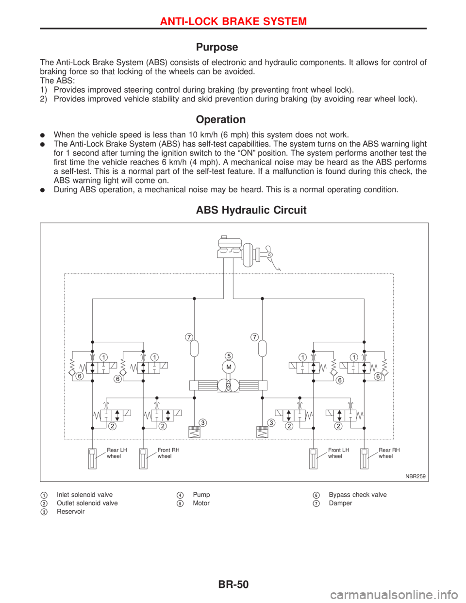
ABS Hydraulic Circuit
p1Inlet solenoid valve
p2Outlet solenoid valve
p3Reservoir
p4Pump
p5Motorp6Bypass check valve
p7Damper
NBR259 Rear LH
wheelFront RH
wheelFront LH
wheelRear RH
wheel
ANTI-LOCK BRAKE SYSTEM
BR-50
Page 181 of 2267
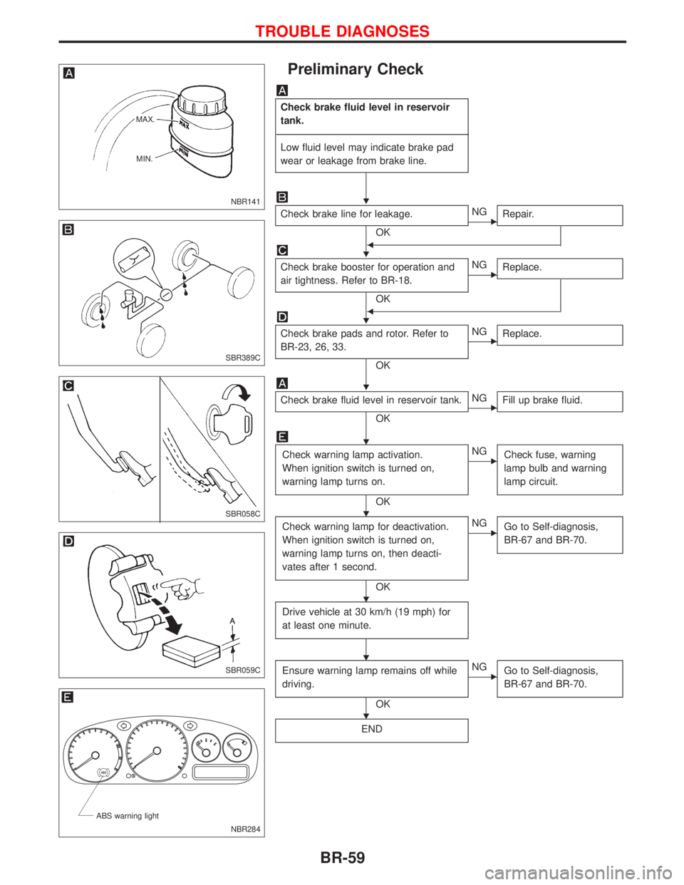
Preliminary Check
Check brake fluid level in reservoir
tank.
------------------------------------------------------------------------------------------------------------------------------------------------------------------------------------------------------------------------------------------------------------------------------------------------------------
Low fluid level may indicate brake pad
wear or leakage from brake line.
Check brake line for leakage.
OK
ENG
Repair.
F
Check brake booster for operation and
air tightness. Refer to BR-18.
OK
ENG
Replace.
F
Check brake pads and rotor. Refer to
BR-23, 26, 33.
OK
ENG
Replace.
Check brake fluid level in reservoir tank.
OK
ENG
Fill up brake fluid.
Check warning lamp activation.
When ignition switch is turned on,
warning lamp turns on.
OK
ENG
Check fuse, warning
lamp bulb and warning
lamp circuit.
Check warning lamp for deactivation.
When ignition switch is turned on,
warning lamp turns on, then deacti-
vates after 1 second.
OK
ENG
Go to Self-diagnosis,
BR-67 and BR-70.
Drive vehicle at 30 km/h (19 mph) for
at least one minute.
Ensure warning lamp remains off while
driving.
OK
ENG
Go to Self-diagnosis,
BR-67 and BR-70.
END
NBR141 MAX.
MIN.
SBR389C
SBR058C
SBR059C
.
NBR284 ABS warning light
H
H
H
H
H
H
H
H
H
TROUBLE DIAGNOSES
BR-59
Page 184 of 2267
Wiring Diagram Ð ABS Ð
MODELS WITH SELF-DIAGNOSIS FUNCTION
YBR208 BATTERYIGNITION SWITCH
ON or START
FUSE
BLOCK
(J/B)Refer to EL-POWER.
: LHD models
: RHD models: CVT models
: M/T models
RELEASEDDEPRESSEDSTOP LAMP
SWITCH
FUSE
BLOCK
(J/B)COMBINATION METER
(ABS WARNING LAMP)
ABS ACTUATOR
AND ELECTRIC
UNIT
(CONTROL UNIT)
TCM
(TRANSMISSION CON-
TROL MODULE)DATA LINK CON-
NECTOR
Refer to las page (Foldout page).
TROUBLE DIAGNOSES
BR-62
Page 189 of 2267
Self-diagnosis (Only models with data link
connector terminal No. 8)
FUNCTION
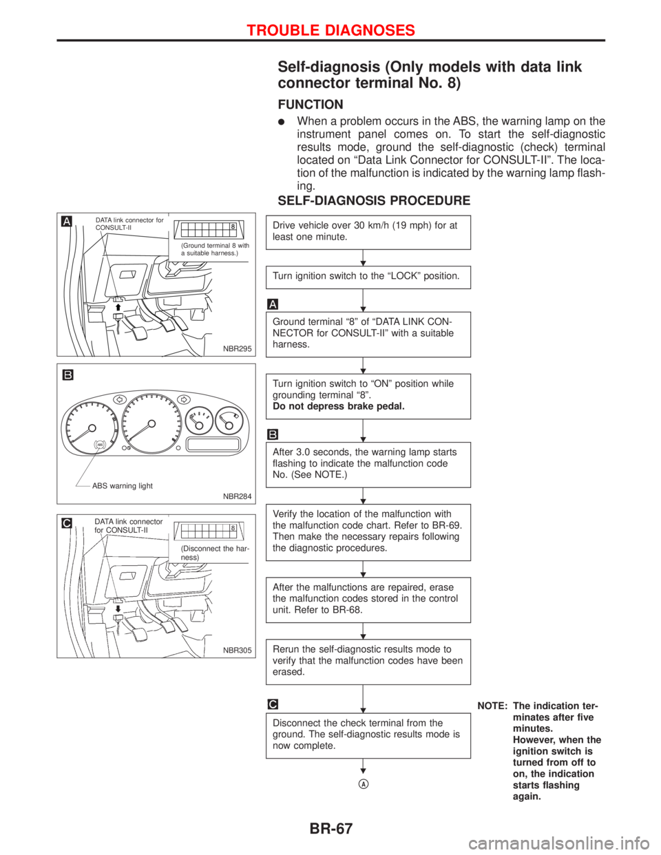
lWhen a problem occurs in the ABS, the warning lamp on the
instrument panel comes on. To start the self-diagnostic
results mode, ground the self-diagnostic (check) terminal
located on ªData Link Connector for CONSULT-IIº. The loca-
tion of the malfunction is indicated by the warning lamp flash-
ing.
SELF-DIAGNOSIS PROCEDURE
Drive vehicle over 30 km/h (19 mph) for at
least one minute.
Turn ignition switch to the ªLOCKº position.
Ground terminal ª8º of ªDATA LINK CON-
NECTOR for CONSULT-IIº with a suitable
harness.
Turn ignition switch to ªONº position while
grounding terminal ª8º.
Do not depress brake pedal.
After 3.0 seconds, the warning lamp starts
flashing to indicate the malfunction code
No. (See NOTE.)
Verify the location of the malfunction with
the malfunction code chart. Refer to BR-69.
Then make the necessary repairs following
the diagnostic procedures.
After the malfunctions are repaired, erase
the malfunction codes stored in the control
unit. Refer to BR-68.
Rerun the self-diagnostic results mode to
verify that the malfunction codes have been
erased.
NOTE: The indication ter-
minates after five
minutes.
However, when the
ignition switch is
turned from off to
on, the indication
starts flashing
again. Disconnect the check terminal from the
ground. The self-diagnostic results mode is
now complete.
pA
NBR295
.DATA link connector for
CONSULT-II
(Ground terminal 8 with
a suitable harness.)
NBR284 ABS warning light
NBR305
.DATA link connector
for CONSULT-II
(Disconnect the har-
ness)
H
H
H
H
H
H
H
H
H
TROUBLE DIAGNOSES
BR-67
Page 192 of 2267
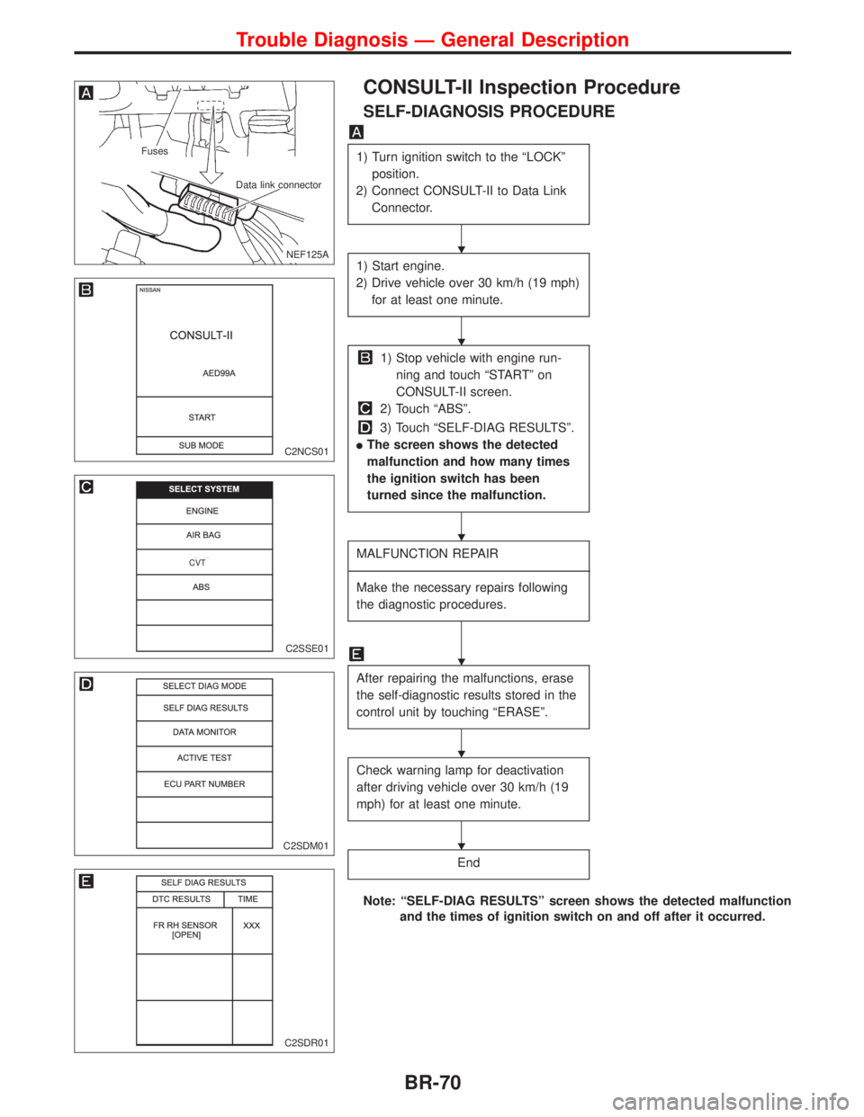
CONSULT-II Inspection Procedure
SELF-DIAGNOSIS PROCEDURE
1) Turn ignition switch to the ªLOCKº
position.
2) Connect CONSULT-II to Data Link
Connector.
1) Start engine.
2) Drive vehicle over 30 km/h (19 mph)
for at least one minute.
1) Stop vehicle with engine run-
ning and touch ªSTARTº on
CONSULT-II screen.
2) Touch ªABSº.
3) Touch ªSELF-DIAG RESULTSº.
lThe screen shows the detected
malfunction and how many times
the ignition switch has been
turned since the malfunction.
MALFUNCTION REPAIR
----------------------------------------------------------------------------------------------------------------------------------------------------------------------------------------------------------------------------------------------------------------------------------------------------------
Make the necessary repairs following
the diagnostic procedures.
After repairing the malfunctions, erase
the self-diagnostic results stored in the
control unit by touching ªERASEº.
Check warning lamp for deactivation
after driving vehicle over 30 km/h (19
mph) for at least one minute.
End
Note: ªSELF-DIAG RESULTSº screen shows the detected malfunction
and the times of ignition switch on and off after it occurred.
.NEF125A
Fuses
Data link connector
C2NCS01
C2SSE01
.CVT
C2SDM01
C2SDR01
H
H
H
H
H
H
Trouble Diagnosis Ð General Description
BR-70
Page 194 of 2267
DATA MONITOR PROCEDURE
1) Turn ignition switch to the off position.
2) Connect CONSULT-II to Data Link Connector.
3) Turn ignition switch to the ON position.
1) Touch ªSTARTº on CONSULT-II screen.
2) Touch ªABSº.
3) Touch ªDATA MONITORº.
1) Select ªSELECT MONITOR ITEMº.
Carry out the monitor test under the condition as described in page BR-73.
C2NCS01
C2SSE01
C2SDM01
C2SMI01
H
H
H
Trouble Diagnosis Ð General Description
CONSULT-II Inspection Procedure (Cont'd)
BR-72
Page 195 of 2267
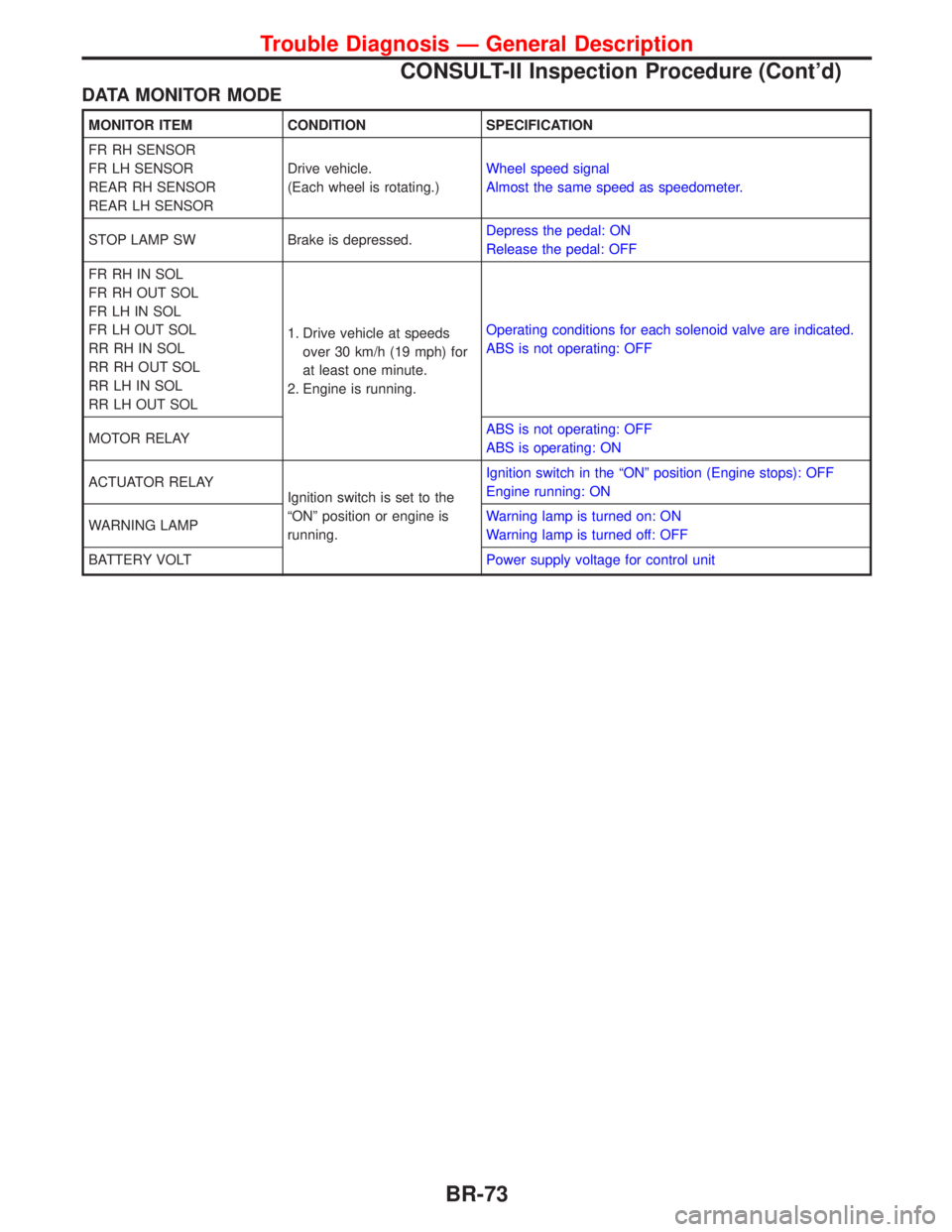
DATA MONITOR MODE
MONITOR ITEM CONDITION SPECIFICATION
FR RH SENSOR
FR LH SENSOR
REAR RH SENSOR
REAR LH SENSORDrive vehicle.
(Each wheel is rotating.)Wheel speed signal
Almost the same speed as speedometer.
STOP LAMP SW Brake is depressed.Depress the pedal: ON
Release the pedal: OFF
FR RH IN SOL
FR RH OUT SOL
FR LH IN SOL
FR LH OUT SOL
RR RH IN SOL
RR RH OUT SOL
RR LH IN SOL
RR LH OUT SOL1. Drive vehicle at speeds
over 30 km/h (19 mph) for
at least one minute.
2. Engine is running.Operating conditions for each solenoid valve are indicated.
ABS is not operating: OFF
MOTOR RELAYABS is not operating: OFF
ABS is operating: ON
ACTUATOR RELAY
Ignition switch is set to the
ªONº position or engine is
running.Ignition switch in the ªONº position (Engine stops): OFF
Engine running: ON
WARNING LAMPWarning lamp is turned on: ON
Warning lamp is turned off: OFF
BATTERY VOLTPower supply voltage for control unit
Trouble Diagnosis Ð General Description
CONSULT-II Inspection Procedure (Cont'd)
BR-73