1999 NISSAN PRIMERA ignition
[x] Cancel search: ignitionPage 325 of 2267
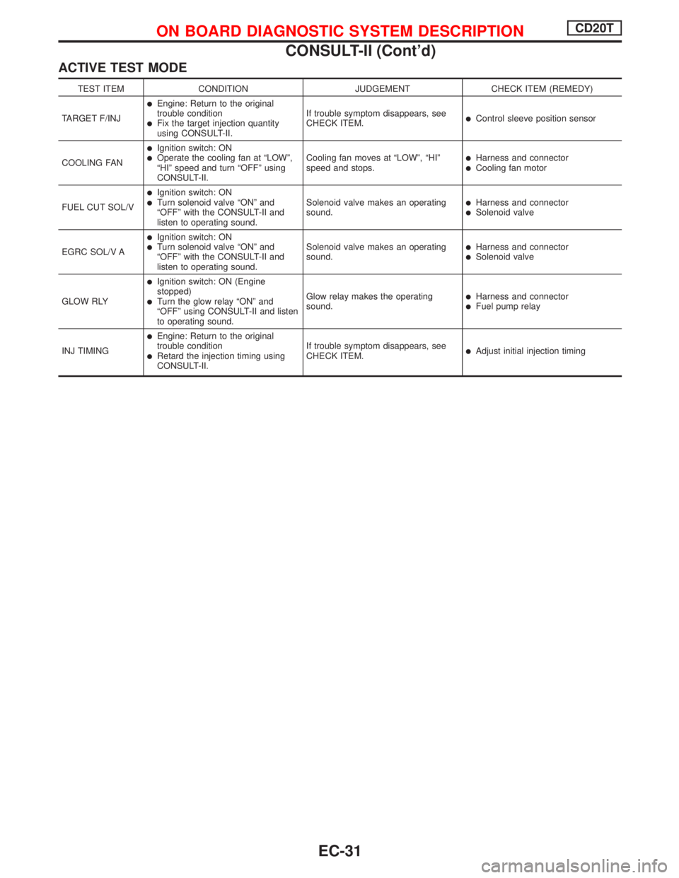
ACTIVE TEST MODE
TEST ITEM CONDITION JUDGEMENT CHECK ITEM (REMEDY)
TARGET F/INJ
lEngine: Return to the original
trouble condition
lFix the target injection quantity
using CONSULT-II.If trouble symptom disappears, see
CHECK ITEM.lControl sleeve position sensor
COOLING FAN
lIgnition switch: ONlOperate the cooling fan at ªLOWº,
ªHIº speed and turn ªOFFº using
CONSULT-II.Cooling fan moves at ªLOWº, ªHIº
speed and stops.lHarness and connectorlCooling fan motor
FUEL CUT SOL/V
lIgnition switch: ONlTurn solenoid valve ªONº and
ªOFFº with the CONSULT-II and
listen to operating sound.Solenoid valve makes an operating
sound.lHarness and connectorlSolenoid valve
EGRC SOL/V A
lIgnition switch: ONlTurn solenoid valve ªONº and
ªOFFº with the CONSULT-II and
listen to operating sound.Solenoid valve makes an operating
sound.lHarness and connectorlSolenoid valve
GLOW RLY
lIgnition switch: ON (Engine
stopped)
lTurn the glow relay ªONº and
ªOFFº using CONSULT-II and listen
to operating sound.Glow relay makes the operating
sound.lHarness and connectorlFuel pump relay
INJ TIMING
lEngine: Return to the original
trouble condition
lRetard the injection timing using
CONSULT-II.If trouble symptom disappears, see
CHECK ITEM.lAdjust initial injection timing
ON BOARD DIAGNOSTIC SYSTEM DESCRIPTIONCD20T
CONSULT-II (Cont'd)
EC-31
Page 331 of 2267
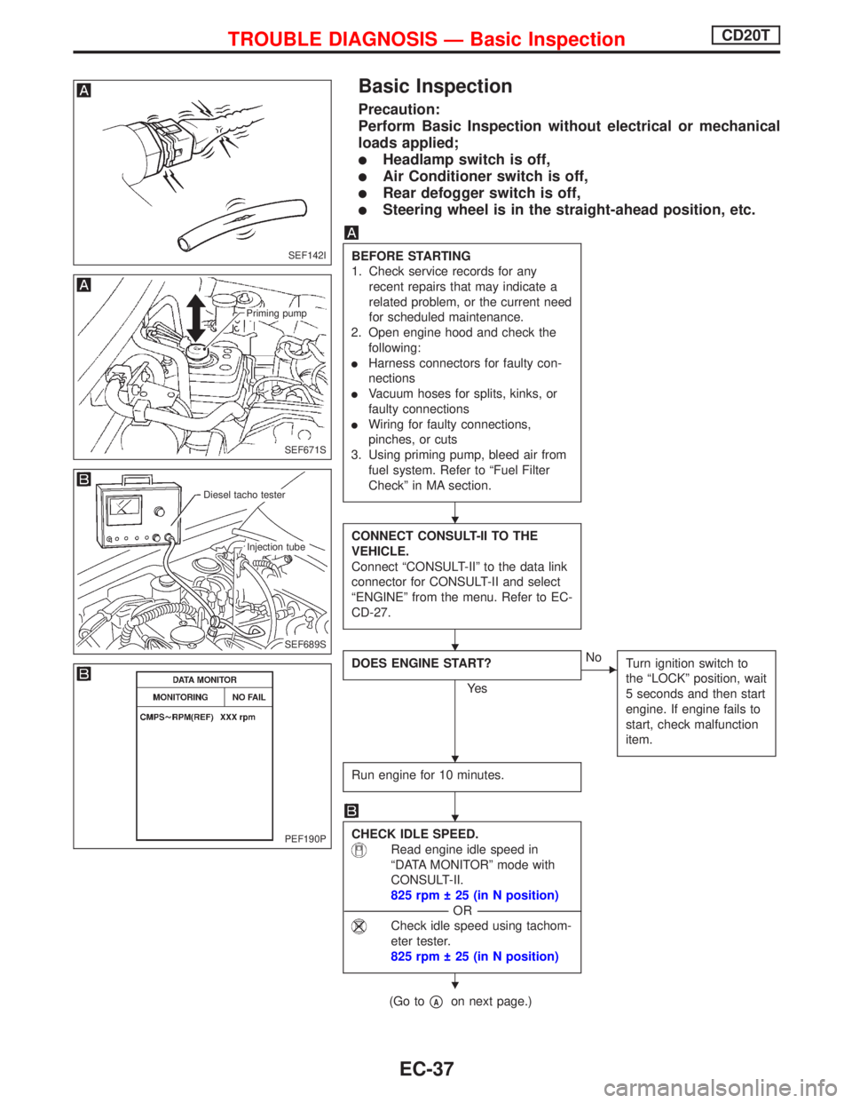
Basic Inspection
Precaution:
Perform Basic Inspection without electrical or mechanical
loads applied;
lHeadlamp switch is off,
lAir Conditioner switch is off,
lRear defogger switch is off,
lSteering wheel is in the straight-ahead position, etc.
BEFORE STARTING
1. Check service records for any
recent repairs that may indicate a
related problem, or the current need
for scheduled maintenance.
2. Open engine hood and check the
following:
lHarness connectors for faulty con-
nections
lVacuum hoses for splits, kinks, or
faulty connections
lWiring for faulty connections,
pinches, or cuts
3. Using priming pump, bleed air from
fuel system. Refer to ªFuel Filter
Checkº in MA section.
CONNECT CONSULT-II TO THE
VEHICLE.
Connect ªCONSULT-IIº to the data link
connector for CONSULT-II and select
ªENGINEº from the menu. Refer to EC-
CD-27.
DOES ENGINE START?
Ye s
ENo
Turn ignition switch to
the ªLOCKº position, wait
5 seconds and then start
engine. If engine fails to
start, check malfunction
item.
Run engine for 10 minutes.
CHECK IDLE SPEED.
Read engine idle speed in
ªDATA MONITORº mode with
CONSULT-II.
825 rpm 25 (in N position)
---------------------------------------------------------------------------------------------------------------------------------OR---------------------------------------------------------------------------------------------------------------------------------
Check idle speed using tachom-
eter tester.
825 rpm 25 (in N position)
(Go topAon next page.)
SEF142I
SEF671S
Priming pump
SEF689S
.Diesel tacho tester
.Injection tube
PEF190P
H
H
H
H
H
TROUBLE DIAGNOSIS Ð Basic InspectionCD20T
EC-37
Page 333 of 2267
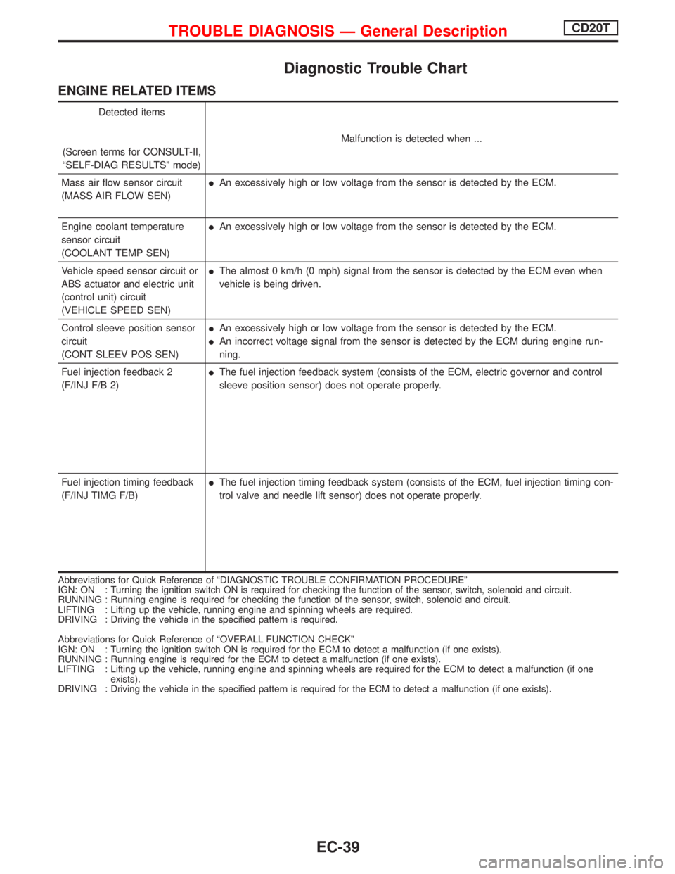
Diagnostic Trouble Chart
ENGINE RELATED ITEMS
Detected items
(Screen terms for CONSULT-II,
ªSELF-DIAG RESULTSº mode)Malfunction is detected when ...
Mass air flow sensor circuit
(MASS AIR FLOW SEN)
lAn excessively high or low voltage from the sensor is detected by the ECM.
Engine coolant temperature
sensor circuit
(COOLANT TEMP SEN)
lAn excessively high or low voltage from the sensor is detected by the ECM.
Vehicle speed sensor circuit or
ABS actuator and electric unit
(control unit) circuit
(VEHICLE SPEED SEN)
lThe almost 0 km/h (0 mph) signal from the sensor is detected by the ECM even when
vehicle is being driven.
Control sleeve position sensor
circuit
(CONT SLEEV POS SEN)
lAn excessively high or low voltage from the sensor is detected by the ECM.
lAn incorrect voltage signal from the sensor is detected by the ECM during engine run-
ning.
Fuel injection feedback 2
(F/INJ F/B 2)
lThe fuel injection feedback system (consists of the ECM, electric governor and control
sleeve position sensor) does not operate properly.
Fuel injection timing feedback
(F/INJ TIMG F/B)
lThe fuel injection timing feedback system (consists of the ECM, fuel injection timing con-
trol valve and needle lift sensor) does not operate properly.
Abbreviations for Quick Reference of ªDIAGNOSTIC TROUBLE CONFIRMATION PROCEDUREº
IGN: ON : Turning the ignition switch ON is required for checking the function of the sensor, switch, solenoid and circuit.
RUNNING : Running engine is required for checking the function of the sensor, switch, solenoid and circuit.
LIFTING : Lifting up the vehicle, running engine and spinning wheels are required.
DRIVING : Driving the vehicle in the specified pattern is required.
Abbreviations for Quick Reference of ªOVERALL FUNCTION CHECKº
IGN: ON : Turning the ignition switch ON is required for the ECM to detect a malfunction (if one exists).
RUNNING : Running engine is required for the ECM to detect a malfunction (if one exists).
LIFTING : Lifting up the vehicle, running engine and spinning wheels are required for the ECM to detect a malfunction (if one
exists).
DRIVING : Driving the vehicle in the specified pattern is required for the ECM to detect a malfunction (if one exists).
TROUBLE DIAGNOSIS Ð General DescriptionCD20T
EC-39
Page 335 of 2267
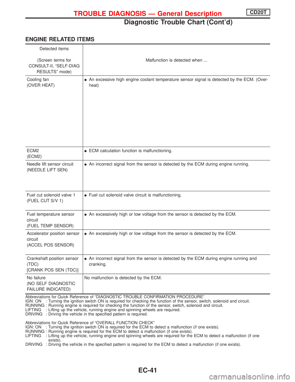
ENGINE RELATED ITEMS
Detected items
(Screen terms for
CONSULT-II, ªSELF-DIAG
RESULTSº mode)Malfunction is detected when ...
Cooling fan
(OVER HEAT)
lAn excessive high engine coolant temperature sensor signal is detected by the ECM. (Over-
heat)
ECM2
(ECM2)
lECM calculation function is malfunctioning.
Needle lift sensor circuit
(NEEDLE LIFT SEN)
lAn incorrect signal from the sensor is detected by the ECM during engine running.
Fuel cut solenoid valve 1
(FUEL CUT S/V 1)
lFuel cut solenoid valve circuit is malfunctioning.
Fuel temperature sensor
circuit
(FUEL TEMP SENSOR)
lAn excessively high or low voltage from the sensor is detected by the ECM.
Accelerator position sensor
circuit
(ACCEL POS SENSOR)
lAn excessively high or low voltage from the sensor is detected by the ECM.
Crankshaft position sensor
(TDC)
[CRANK POS SEN (TDC)]
lAn incorrect signal from the sensor is detected by the ECM during engine running and
cranking.
No failure
(NO SELF DIAGNOSTIC
FAILURE INDICATED)No malfunction is detected by the ECM.
Abbreviations for Quick Reference of ªDIAGNOSTIC TROUBLE CONFIRMATION PROCEDUREº
IGN: ON : Turning the ignition switch ON is required for checking the function of the sensor, switch, solenoid and circuit.
RUNNING : Running engine is required for checking the function of the sensor, switch, solenoid and circuit.
LIFTING : Lifting up the vehicle, running engine and spinning wheels are required.
DRIVING : Driving the vehicle in the specified pattern is required.
Abbreviations for Quick Reference of ªOVERALL FUNCTION CHECKº
IGN: ON : Turning the ignition switch ON is required for the ECM to detect a malfunction (if one exists).
RUNNING : Running engine is required for the ECM to detect a malfunction (if one exists).
LIFTING : Lifting up the vehicle, running engine and spinning wheels are required for the ECM to detect a malfunction (if one
exists).
DRIVING : Driving the vehicle in the specified pattern is required for the ECM to detect a malfunction (if one exists).
TROUBLE DIAGNOSIS Ð General DescriptionCD20T
Diagnostic Trouble Chart (Cont'd)
EC-41
Page 337 of 2267
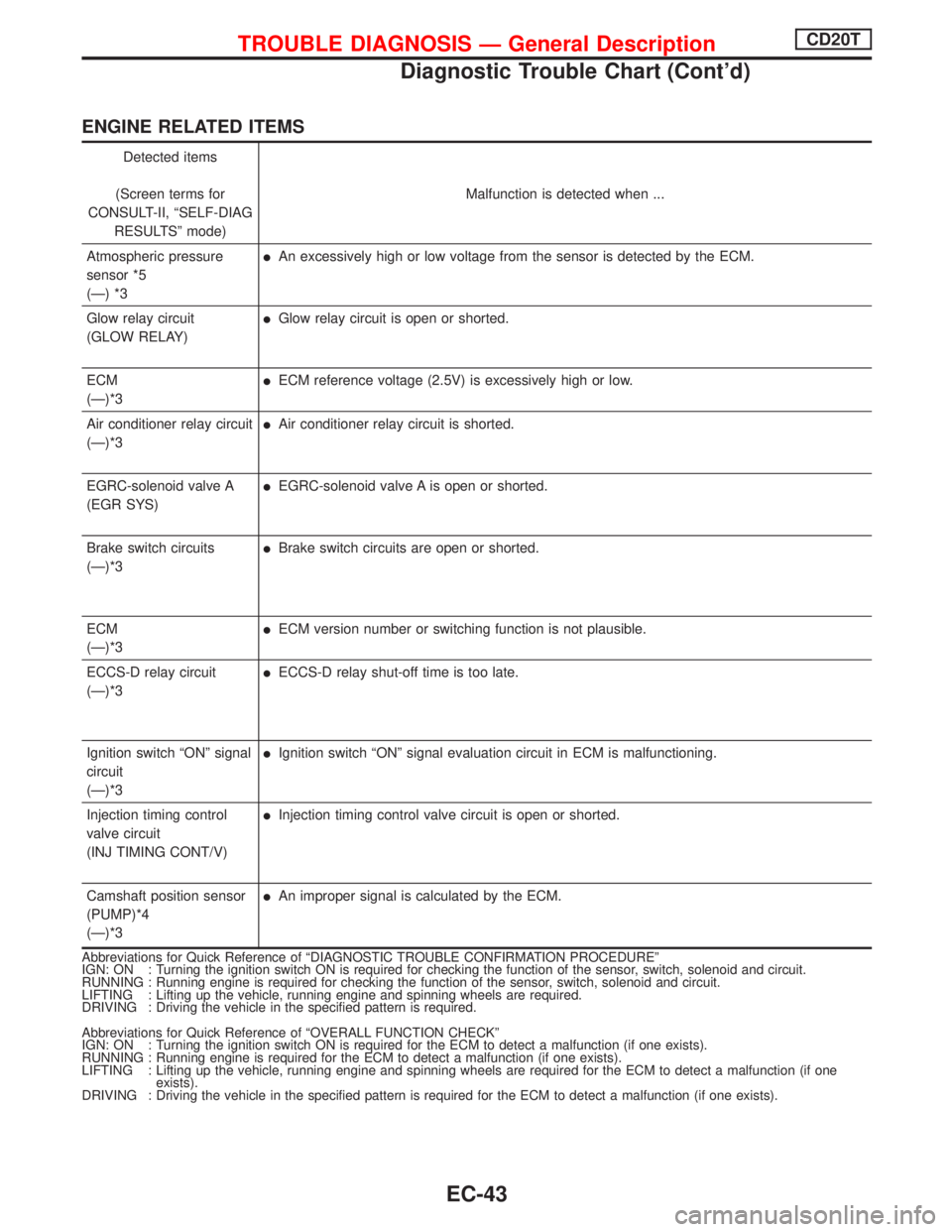
ENGINE RELATED ITEMS
Detected items
(Screen terms for
CONSULT-II, ªSELF-DIAG
RESULTSº mode)Malfunction is detected when ...
Atmospheric pressure
sensor *5
(Ð) *3
lAn excessively high or low voltage from the sensor is detected by the ECM.
Glow relay circuit
(GLOW RELAY)
lGlow relay circuit is open or shorted.
ECM
(Ð)*3
lECM reference voltage (2.5V) is excessively high or low.
Air conditioner relay circuit
(Ð)*3
lAir conditioner relay circuit is shorted.
EGRC-solenoid valve A
(EGR SYS)
lEGRC-solenoid valve A is open or shorted.
Brake switch circuits
(Ð)*3
lBrake switch circuits are open or shorted.
ECM
(Ð)*3
lECM version number or switching function is not plausible.
ECCS-D relay circuit
(Ð)*3
lECCS-D relay shut-off time is too late.
Ignition switch ªONº signal
circuit
(Ð)*3
lIgnition switch ªONº signal evaluation circuit in ECM is malfunctioning.
Injection timing control
valve circuit
(INJ TIMING CONT/V)
lInjection timing control valve circuit is open or shorted.
Camshaft position sensor
(PUMP)*4
(Ð)*3
lAn improper signal is calculated by the ECM.
Abbreviations for Quick Reference of ªDIAGNOSTIC TROUBLE CONFIRMATION PROCEDUREº
IGN: ON : Turning the ignition switch ON is required for checking the function of the sensor, switch, solenoid and circuit.
RUNNING : Running engine is required for checking the function of the sensor, switch, solenoid and circuit.
LIFTING : Lifting up the vehicle, running engine and spinning wheels are required.
DRIVING : Driving the vehicle in the specified pattern is required.
Abbreviations for Quick Reference of ªOVERALL FUNCTION CHECKº
IGN: ON : Turning the ignition switch ON is required for the ECM to detect a malfunction (if one exists).
RUNNING : Running engine is required for the ECM to detect a malfunction (if one exists).
LIFTING : Lifting up the vehicle, running engine and spinning wheels are required for the ECM to detect a malfunction (if one
exists).
DRIVING : Driving the vehicle in the specified pattern is required for the ECM to detect a malfunction (if one exists).
TROUBLE DIAGNOSIS Ð General DescriptionCD20T
Diagnostic Trouble Chart (Cont'd)
EC-43
Page 339 of 2267
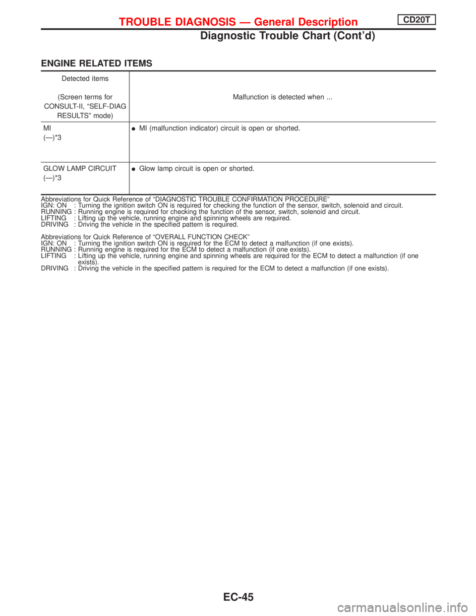
ENGINE RELATED ITEMS
Detected items
(Screen terms for
CONSULT-II, ªSELF-DIAG
RESULTSº mode)Malfunction is detected when ...
MI
(Ð)*3
lMI (malfunction indicator) circuit is open or shorted.
GLOW LAMP CIRCUIT
(Ð)*3
lGlow lamp circuit is open or shorted.
Abbreviations for Quick Reference of ªDIAGNOSTIC TROUBLE CONFIRMATION PROCEDUREº
IGN: ON : Turning the ignition switch ON is required for checking the function of the sensor, switch, solenoid and circuit.
RUNNING : Running engine is required for checking the function of the sensor, switch, solenoid and circuit.
LIFTING : Lifting up the vehicle, running engine and spinning wheels are required.
DRIVING : Driving the vehicle in the specified pattern is required.
Abbreviations for Quick Reference of ªOVERALL FUNCTION CHECKº
IGN: ON : Turning the ignition switch ON is required for the ECM to detect a malfunction (if one exists).
RUNNING : Running engine is required for the ECM to detect a malfunction (if one exists).
LIFTING : Lifting up the vehicle, running engine and spinning wheels are required for the ECM to detect a malfunction (if one
exists).
DRIVING : Driving the vehicle in the specified pattern is required for the ECM to detect a malfunction (if one exists).
TROUBLE DIAGNOSIS Ð General DescriptionCD20T
Diagnostic Trouble Chart (Cont'd)
EC-45
Page 342 of 2267
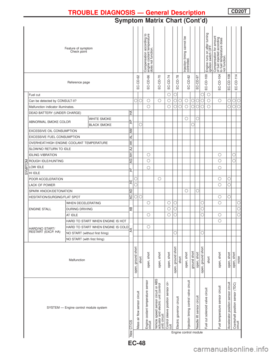
SYSTEM Ð Engine control module systemMalfunction
SYMPTOM
Reference page Feature of symptom
Check point
HARD/NO START/
RESTART (EXCP. HA) ENGINE STALL HESITATION/SURGING/FLAT SPOT SPARK KNOCK/DETONATION
LACK OF POWER
POOR ACCELERATION
HI IDLE
LOW IDLE
ROUGH IDLE/HUNTING
IDLING VIBRATION
SLOW/NO RETURN TO IDLE
OVERHEAT/HIGH ENGINE COOLANT TEMPERATURE
EXCESSIVE FUEL CONSUMPTION
EXCESSIVE OIL CONSUMPTION ABNORMAL SMOKE COLOR
DEAD BATTERY (UNDER CHARGE) Malfunction indicator illuminates.
Can be detected by CONSULT-II?
Fuel cut
NO START (with first firing) NO START (without first firing)
HARD TO START WHEN ENGINE IS COLD
HARD TO START WHEN ENGINE IS HOT
AT IDLE
DURING DRIVING
WHEN DECELERATINGBLACK SMOKE WHITE SMOKE
New CT/CS AA AB AC AD AE AF AG AH AJ AK AL AM AP HAEngine control moduleMass air flow sensor circuitopen, ground shortqqq q
EC-CD-62
shortqqq
Engine coolant temperature sensor
circuitopen, shortqqq qqq qqEC-CD-66Compensation according to
engine coolant temperature
does not function.
Vehicle speed sensor circuit or ABS
actuator and electric unit (control
unit) circuitopen, shortqqEC-CD-70
Control sleeve position sensor cir-
cuitopen, shortqqq qqqEC-CD-74
Electric governor circuitopen, ground shortq qqq qqq
EC-CD-78
shortqq
Injection timing control valve circuitopen, shortqqqq
EC-CD-82Injection timing cannot be
controlled.
ground shortqqq
Needle lift sensor circuit open, shortqqqqEC-CD-97
Fuel cut solenoid valve circuitopen, ground shortq qqq qqq
EC-CD-100
shortqqqEngine runs on after turning
ignition switch OFF.
Fuel temperature sensor circuit open, shortqq qq qq q qq qEC-CD-104Compensation for amount
of fuel injected according
to fuel temperature does
not function.
Accelerator position sensor circuit open, shortqqq qqEC-CD-108
Crankshaft position sensor (TDC)
circuitopen, shortqq qq
EC-CD-114
noiseqqq qq
TROUBLE DIAGNOSIS Ð General DescriptionCD20T
Symptom Matrix Chart (Cont'd)
EC-48
Page 343 of 2267
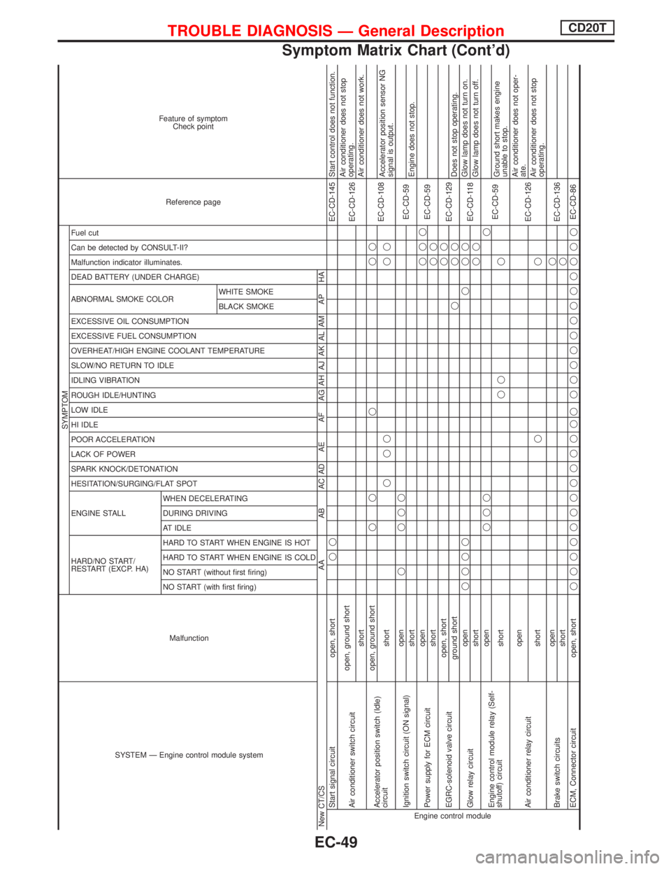
SYSTEM Ð Engine control module systemMalfunction
SYMPTOM
Reference page Feature of symptom
Check point
HARD/NO START/
RESTART (EXCP. HA) ENGINE STALL HESITATION/SURGING/FLAT SPOT SPARK KNOCK/DETONATION
LACK OF POWER
POOR ACCELERATION
HI IDLE
LOW IDLE
ROUGH IDLE/HUNTING
IDLING VIBRATION
SLOW/NO RETURN TO IDLE
OVERHEAT/HIGH ENGINE COOLANT TEMPERATURE
EXCESSIVE FUEL CONSUMPTION
EXCESSIVE OIL CONSUMPTION ABNORMAL SMOKE COLOR
DEAD BATTERY (UNDER CHARGE) Malfunction indicator illuminates.
Can be detected by CONSULT-II?
Fuel cut
NO START (with first firing) NO START (without first firing)
HARD TO START WHEN ENGINE IS COLD
HARD TO START WHEN ENGINE IS HOT
AT IDLE
DURING DRIVING
WHEN DECELERATINGBLACK SMOKE WHITE SMOKE
New CT/CS AA AB AC AD AE AF AG AH AJ AK AL AM AP HAEngine control moduleStart signal circuit open, shortqqEC-CD-145 Start control does not function.
Air conditioner switch circuitopen, ground short
EC-CD-126Air conditioner does not stop
operating.
shortAir conditioner does not work.
Accelerator position switch (Idle)
circuitopen, ground shortqq q qq
EC-CD-108
shortqqq qqAccelerator position sensor NG
signal is output.
Ignition switch circuit (ON signal)openq qqq
EC-CD-59
shortEngine does not stop.
Power supply for ECM circuitopenqqq
EC-CD-59
shortqq
EGRC-solenoid valve circuitopen, shortqq
EC-CD-129
ground shortqqqDoes not stop operating.
Glow relay circuitopenqqqq q qq
EC-CD-118Glow lamp does not turn on.
shortqqGlow lamp does not turn off.
Engine control module relay (Self-
shutoff) circuitopenqqqq
EC-CD-59
shortqq qGround short makes engine
unable to stop.
Air conditioner relay circuitopen
EC-CD-126Air conditioner does not oper-
ate.
shortqqAir conditioner does not stop
operating.
Brake switch circuitsopenq
EC-CD-136
shortq
ECM, Connector circuit open, shortqqqqqqqqqqqqq qqqqqqqqqqqqEC-CD-86
TROUBLE DIAGNOSIS Ð General DescriptionCD20T
Symptom Matrix Chart (Cont'd)
EC-49