Page 196 of 2267
ACTIVE TEST PROCEDURE
lWhen conducting Active test, vehicle must be stationary.
lWhen ABS warning lamp stays on, never conduct Active test.
1) Turn ignition switch to the ªLOCKº position.
2) Connect CONSULT-II to Data Link Connector.
3) Start engine.
1) Touch ªSTARTº on CONSULT-II screen.
2) Touch ªABSº.
3) Touch ªACTIVE TESTº.
1) Select active test item by touching screen.
2) Touch ªSTARTº.
Carry out the active test by touching screen key.
C2NCS01
C2SSE01
.CVT
C2SDM01
C2STI01
C2FRS01
H
H
H
Trouble Diagnosis Ð General Description
CONSULT-II Inspection Procedure (Cont'd)
BR-74
Page 198 of 2267
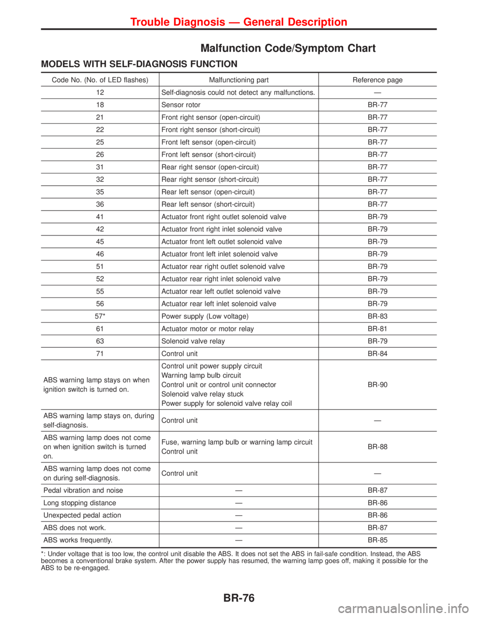
Malfunction Code/Symptom Chart
MODELS WITH SELF-DIAGNOSIS FUNCTION
Code No. (No. of LED flashes) Malfunctioning part Reference page
12 Self-diagnosis could not detect any malfunctions. Ð
18 Sensor rotor BR-77
21 Front right sensor (open-circuit) BR-77
22 Front right sensor (short-circuit) BR-77
25 Front left sensor (open-circuit) BR-77
26 Front left sensor (short-circuit) BR-77
31 Rear right sensor (open-circuit) BR-77
32 Rear right sensor (short-circuit) BR-77
35 Rear left sensor (open-circuit) BR-77
36 Rear left sensor (short-circuit) BR-77
41 Actuator front right outlet solenoid valve BR-79
42 Actuator front right inlet solenoid valve BR-79
45 Actuator front left outlet solenoid valve BR-79
46 Actuator front left inlet solenoid valve BR-79
51 Actuator rear right outlet solenoid valve BR-79
52 Actuator rear right inlet solenoid valve BR-79
55 Actuator rear left outlet solenoid valve BR-79
56 Actuator rear left inlet solenoid valve BR-79
57* Power supply (Low voltage) BR-83
61 Actuator motor or motor relay BR-81
63 Solenoid valve relay BR-79
71 Control unit BR-84
ABS warning lamp stays on when
ignition switch is turned on.Control unit power supply circuit
Warning lamp bulb circuit
Control unit or control unit connector
Solenoid valve relay stuck
Power supply for solenoid valve relay coilBR-90
ABS warning lamp stays on, during
self-diagnosis.Control unit Ð
ABS warning lamp does not come
on when ignition switch is turned
on.Fuse, warning lamp bulb or warning lamp circuit
Control unitBR-88
ABS warning lamp does not come
on during self-diagnosis.Control unit Ð
Pedal vibration and noise Ð BR-87
Long stopping distance Ð BR-86
Unexpected pedal action Ð BR-86
ABS does not work. Ð BR-87
ABS works frequently. Ð BR-85
*: Under voltage that is too low, the control unit disable the ABS. It does not set the ABS in fail-safe condition. Instead, the ABS
becomes a conventional brake system. After the power supply has resumed, the warning lamp goes off, making it possible for the
ABS to be re-engaged.
Trouble Diagnosis Ð General Description
BR-76
Page 202 of 2267
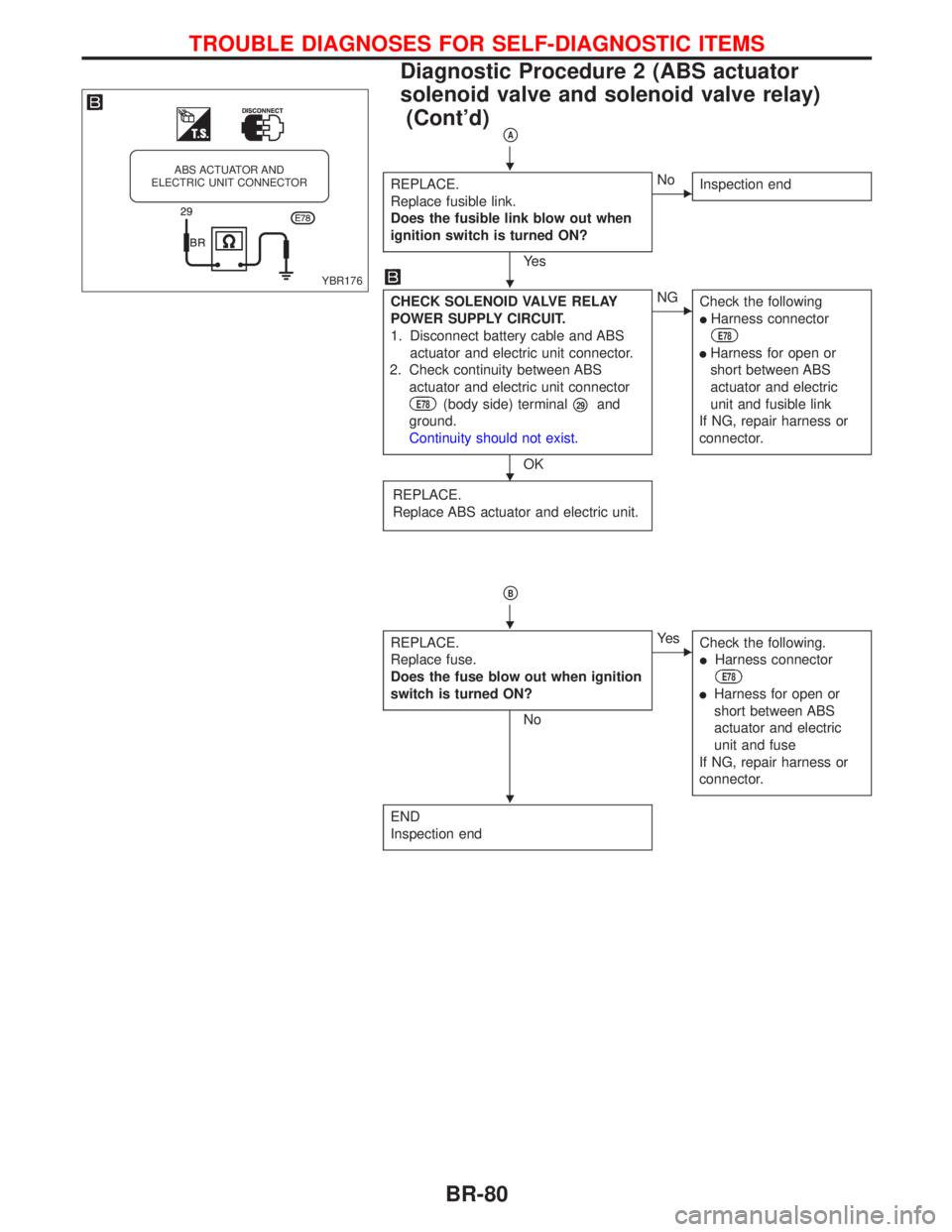
pA
REPLACE.
Replace fusible link.
Does the fusible link blow out when
ignition switch is turned ON?
Ye s
ENo
Inspection end
CHECK SOLENOID VALVE RELAY
POWER SUPPLY CIRCUIT.
1. Disconnect battery cable and ABS
actuator and electric unit connector.
2. Check continuity between ABS
actuator and electric unit connector
E78(body side) terminalp29and
ground.
Continuity should not exist.
OK
ENG
Check the following
lHarness connector
E78
lHarness for open or
short between ABS
actuator and electric
unit and fusible link
If NG, repair harness or
connector.
REPLACE.
Replace ABS actuator and electric unit.
pB
REPLACE.
Replace fuse.
Does the fuse blow out when ignition
switch is turned ON?
No
EYe s
Check the following.
lHarness connector
E78
lHarness for open or
short between ABS
actuator and electric
unit and fuse
If NG, repair harness or
connector.
END
Inspection end
YBR176
ABS ACTUATOR AND
ELECTRIC UNIT CONNECTORH
H
H
H
H
TROUBLE DIAGNOSES FOR SELF-DIAGNOSTIC ITEMS
Diagnostic Procedure 2 (ABS actuator
solenoid valve and solenoid valve relay)
(Cont'd)
BR-80
Page 204 of 2267
pA
REPLACE.
Replace fusible link.
Does the fusible link blow out when
ignition switch is turned ON?
OK
ENo
Inspection end
CHECK ABS ACTUATOR MOTOR
POWER SUPPLY CIRCUIT.
1. Disconnect battery cable and ABS
actuator and electric unit connector
E78.
2. Check continuity between ABS
actuator and electric unit connector
E78(body side) terminalp30and
ground.
Continuity should not exist.
OK
ENG
Check the following
lHarness connector
E78
lHarness for open or
short between ABS
actuator and electric
unit and fusible link
If NG, repair harness ro
connector.
CHECK HARNESS CONNECTOR.
Check ABS actuator and electric unit pin
terminals for damage or the connection
of ABS actuator and electric unit har-
ness connector.
Reconnect ABS actuator and electric
unit harness connector. Then retest.
YBR179
ABS ACTUATOR AND
ELECTRIC UNIT AND CONNECTORH
H
H
TROUBLE DIAGNOSES FOR SELF-DIAGNOSTIC ITEMS
Diagnostic Procedure 3 (Motor Relay or
motor) (Cont'd)
BR-82
Page 205 of 2267
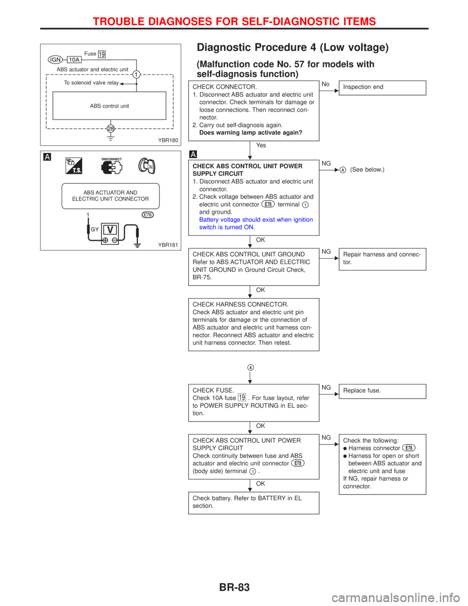
Diagnostic Procedure 4 (Low voltage)
(Malfunction code No. 57 for models with
self-diagnosis function)
CHECK CONNECTOR.
1. Disconnect ABS actuator and electric unit
connector. Check terminals for damage or
loose connections. Then reconnect con-
nector.
2. Carry out self-diagnosis again.
Does warning lamp activate again?
Ye s
ENo
Inspection end
CHECK ABS CONTROL UNIT POWER
SUPPLY CIRCUIT
1. Disconnect ABS actuator and electric unit
connector.
2. Check voltage between ABS actuator and
electric unit connector
E78terminalp1and ground.
Battery voltage should exist when ignition
switch is turned ON.
OK
ENGpA(See below.)
CHECK ABS CONTROL UNIT GROUND
Refer to ABS ACTUATOR AND ELECTRIC
UNIT GROUND in Ground Circuit Check,
BR-75.
OK
ENG
Repair harness and connec-
tor.
CHECK HARNESS CONNECTOR.
Check ABS actuator and electric unit pin
terminals for damage or the connection of
ABS actuator and electric unit harness con-
nector. Reconnect ABS actuator and electric
unit harness connector. Then retest.
pA
CHECK FUSE.
Check 10A fuse19. For fuse layout, refer
to POWER SUPPLY ROUTING in EL sec-
tion.
OK
ENG
Replace fuse.
CHECK ABS CONTROL UNIT POWER
SUPPLY CIRCUIT
Check continuity between fuse and ABS
actuator and electric unit connector
E78
(body side) terminalp1.
OK
ENG
Check the following:
lHarness connectorE78
lHarness for open or short
between ABS actuator and
electric unit and fuse
If NG, repair harness or
connector.
Check battery. Refer to BATTERY in EL
section.
YBR180 ABS control unit To solenoid valve relay ABS actuator and electric unit
.Fuse
YBR181
ABS ACTUATOR AND
ELECTRIC UNIT CONNECTOR
H
H
H
H
H
H
TROUBLE DIAGNOSES FOR SELF-DIAGNOSTIC ITEMS
BR-83
Page 210 of 2267
lApplying brake gradually when shifting or operating clutch.
lLow friction (slippery) road.
lHigh speed concerning.
lDriving over bumps and pot holes.
lEngine speed is over 5,000 rpm with vehicle stopped.
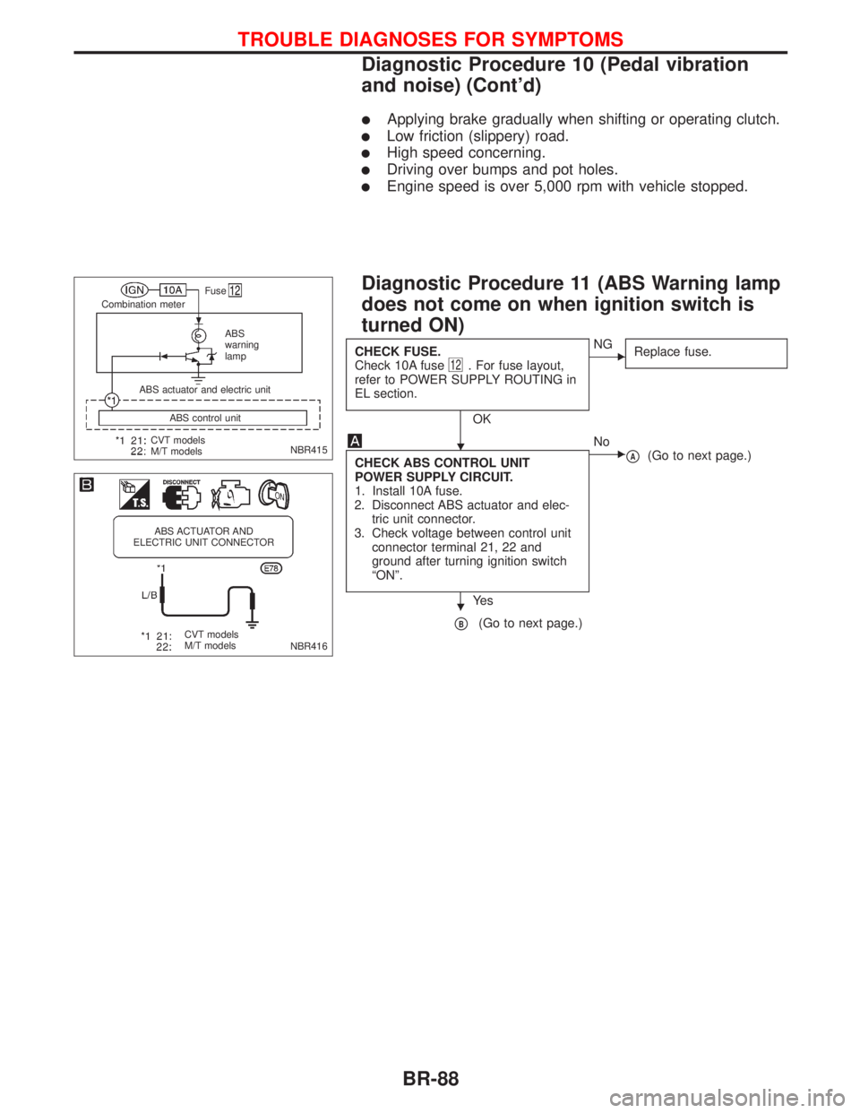
Diagnostic Procedure 11 (ABS Warning lamp
does not come on when ignition switch is
turned ON)
CHECK FUSE.
Check 10A fuse12. For fuse layout,
refer to POWER SUPPLY ROUTING in
EL section.
OK
ENG
Replace fuse.
CHECK ABS CONTROL UNIT
POWER SUPPLY CIRCUIT.
1. Install 10A fuse.
2. Disconnect ABS actuator and elec-
tric unit connector.
3. Check voltage between control unit
connector terminal 21, 22 and
ground after turning ignition switch
ªONº.
Ye s
ENo
pA(Go to next page.)
pB(Go to next page.)
NBR415
.Fuse
Combination meter
ABS
warning
lamp
CVT models
M/T modelsABS control unit ABS actuator and electric unit
NBR416
ABS ACTUATOR AND
ELECTRIC UNIT CONNECTOR
CVT models
M/T models
H
H
TROUBLE DIAGNOSES FOR SYMPTOMS
Diagnostic Procedure 10 (Pedal vibration
and noise) (Cont'd)
BR-88
Page 211 of 2267
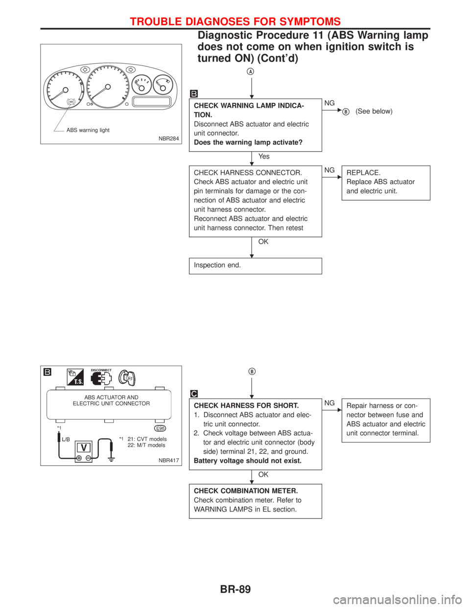
pA
CHECK WARNING LAMP INDICA-
TION.
Disconnect ABS actuator and electric
unit connector.
Does the warning lamp activate?
Ye s
ENG
pB(See below)
CHECK HARNESS CONNECTOR.
Check ABS actuator and electric unit
pin terminals for damage or the con-
nection of ABS actuator and electric
unit harness connector.
Reconnect ABS actuator and electric
unit harness connector. Then retest
OK
ENG
REPLACE.
Replace ABS actuator
and electric unit.
Inspection end.
pB
CHECK HARNESS FOR SHORT.
1. Disconnect ABS actuator and elec-
tric unit connector.
2. Check voltage between ABS actua-
tor and electric unit connector (body
side) terminal 21, 22, and ground.
Battery voltage should not exist.
OK
ENG
Repair harness or con-
nector between fuse and
ABS actuator and electric
unit connector terminal.
CHECK COMBINATION METER.
Check combination meter. Refer to
WARNING LAMPS in EL section.
NBR284 ABS warning light
NBR417
ABS ACTUATOR AND
ELECTRIC UNIT CONNECTOR
.21: CVT models
22: M/T models
H
H
H
H
H
TROUBLE DIAGNOSES FOR SYMPTOMS
Diagnostic Procedure 11 (ABS Warning lamp
does not come on when ignition switch is
turned ON) (Cont'd)
BR-89
Page 212 of 2267
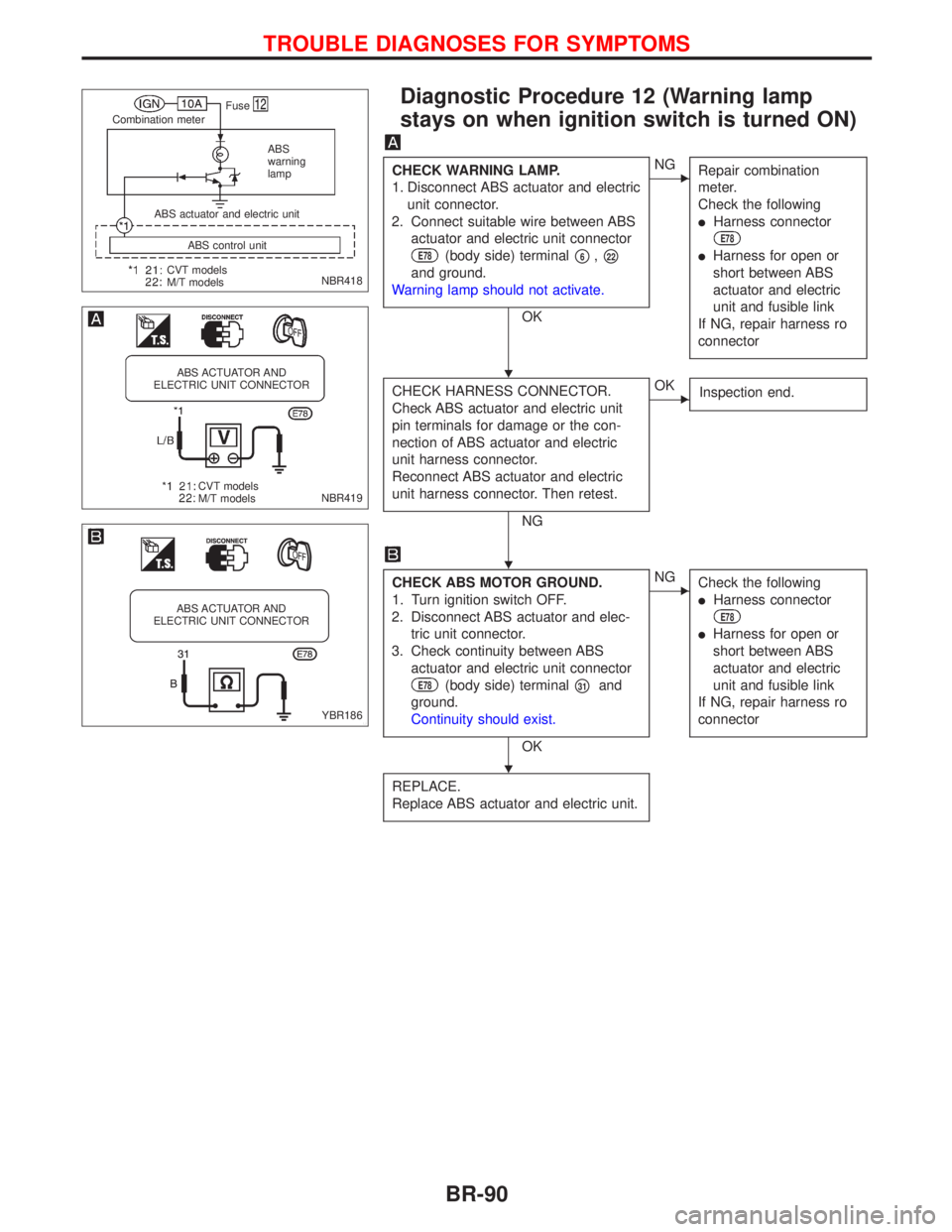
Diagnostic Procedure 12 (Warning lamp
stays on when ignition switch is turned ON)
CHECK WARNING LAMP.
1. Disconnect ABS actuator and electric
unit connector.
2. Connect suitable wire between ABS
actuator and electric unit connector
E78(body side) terminalp6,p22
and ground.
Warning lamp should not activate.
OK
ENG
Repair combination
meter.
Check the following
lHarness connector
E78
lHarness for open or
short between ABS
actuator and electric
unit and fusible link
If NG, repair harness ro
connector
CHECK HARNESS CONNECTOR.
Check ABS actuator and electric unit
pin terminals for damage or the con-
nection of ABS actuator and electric
unit harness connector.
Reconnect ABS actuator and electric
unit harness connector. Then retest.
NG
EOK
Inspection end.
CHECK ABS MOTOR GROUND.
1. Turn ignition switch OFF.
2. Disconnect ABS actuator and elec-
tric unit connector.
3. Check continuity between ABS
actuator and electric unit connector
E78(body side) terminalp31and
ground.
Continuity should exist.
OK
ENG
Check the following
lHarness connector
E78
lHarness for open or
short between ABS
actuator and electric
unit and fusible link
If NG, repair harness ro
connector
REPLACE.
Replace ABS actuator and electric unit.
NBR418
.Fuse
Combination meter
ABS
warning
lamp
CVT models
M/T modelsABS control unit ABS actuator and electric unit
NBR419
ABS ACTUATOR AND
ELECTRIC UNIT CONNECTOR
CVT models
M/T models
YBR186
ABS ACTUATOR AND
ELECTRIC UNIT CONNECTOR
H
H
H
TROUBLE DIAGNOSES FOR SYMPTOMS
BR-90