Page 1998 of 2267
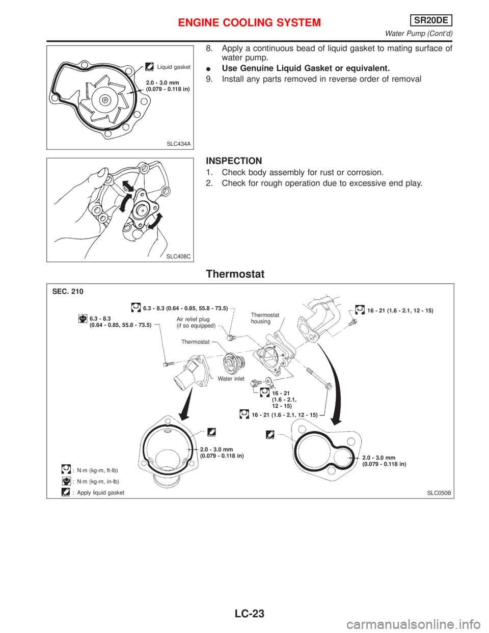
8. Apply a continuous bead of liquid gasket to mating surface of
water pump.
�Use Genuine Liquid Gasket or equivalent.
9. Install any parts removed in reverse order of removal
INSPECTION
1. Check body assembly for rust or corrosion.
2. Check for rough operation due to excessive end play.
Thermostat
SLC434A
Liquid gasket
2.0 - 3.0 mm
(0.079 - 0.118 in)
SLC408C
SLC050B
SEC. 210
6.3 - 8.3
(0.64 - 0.85, 55.8 - 73.5)
6.3 - 8.3 (0.64 - 0.85, 55.8 - 73.5)
Air relief plug
(if so equipped)Thermostat
housing16 - 21 (1.6 - 2.1, 12 - 15)
Water inlet
16 - 21
(1.6 - 2.1,
12 - 15)
16 - 21 (1.6 - 2.1, 12 - 15)
2.0 - 3.0 mm
(0.079 - 0.118 in)
2.0 - 3.0 mm
(0.079 - 0.118 in)
:N·m (kg-m, ft-lb)
:N·m (kg-m, in-lb)
: Apply liquid gasketThermostat
.
ENGINE COOLING SYSTEMSR20DE
Water Pump (Cont’d)
LC-23
Page 1999 of 2267
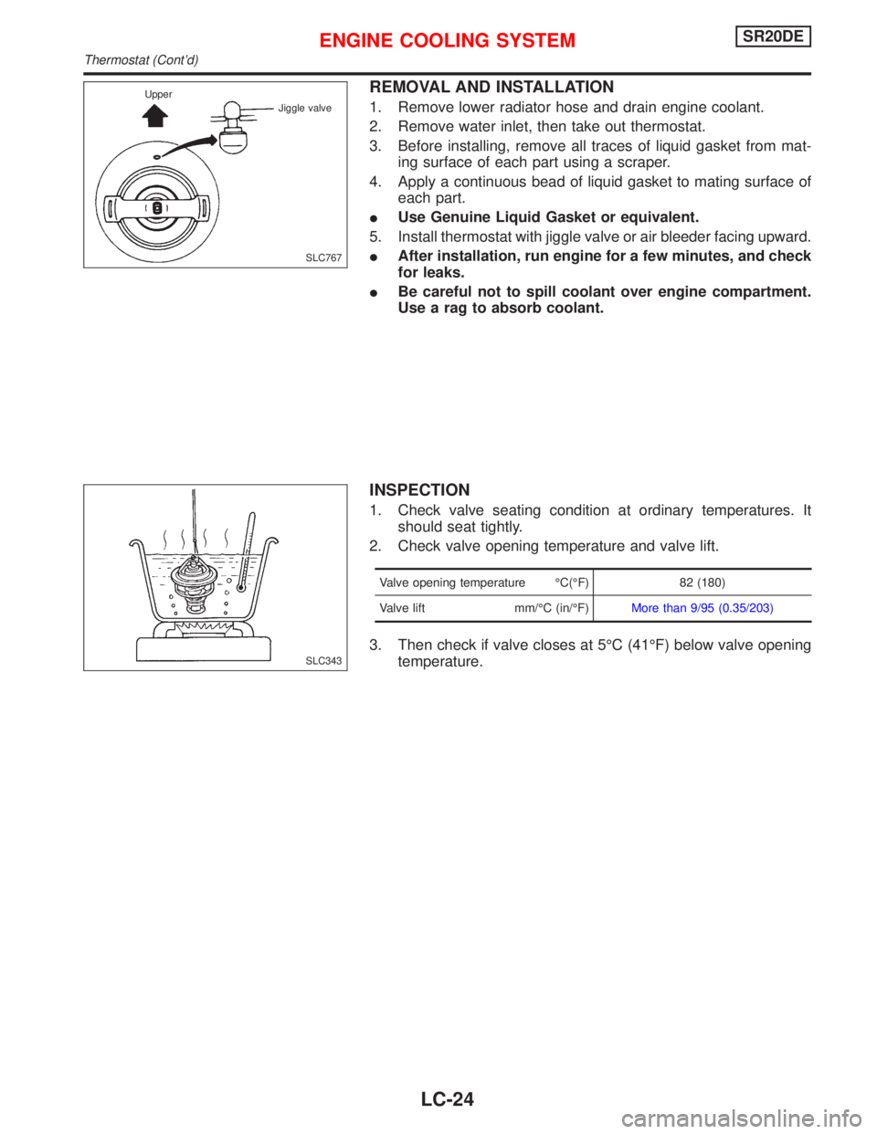
REMOVAL AND INSTALLATION
1. Remove lower radiator hose and drain engine coolant.
2. Remove water inlet, then take out thermostat.
3. Before installing, remove all traces of liquid gasket from mat-
ing surface of each part using a scraper.
4. Apply a continuous bead of liquid gasket to mating surface of
each part.
�Use Genuine Liquid Gasket or equivalent.
5. Install thermostat with jiggle valve or air bleeder facing upward.
�After installation, run engine for a few minutes, and check
for leaks.
�Be careful not to spill coolant over engine compartment.
Use a rag to absorb coolant.
INSPECTION
1. Check valve seating condition at ordinary temperatures. It
should seat tightly.
2. Check valve opening temperature and valve lift.
Valve opening temperature°C(°F) 82 (180)
Valve lift mm/°C (in/°F)More than 9/95 (0.35/203)
3. Then check if valve closes at 5°C (41°F) below valve opening
temperature.
SLC767 Upper
Jiggle valve
SLC343
ENGINE COOLING SYSTEMSR20DE
Thermostat (Cont’d)
LC-24
Page 2002 of 2267
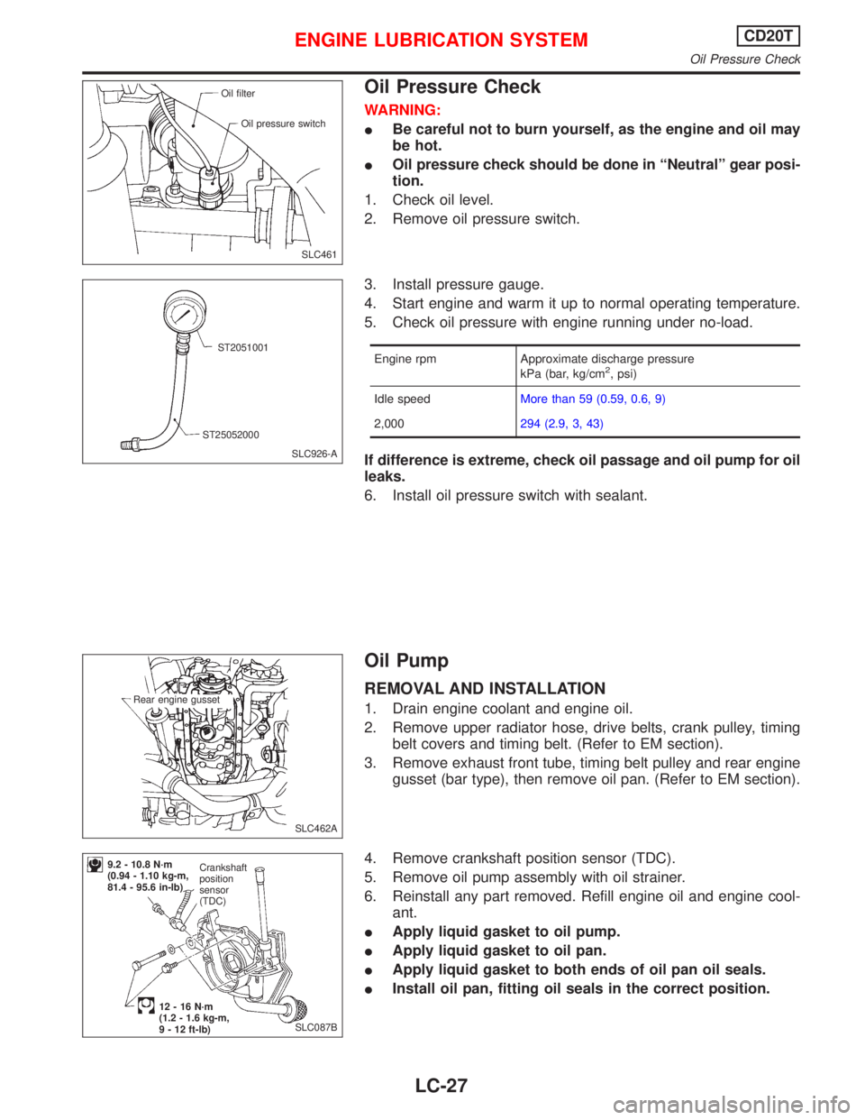
Oil Pressure Check
WARNING:
�Be careful not to burn yourself, as the engine and oil may
be hot.
�Oil pressure check should be done in“Neutral”gear posi-
tion.
1. Check oil level.
2. Remove oil pressure switch.
3. Install pressure gauge.
4. Start engine and warm it up to normal operating temperature.
5. Check oil pressure with engine running under no-load.
Engine rpm Approximate discharge pressure
kPa (bar, kg/cm2, psi)
Idle speedMore than 59 (0.59, 0.6, 9)
2,000294 (2.9, 3, 43)
If difference is extreme, check oil passage and oil pump for oil
leaks.
6. Install oil pressure switch with sealant.
Oil Pump
REMOVAL AND INSTALLATION
1. Drain engine coolant and engine oil.
2. Remove upper radiator hose, drive belts, crank pulley, timing
belt covers and timing belt. (Refer to EM section).
3. Remove exhaust front tube, timing belt pulley and rear engine
gusset (bar type), then remove oil pan. (Refer to EM section).
4. Remove crankshaft position sensor (TDC).
5. Remove oil pump assembly with oil strainer.
6. Reinstall any part removed. Refill engine oil and engine cool-
ant.
�Apply liquid gasket to oil pump.
�Apply liquid gasket to oil pan.
�Apply liquid gasket to both ends of oil pan oil seals.
�Install oil pan, fitting oil seals in the correct position.
SLC461
Oil filter
Oil pressure switch
SLC926-A ST2051001
ST25052000
SLC462A Rear engine gusset
SLC087B
9.2 - 10.8 N·m
(0.94 - 1.10 kg-m,
81.4 - 95.6 in-lb)Crankshaft
position
sensor
(TDC)
12 - 16 N·m
(1.2 - 1.6 kg-m,
9 - 12 ft-lb)
ENGINE LUBRICATION SYSTEMCD20T
Oil Pressure Check
LC-27
Page 2004 of 2267
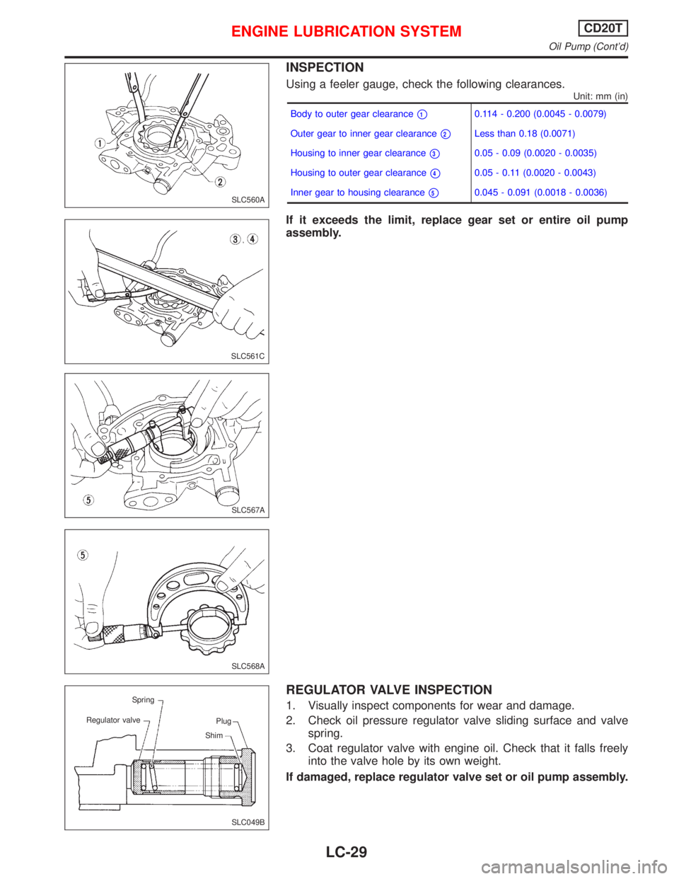
INSPECTION
Using a feeler gauge, check the following clearances.
Unit: mm (in)
Body to outer gear clearance�10.114 - 0.200 (0.0045 - 0.0079)
Outer gear to inner gear clearance
�2Less than 0.18 (0.0071)
Housing to inner gear clearance
�30.05 - 0.09 (0.0020 - 0.0035)
Housing to outer gear clearance
�40.05 - 0.11 (0.0020 - 0.0043)
Inner gear to housing clearance
�50.045 - 0.091 (0.0018 - 0.0036)
If it exceeds the limit, replace gear set or entire oil pump
assembly.
REGULATOR VALVE INSPECTION
1. Visually inspect components for wear and damage.
2. Check oil pressure regulator valve sliding surface and valve
spring.
3. Coat regulator valve with engine oil. Check that it falls freely
into the valve hole by its own weight.
If damaged, replace regulator valve set or oil pump assembly.
SLC560A
SLC561C
SLC567A
SLC568A
SLC049B Spring
Regulator valve
Plug
Shim
ENGINE LUBRICATION SYSTEMCD20T
Oil Pump (Cont’d)
LC-29
Page 2005 of 2267
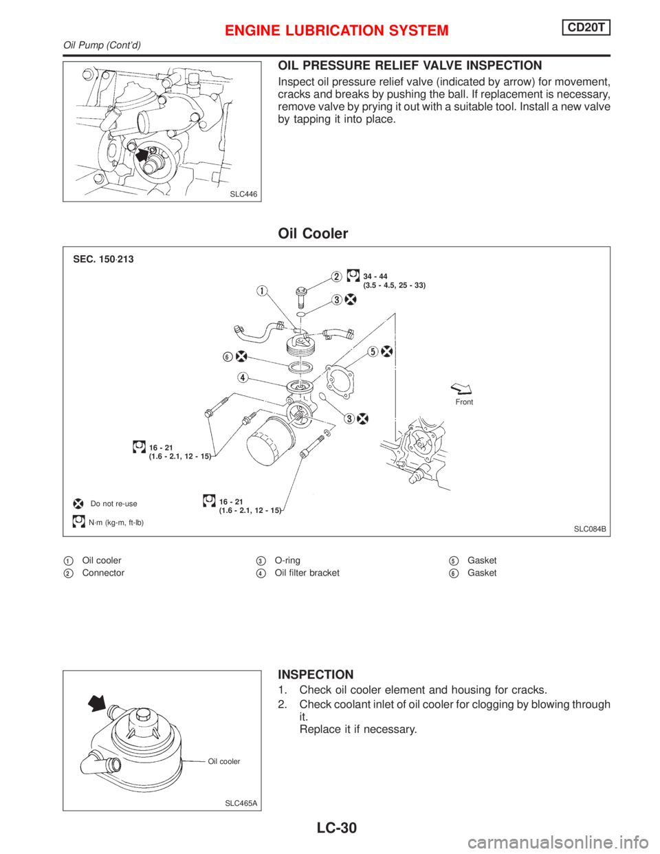
OIL PRESSURE RELIEF VALVE INSPECTION
Inspect oil pressure relief valve (indicated by arrow) for movement,
cracks and breaks by pushing the ball. If replacement is necessary,
remove valve by prying it out with a suitable tool. Install a new valve
by tapping it into place.
Oil Cooler
�1Oil cooler
�2Connector�3O-ring
�4Oil filter bracket�5Gasket
�6Gasket
INSPECTION
1. Check oil cooler element and housing for cracks.
2. Check coolant inlet of oil cooler for clogging by blowing through
it.
Replace it if necessary.
SLC446
SLC084B
34 - 44
(3.5 - 4.5, 25 - 33)
16 - 21
(1.6 - 2.1, 12 - 15)
16 - 21
(1.6 - 2.1, 12 - 15)Front
N·m (kg-m, ft-lb)
Do not re-use
.
�6
SEC. 150⋅213
SLC465A Oil cooler
ENGINE LUBRICATION SYSTEMCD20T
Oil Pump (Cont’d)
LC-30
Page 2007 of 2267
System Check
WARNING:
Never remove the radiator cap when the engine is hot; serious
burns could be caused by high pressure fluid escaping from
the radiator.
Wrap a thick cloth around cap and carefully loosen it a quar-
ter turn to release built-up pressure. Then remove the cap
completely.
CHECKING COOLING SYSTEM HOSES
Check hoses for improper attachment, leaks, cracks, damage,
loose connections, chafing and deterioration.
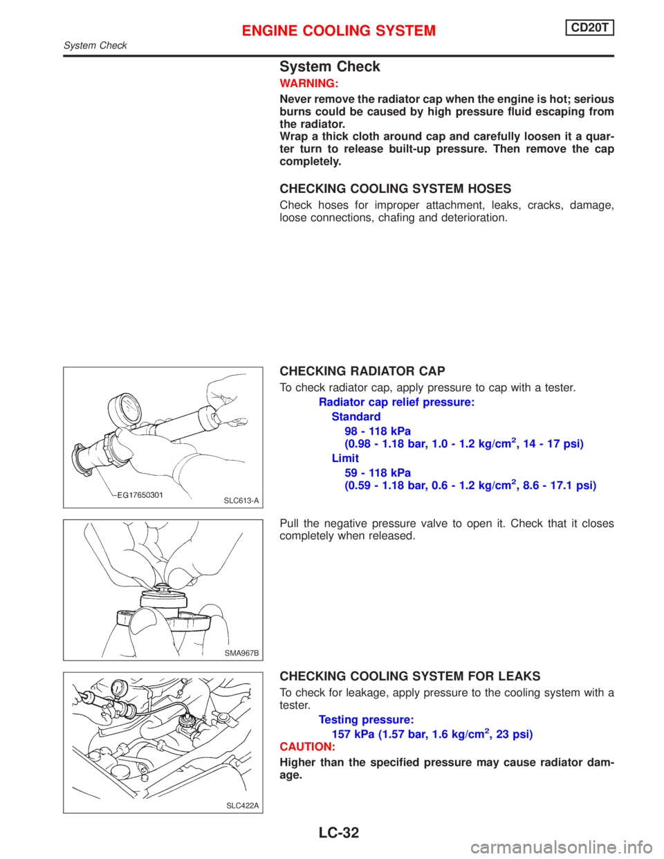
CHECKING RADIATOR CAP
To check radiator cap, apply pressure to cap with a tester.
Radiator cap relief pressure:
Standard
98 - 118 kPa
(0.98 - 1.18 bar, 1.0 - 1.2 kg/cm
2, 14 - 17 psi)
Limit
59 - 118 kPa
(0.59 - 1.18 bar, 0.6 - 1.2 kg/cm
2, 8.6 - 17.1 psi)
Pull the negative pressure valve to open it. Check that it closes
completely when released.
CHECKING COOLING SYSTEM FOR LEAKS
To check for leakage, apply pressure to the cooling system with a
tester.
Testing pressure:
157 kPa (1.57 bar, 1.6 kg/cm
2, 23 psi)
CAUTION:
Higher than the specified pressure may cause radiator dam-
age.
SLC613-A
SMA967B
SLC422A
ENGINE COOLING SYSTEMCD20T
System Check
LC-32
Page 2008 of 2267
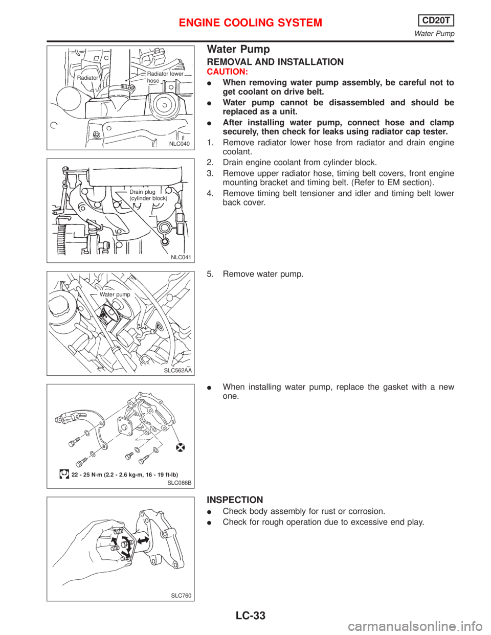
Water Pump
REMOVAL AND INSTALLATION
CAUTION:
�When removing water pump assembly, be careful not to
get coolant on drive belt.
�Water pump cannot be disassembled and should be
replaced as a unit.
�After installing water pump, connect hose and clamp
securely, then check for leaks using radiator cap tester.
1. Remove radiator lower hose from radiator and drain engine
coolant.
2. Drain engine coolant from cylinder block.
3. Remove upper radiator hose, timing belt covers, front engine
mounting bracket and timing belt. (Refer to EM section).
4. Remove timing belt tensioner and idler and timing belt lower
back cover.
5. Remove water pump.
�When installing water pump, replace the gasket with a new
one.
INSPECTION
�Check body assembly for rust or corrosion.
�Check for rough operation due to excessive end play.
.NLC040
.Radiator
.Radiator lower.hose
NLC041 Drain plug
(cylinder block)
.SLC562AA Water pump
SLC086B
22 - 25 N·m (2.2 - 2.6 kg-m, 16 - 19 ft-lb)
SLC760
ENGINE COOLING SYSTEMCD20T
Water Pump
LC-33
Page 2009 of 2267
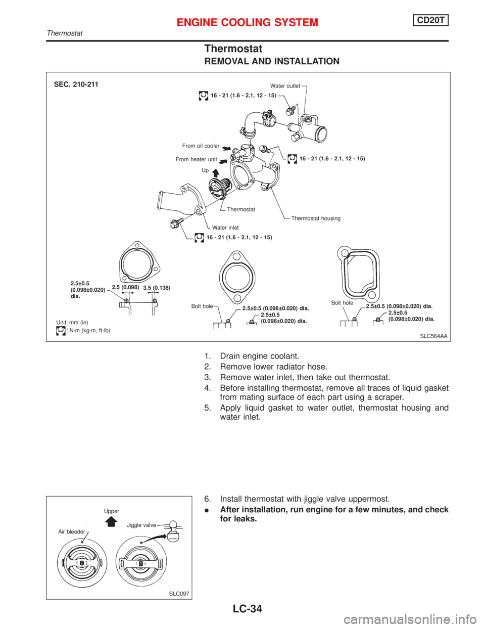
Thermostat
REMOVAL AND INSTALLATION
1. Drain engine coolant.
2. Remove lower radiator hose.
3. Remove water inlet, then take out thermostat.
4. Before installing thermostat, remove all traces of liquid gasket
from mating surface of each part using a scraper.
5. Apply liquid gasket to water outlet, thermostat housing and
water inlet.
6. Install thermostat with jiggle valve uppermost.
�After installation, run engine for a few minutes, and check
for leaks.
SLC564AA
SEC. 210-211Water outlet
16 - 21 (1.6 - 2.1, 12 - 15)
From oil cooler
From heater unit
16 - 21 (1.6 - 2.1, 12 - 15)
Up
Thermostat
Thermostat housing
Water inlet
16 - 21 (1.6 - 2.1, 12 - 15)
2.5±0.5
(0.098±0.020)
dia.2.5 (0.098)
3.5 (0.138)
Bolt hole
2.5±0.5 (0.098±0.020) dia.
2.5±0.5
(0.098±0.020) dia.Bolt hole
2.5±0.5 (0.098±0.020) dia.
2.5±0.5
(0.098±0.020) dia.
Unit: mm (in)
:N·m (kg-m, ft-lb)
SLC097 Air bleederUpper
Jiggle valve
ENGINE COOLING SYSTEMCD20T
Thermostat
LC-34