Page 1986 of 2267
INSPECTIONNCLC0019
�Check body assembly and vane for rust or corrosion.
�Check for rough operation due to excessive end play.
Thermostat
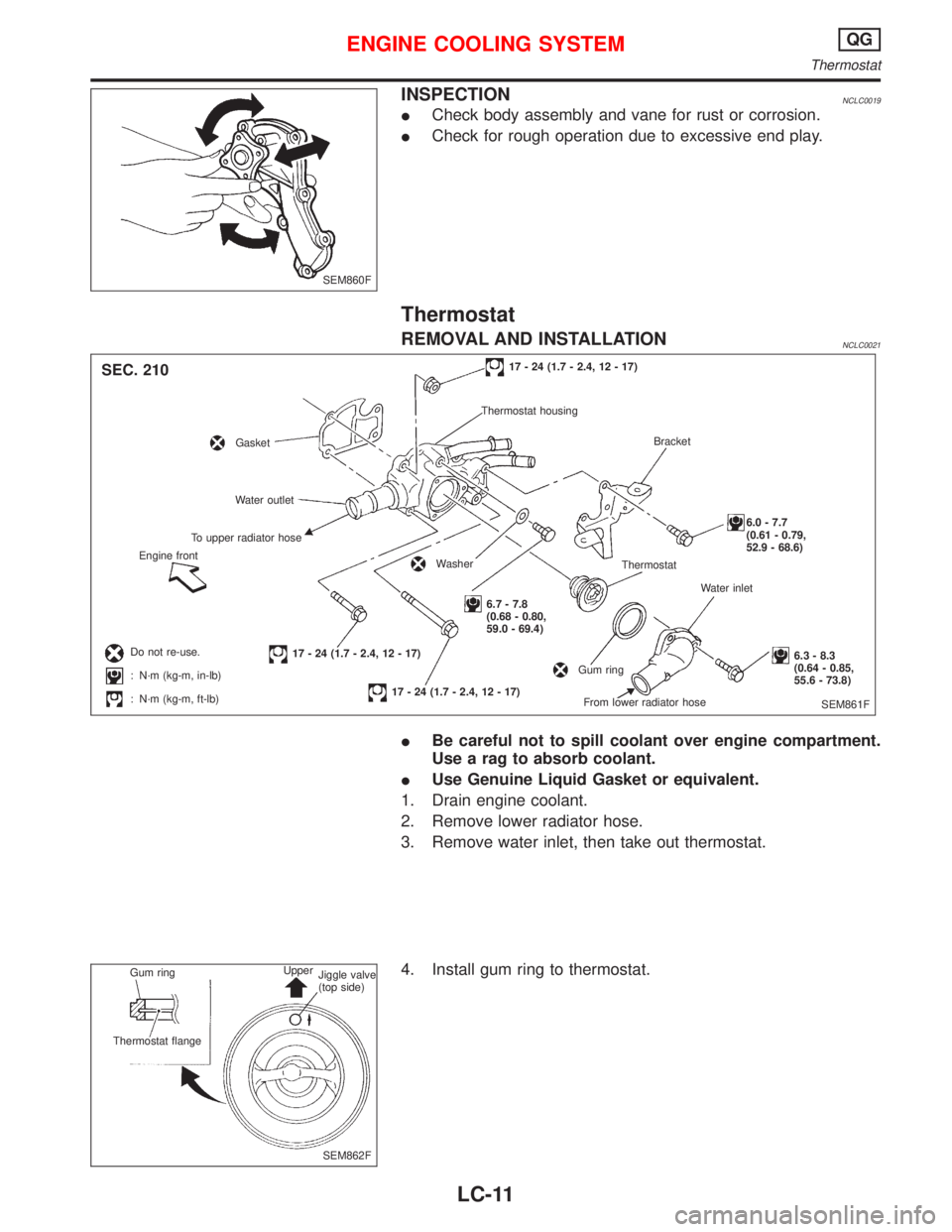
REMOVAL AND INSTALLATIONNCLC0021
�Be careful not to spill coolant over engine compartment.
Use a rag to absorb coolant.
�Use Genuine Liquid Gasket or equivalent.
1. Drain engine coolant.
2. Remove lower radiator hose.
3. Remove water inlet, then take out thermostat.
4. Install gum ring to thermostat.
SEM860F
SEM861F
17 - 24 (1.7 - 2.4, 12 - 17)
Thermostat housing
Bracket
6.0 - 7.7
(0.61 - 0.79,
52.9 - 68.6)
Water inlet
6.3 - 8.3
(0.64 - 0.85,
55.6 - 73.8) Thermostat
From lower radiator hoseGum ring
6.7 - 7.8
(0.68 - 0.80,
59.0 - 69.4)
Washer
17 - 24 (1.7 - 2.4, 12 - 17)
17 - 24 (1.7 - 2.4, 12 - 17) Do not re-use.
:N·m (kg-m, in-lb)
:N·m (kg-m, ft-lb) Engine frontTo upper radiator hoseWater outlet
Gasket
SEC. 210
SEM862F Gum ring
Thermostat flangeUpper
Jiggle valve
(top side)
ENGINE COOLING SYSTEMQG
Thermostat
LC-11
Page 1987 of 2267
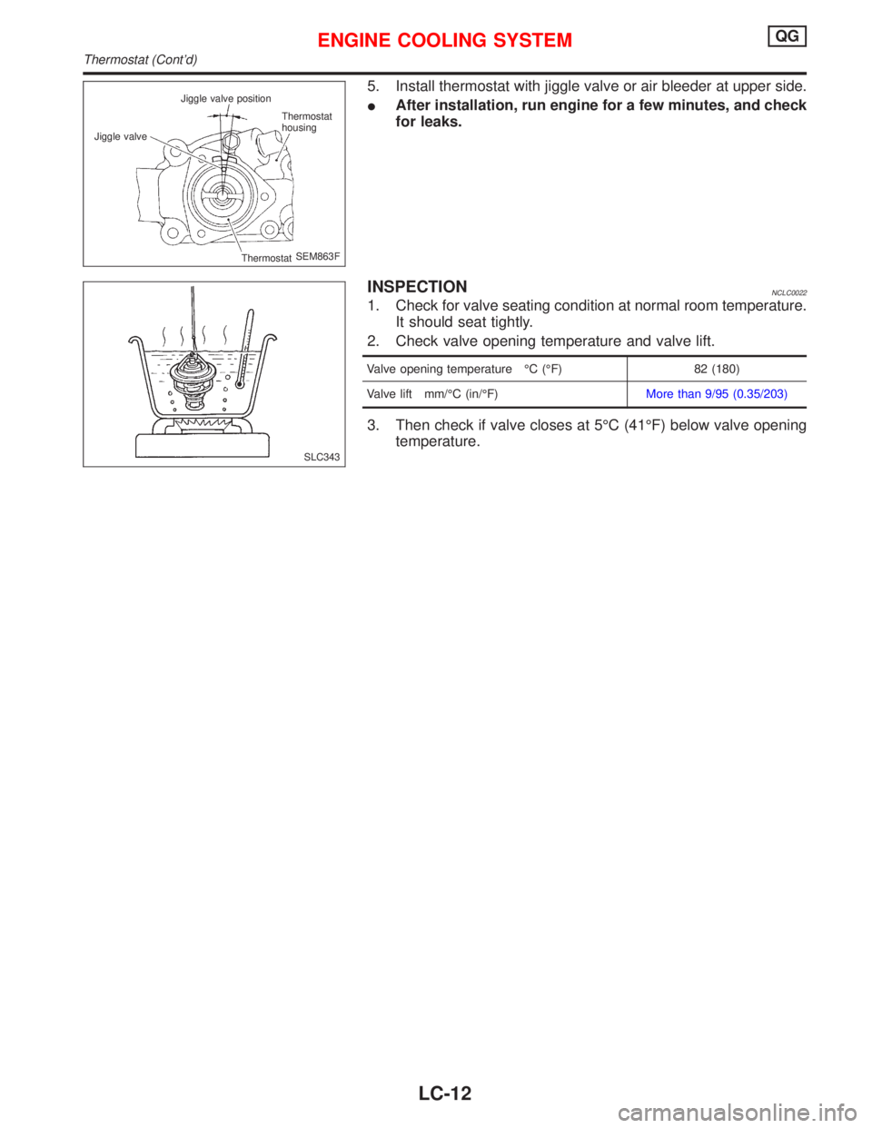
5. Install thermostat with jiggle valve or air bleeder at upper side.
�After installation, run engine for a few minutes, and check
for leaks.
INSPECTIONNCLC0022
1. Check for valve seating condition at normal room temperature.
It should seat tightly.
2. Check valve opening temperature and valve lift.
Valve opening temperature°C(°F) 82 (180)
Valve lift mm/°C (in/°F)More than 9/95 (0.35/203)
3. Then check if valve closes at 5°C (41°F) below valve opening
temperature.
SEM863F Jiggle valveJiggle valve position
Thermostat
housing
Thermostat
SLC343
ENGINE COOLING SYSTEMQG
Thermostat (Cont’d)
LC-12
Page 1991 of 2267
Oil Pressure Check
WARNING:
�Be careful not to burn yourself, as the engine and oil may
be hot.
�Oil pressure check should be done in“Neutral position”.
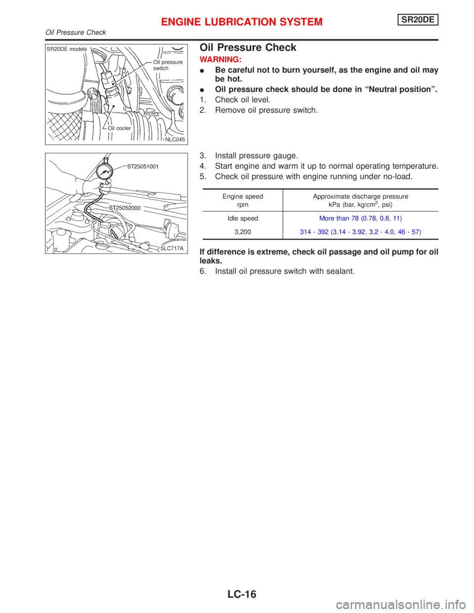
1. Check oil level.
2. Remove oil pressure switch.
3. Install pressure gauge.
4. Start engine and warm it up to normal operating temperature.
5. Check oil pressure with engine running under no-load.
Engine speed
rpmApproximate discharge pressure
kPa (bar, kg/cm2, psi)
Idle speedMore than 78 (0.78, 0.8, 11)
3,200314 - 392 (3.14 - 3.92, 3.2 - 4.0, 46 - 57)
If difference is extreme, check oil passage and oil pump for oil
leaks.
6. Install oil pressure switch with sealant.
.Oil pressure
switch
.Oil cooler.NLC045
.SR20DE models
.SLC717A
ENGINE LUBRICATION SYSTEMSR20DE
Oil Pressure Check
LC-16
Page 1993 of 2267
INSPECTION
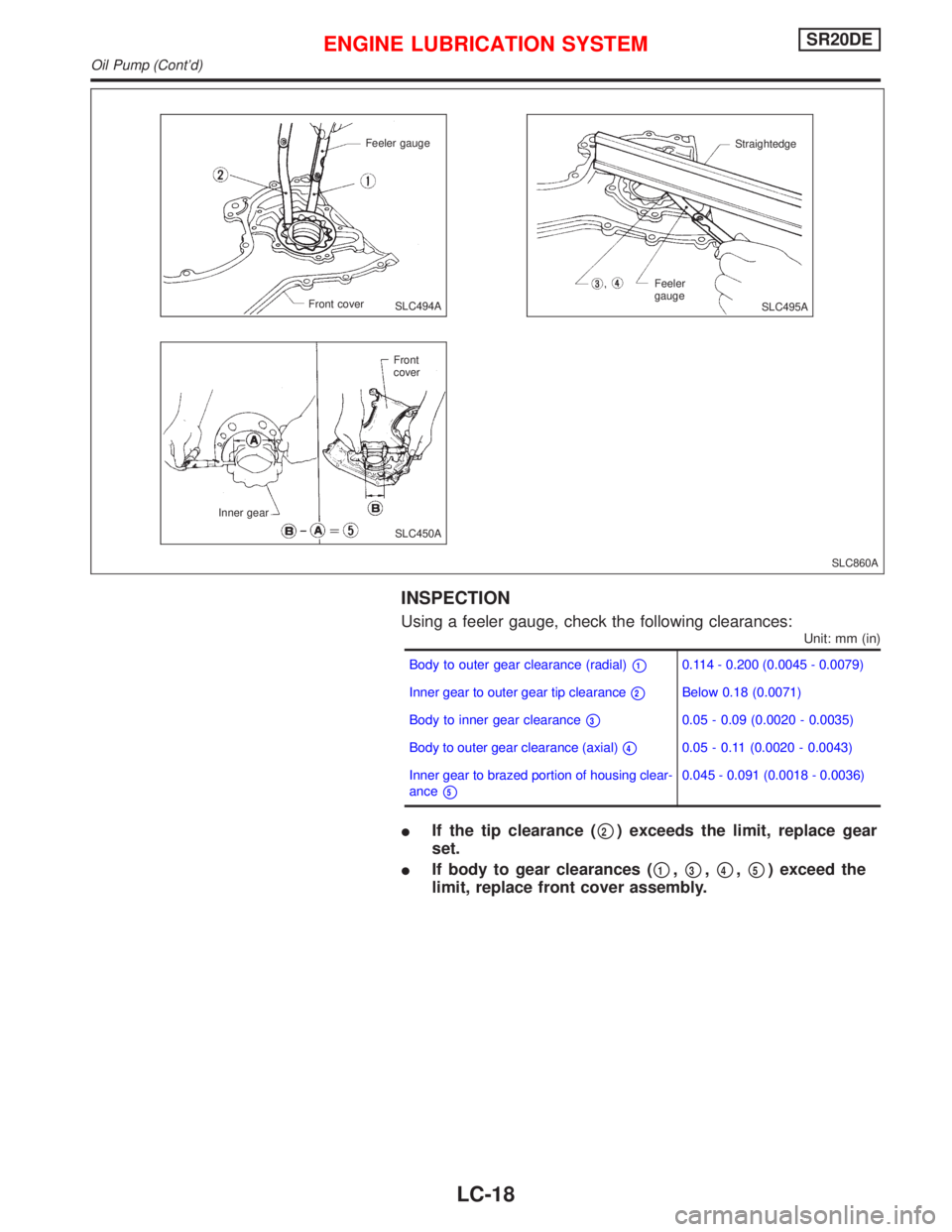
Using a feeler gauge, check the following clearances:
Unit: mm (in)
Body to outer gear clearance (radial)�10.114 - 0.200 (0.0045 - 0.0079)
Inner gear to outer gear tip clearance
�2Below 0.18 (0.0071)
Body to inner gear clearance
�30.05 - 0.09 (0.0020 - 0.0035)
Body to outer gear clearance (axial)
�40.05 - 0.11 (0.0020 - 0.0043)
Inner gear to brazed portion of housing clear-
ance
�5
0.045 - 0.091 (0.0018 - 0.0036)
�If the tip clearance (�2) exceeds the limit, replace gear
set.
�If body to gear clearances (
�1,�3,�4,�5) exceed the
limit, replace front cover assembly.
SLC860A
Feeler gauge
Front cover
Front
cover
Inner gearStraightedge
Feeler
gauge
SLC494A
SLC495A
SLC450A
ENGINE LUBRICATION SYSTEMSR20DE
Oil Pump (Cont’d)
LC-18
Page 1994 of 2267
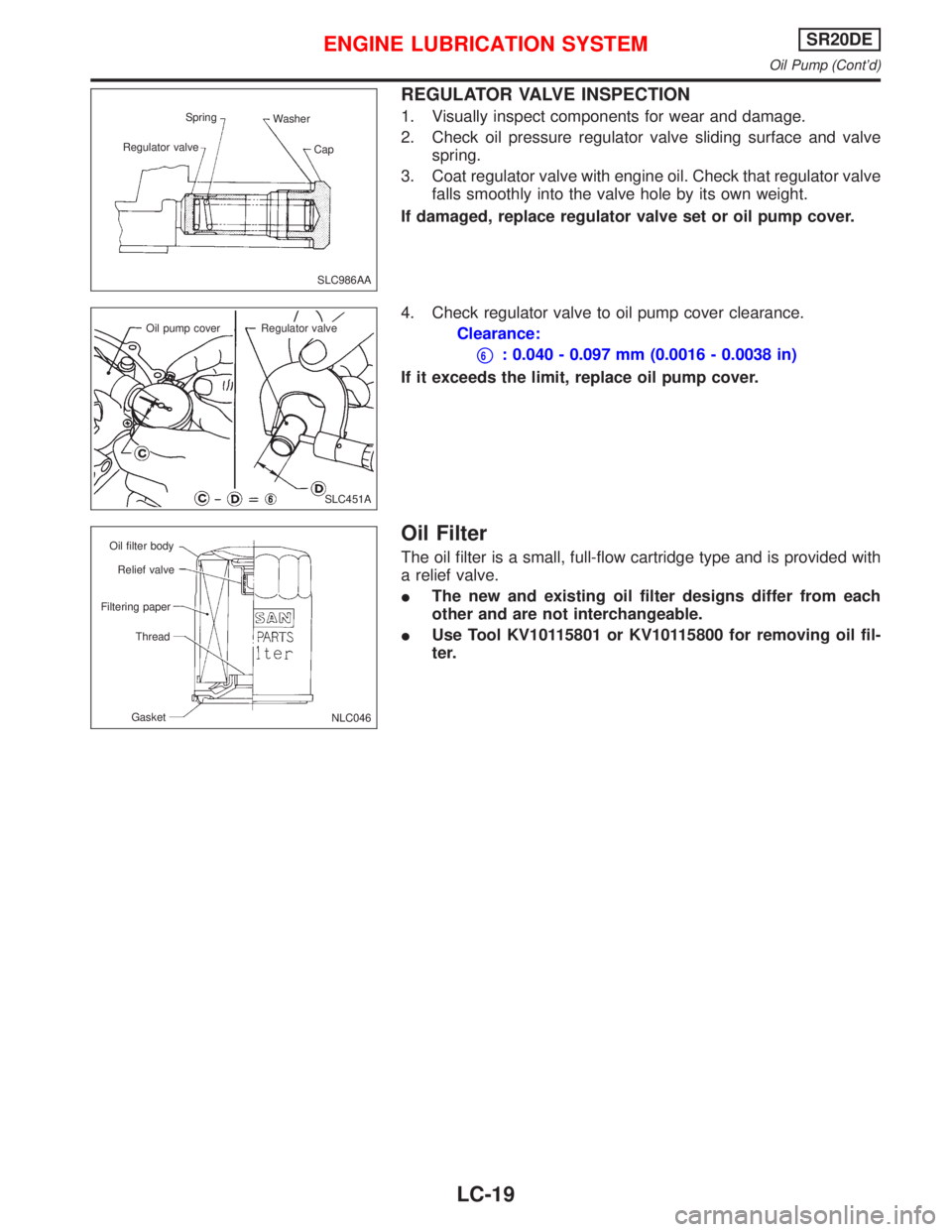
REGULATOR VALVE INSPECTION
1. Visually inspect components for wear and damage.
2. Check oil pressure regulator valve sliding surface and valve
spring.
3. Coat regulator valve with engine oil. Check that regulator valve
falls smoothly into the valve hole by its own weight.
If damaged, replace regulator valve set or oil pump cover.
4. Check regulator valve to oil pump cover clearance.
Clearance:
�6: 0.040 - 0.097 mm (0.0016 - 0.0038 in)
If it exceeds the limit, replace oil pump cover.
Oil Filter
The oil filter is a small, full-flow cartridge type and is provided with
a relief valve.
�The new and existing oil filter designs differ from each
other and are not interchangeable.
�Use Tool KV10115801 or KV10115800 for removing oil fil-
ter.
SLC986AA Spring
Regulator valveWasher
Cap
SLC451A Oil pump cover
Regulator valve
NLC046 Oil filter body
Relief valve
Filtering paper
Thread
Gasket
ENGINE LUBRICATION SYSTEMSR20DE
Oil Pump (Cont’d)
LC-19
Page 1995 of 2267
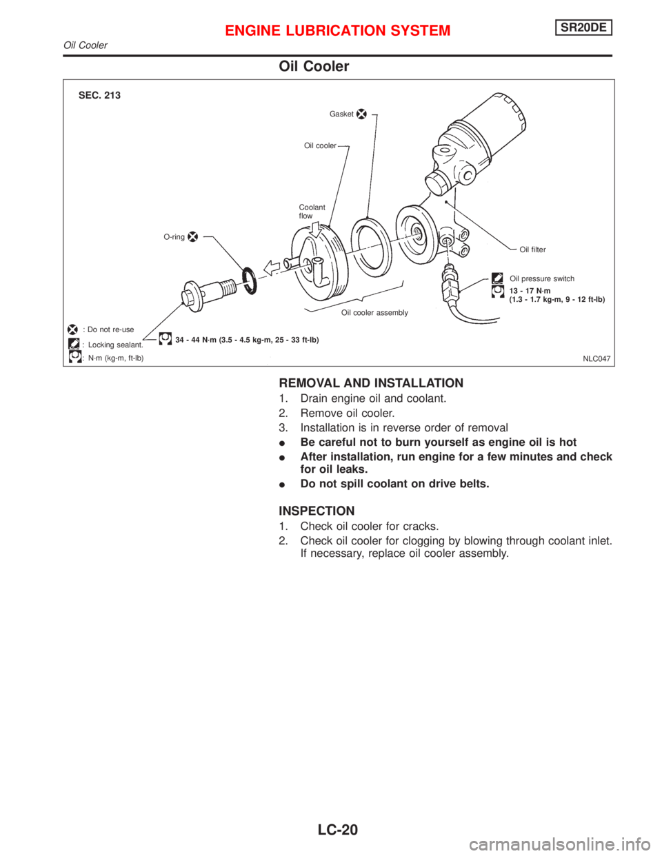
Oil Cooler
REMOVAL AND INSTALLATION
1. Drain engine oil and coolant.
2. Remove oil cooler.
3. Installation is in reverse order of removal
�Be careful not to burn yourself as engine oil is hot
�After installation, run engine for a few minutes and check
for oil leaks.
�Do not spill coolant on drive belts.
INSPECTION
1. Check oil cooler for cracks.
2. Check oil cooler for clogging by blowing through coolant inlet.
If necessary, replace oil cooler assembly.
NLC047 Gasket
Oil cooler
Coolant
flow
O-ring
34 - 44 N·m (3.5 - 4.5 kg-m, 25 - 33 ft-lb)Oil cooler assemblyOil filter
Oil pressure switch
13 - 17 N·m
(1.3 - 1.7 kg-m, 9 - 12 ft-lb)
SEC. 213
: Locking sealant.
:N·m (kg-m, ft-lb)
: Do not re-use
.
ENGINE LUBRICATION SYSTEMSR20DE
Oil Cooler
LC-20
Page 1996 of 2267
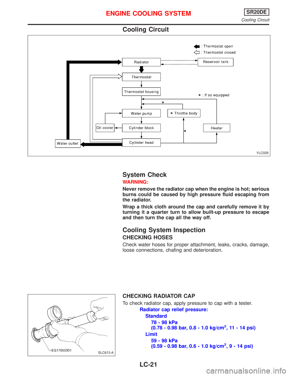
Cooling Circuit
System Check
WARNING:
Never remove the radiator cap when the engine is hot; serious
burns could be caused by high pressure fluid escaping from
the radiator.
Wrap a thick cloth around the cap and carefully remove it by
turning it a quarter turn to allow built-up pressure to escape
and then turn the cap all the way off.
Cooling System Inspection
CHECKING HOSES
Check water hoses for proper attachment, leaks, cracks, damage,
loose connections, chafing and deterioration.
CHECKING RADIATOR CAP
To check radiator cap, apply pressure to cap with a tester.
Radiator cap relief pressure:
Standard
78-98kPa
(0.78 - 0.98 bar, 0.8 - 1.0 kg/cm
2, 11 - 14 psi)
Limit
59-98kPa
(0.59 - 0.98 bar, 0.6 - 1.0 kg/cm
2,9-14psi)
YLC029
SLC613-A
ENGINE COOLING SYSTEMSR20DE
Cooling Circuit
LC-21
Page 1997 of 2267
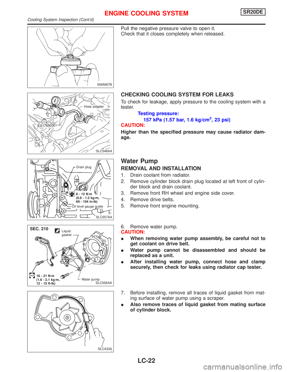
Pull the negative pressure valve to open it.
Check that it closes completely when released.
CHECKING COOLING SYSTEM FOR LEAKS
To check for leakage, apply pressure to the cooling system with a
tester.
Testing pressure:
157 kPa (1.57 bar, 1.6 kg/cm
2, 23 psi)
CAUTION:
Higher than the specified pressure may cause radiator dam-
age.
Water Pump
REMOVAL AND INSTALLATION
1. Drain coolant from radiator.
2. Remove cylinder block drain plug located at left front of cylin-
der block and drain coolant.
3. Remove front RH wheel and engine side cover.
4. Remove drive belts.
5. Remove front engine mounting.
6. Remove water pump.
CAUTION:
�When removing water pump assembly, be careful not to
get coolant on drive belt.
�Water pump cannot be disassembled and should be
replaced as a unit.
�After installing water pump, connect hose and clamp
securely, then check for leaks using radiator cap tester.
7. Before installing, remove all traces of liquid gasket from mat-
ing surface of water pump using a scraper.
�Also remove traces of liquid gasket from mating surface
of cylinder block.
SMA967B
.SLC546AA Hose adapter
.SLC557AA Drain plug
8-12N·m
(0.8 - 1.2 kg-m,
69 - 104 in-lb)
Oil level gauge guide
SLC556AA
Liquid
gasket
Water pump
16 - 21 N·m
(1.6 - 2.1 kg-m,
12 - 15 ft-lb)
SEC. 210
SLC433A
ENGINE COOLING SYSTEMSR20DE
Cooling System Inspection (Cont’d)
LC-22