Page 2047 of 2267
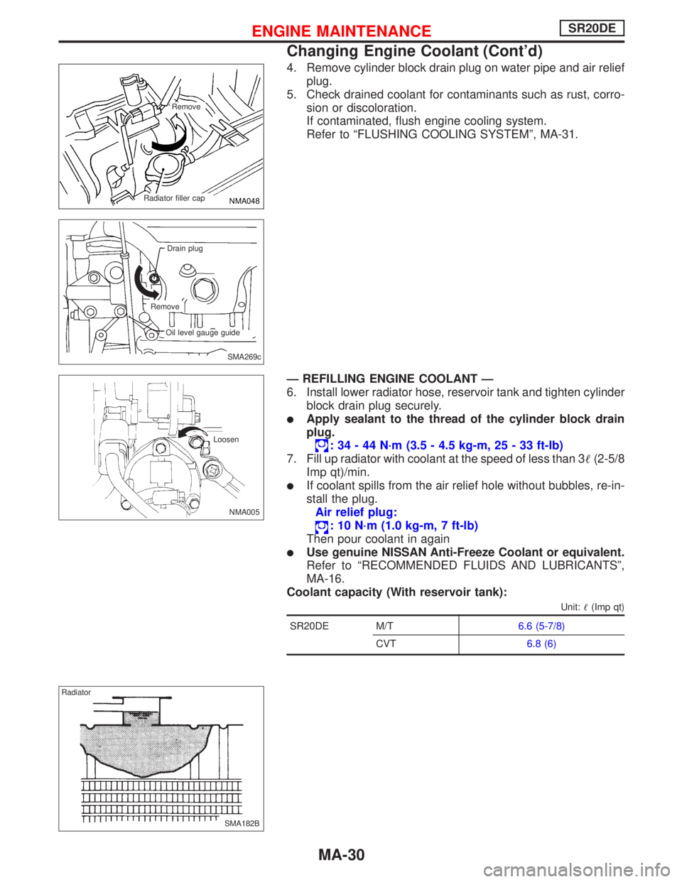
4. Remove cylinder block drain plug on water pipe and air relief
plug.
5. Check drained coolant for contaminants such as rust, corro-
sion or discoloration.
If contaminated, flush engine cooling system.
Refer to“FLUSHING COOLING SYSTEM”, MA-31.
—REFILLING ENGINE COOLANT—
6. Install lower radiator hose, reservoir tank and tighten cylinder
block drain plug securely.
�Apply sealant to the thread of the cylinder block drain
plug.
:34-44N·m (3.5 - 4.5 kg-m, 25 - 33 ft-lb)
7. Fill up radiator with coolant at the speed of less than 3�(2-5/8
Imp qt)/min.
�If coolant spills from the air relief hole without bubbles, re-in-
stall the plug.
Air relief plug:
:10N·m (1.0 kg-m, 7 ft-lb)
Then pour coolant in again
�Use genuine NISSAN Anti-Freeze Coolant or equivalent.
Refer to“RECOMMENDED FLUIDS AND LUBRICANTS”,
MA-16.
Coolant capacity (With reservoir tank):
Unit:�(Imp qt)
SR20DE M/T6.6 (5-7/8)
CVT6.8 (6)
NMA048
.Remove
.Radiator filler cap
.SMA269c Drain plug
Remove
Oil level gauge guide
NMA005 Loosen
SMA182B Radiator
ENGINE MAINTENANCESR20DE
Changing Engine Coolant (Cont’d)
MA-30
Page 2048 of 2267
8. Fill radiator and reservoir tank to specified level.
9. Start engine without installing radiator cap and warm it up at
2,000 rpm until radiator lower hose becomes hot.
�If coolant level becomes low, refill coolant until coolant level
does not change.
�If coolant overflows radiator filler hole, install filler cap.
10. Run engine at 2,500 prm for 10 seconds and return to idle
speed.
�Repeat 2 or 3 times.
Watch coolant temperature gauge so as not to overheat the
engine.
11. Stop engine and cool it down.
�Cool down using a fan to reduce the time.
�If necessary, refill radiator up to filler neck.
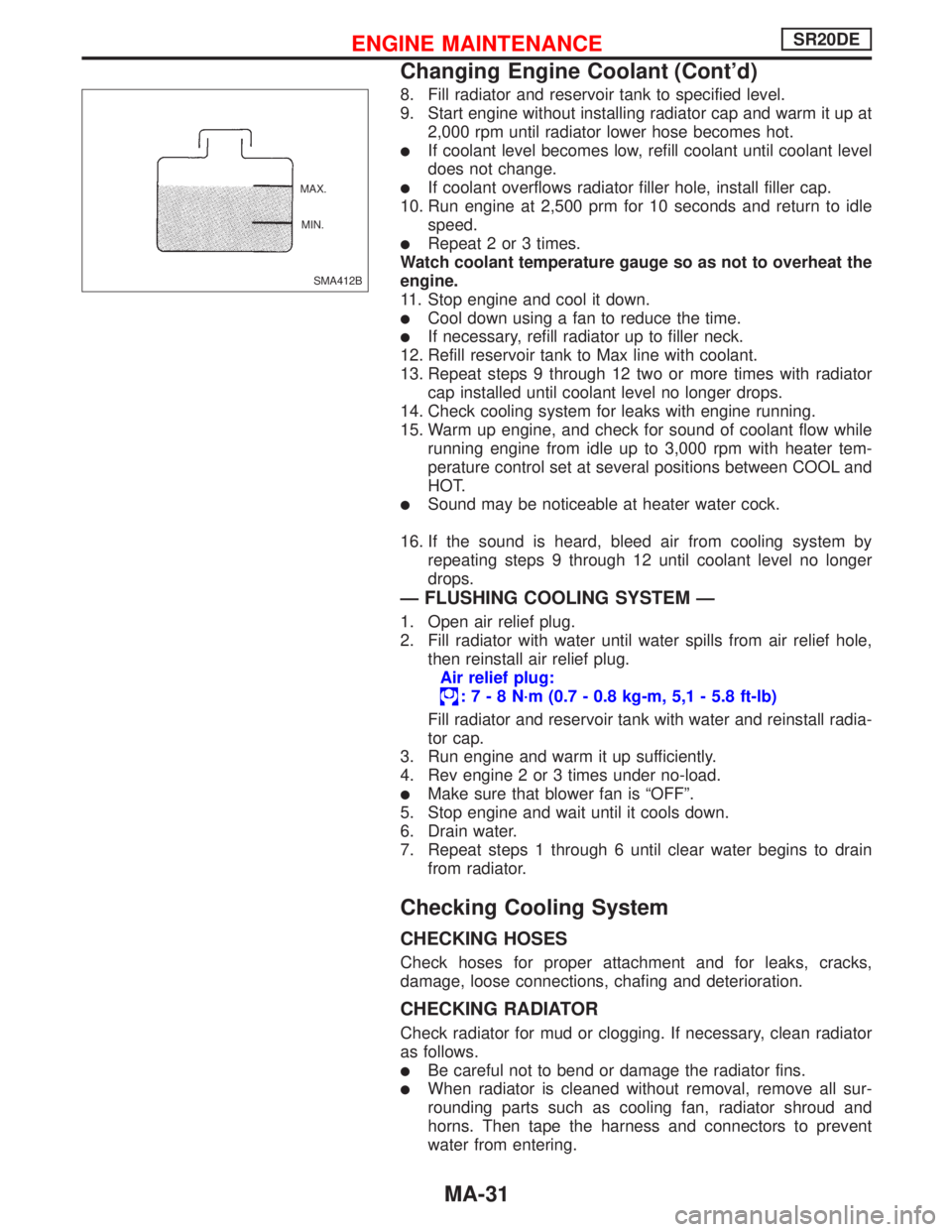
12. Refill reservoir tank to Max line with coolant.
13. Repeat steps 9 through 12 two or more times with radiator
cap installed until coolant level no longer drops.
14. Check cooling system for leaks with engine running.
15. Warm up engine, and check for sound of coolant flow while
running engine from idle up to 3,000 rpm with heater tem-
perature control set at several positions between COOL and
HOT.
�Sound may be noticeable at heater water cock.
16. If the sound is heard, bleed air from cooling system by
repeating steps 9 through 12 until coolant level no longer
drops.
—FLUSHING COOLING SYSTEM—
1. Open air relief plug.
2. Fill radiator with water until water spills from air relief hole,
then reinstall air relief plug.
Air relief plug:
:7-8N·m (0.7 - 0.8 kg-m, 5,1 - 5.8 ft-lb)
Fill radiator and reservoir tank with water and reinstall radia-
tor cap.
3. Run engine and warm it up sufficiently.
4. Rev engine 2 or 3 times under no-load.
�Make sure that blower fan is“OFF”.
5. Stop engine and wait until it cools down.
6. Drain water.
7. Repeat steps 1 through 6 until clear water begins to drain
from radiator.
Checking Cooling System
CHECKING HOSES
Check hoses for proper attachment and for leaks, cracks,
damage, loose connections, chafing and deterioration.
CHECKING RADIATOR
Check radiator for mud or clogging. If necessary, clean radiator
as follows.
�Be careful not to bend or damage the radiator fins.
�When radiator is cleaned without removal, remove all sur-
rounding parts such as cooling fan, radiator shroud and
horns. Then tape the harness and connectors to prevent
water from entering.
SMA412B MAX.
MIN.
ENGINE MAINTENANCESR20DE
Changing Engine Coolant (Cont’d)
MA-31
Page 2049 of 2267
1. Apply water by hose to the back side of the radiator core
vertically downward.
2. Apply water again to all radiator core surfaces once per
minute.
3. Stop washing if any stains no longer flow out from the radia-
tor.
4. Blow air into the back side of radiator core vertically down-
ward.
�Use compressed air lower than 5 kg/cm2and keep distance
more than 30 cm (11.8 in).
5. Blow air again into all the radiator core surfaces once per
minute until no water sprays out.
CHECKING RADIATOR CAP
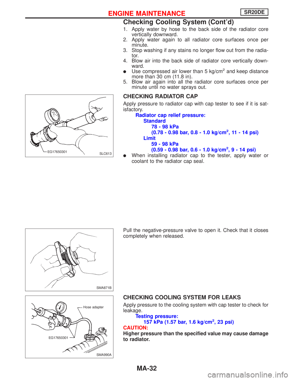
Apply pressure to radiator cap with cap tester to see if it is sat-
isfactory.
Radiator cap relief pressure:
Standard
78-98kPa
(0.78 - 0.98 bar, 0.8 - 1.0 kg/cm
2, 11 - 14 psi)
Limit
59-98kPa
(0.59 - 0.98 bar, 0.6 - 1.0 kg/cm
2,9-14psi)
�When installing radiator cap to the tester, apply water or
coolant to the radiator cap seal.
Pull the negative-pressure valve to open it. Check that it closes
completely when released.
CHECKING COOLING SYSTEM FOR LEAKS
Apply pressure to the cooling system with cap tester to check for
leakage.
Testing pressure:
157 kPa (1.57 bar, 1.6 kg/cm
2, 23 psi)
CAUTION:
Higher pressure than the specified value may cause damage
to radiator.
SLC613 EG17650301
SMA871B
SMA990A Hose adapter
EG17650301
ENGINE MAINTENANCESR20DE
Checking Cooling System (Cont’d)
MA-32
Page 2050 of 2267
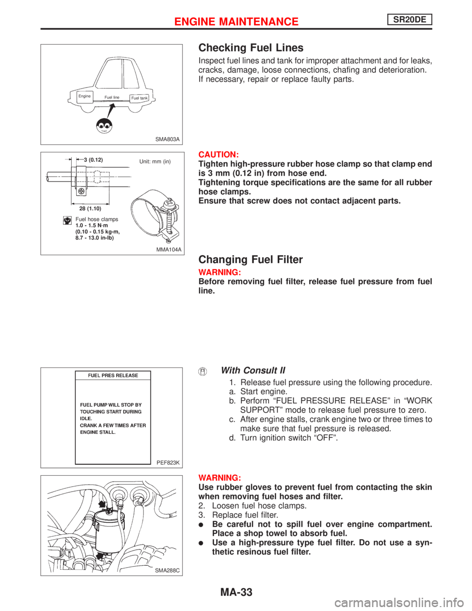
Checking Fuel Lines
Inspect fuel lines and tank for improper attachment and for leaks,
cracks, damage, loose connections, chafing and deterioration.
If necessary, repair or replace faulty parts.
CAUTION:
Tighten high-pressure rubber hose clamp so that clamp end
is 3 mm (0.12 in) from hose end.
Tightening torque specifications are the same for all rubber
hose clamps.
Ensure that screw does not contact adjacent parts.
Changing Fuel Filter
WARNING:
Before removing fuel filter, release fuel pressure from fuel
line.
With Consult II
1. Release fuel pressure using the following procedure.
a. Start engine.
b. Perform“FUEL PRESSURE RELEASE”in“WORK
SUPPORT”mode to release fuel pressure to zero.
c. After engine stalls, crank engine two or three times to
make sure that fuel pressure is released.
d. Turn ignition switch“OFF”.
WARNING:
Use rubber gloves to prevent fuel from contacting the skin
when removing fuel hoses and filter.
2. Loosen fuel hose clamps.
3. Replace fuel filter.
�Be careful not to spill fuel over engine compartment.
Place a shop towel to absorb fuel.
�Use a high-pressure type fuel filter. Do not use a syn-
thetic resinous fuel filter.
SMA803A
Engine
Fuel line
Fuel tank
MMA104A 3 (0.12)
28 (1.10)
Fuel hose clamps
1.0 - 1.5 N·m
(0.10 - 0.15 kg-m,
8.7 - 13.0 in-lb)Unit: mm (in)
PEF823K
.SMA288C
ENGINE MAINTENANCESR20DE
MA-33
Page 2051 of 2267
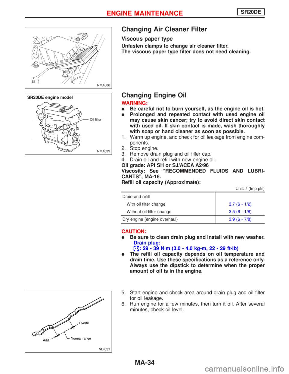
Changing Air Cleaner Filter
Viscous paper type
Unfasten clamps to change air cleaner filter.
The viscous paper type filter does not need cleaning.
Changing Engine Oil
WARNING:
�Be careful not to burn yourself, as the engine oil is hot.
�Prolonged and repeated contact with used engine oil
may cause skin cancer; try to avoid direct skin contact
with used oil. If skin contact is made, wash thoroughly
with soap or hand cleaner as soon as possible.
1. Warm up engine, and check for oil leakage from engine com-
ponents.
2. Stop engine.
3. Remove drain plug and oil filler cap.
4. Drain oil and refill with new engine oil.
Oil grade: API SH or SJ/ACEA A2/96
Viscosity: See“RECOMMENDED FLUIDS AND LUBRI-
CANTS”, MA-16.
Refill oil capacity (Approximate):
Unit:�(Imp pts)
Drain and refill
With oil filter change3.7 (6 - 1/2)
Without oil filter change3.5 (6 - 1/8)
Dry engine (engine overhaul)3.9 (6 - 7/8)
CAUTION:
�Be sure to clean drain plug and install with new washer.
Drain plug:
:29-39N·m (3.0 - 4.0 kg-m, 22 - 29 ft-lb)
�The refill oil capacity depends on oil temperature and
drain time. Use these specifications as a reference only.
Always use the dipstick to determine when the proper
amount of oil is in the engine.
5. Start engine and check area around drain plug and oil filter
for oil leakage.
6. Run engine for a few minutes, then turn it off. After several
minutes, check oil level.
NMA006
NMA039 Oil filter
SR20DE engine model
NDI021 Overfill
Normal range
Add
ENGINE MAINTENANCESR20DE
MA-34
Page 2052 of 2267
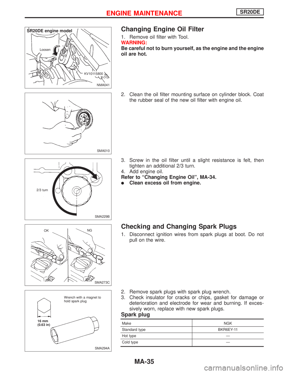
Changing Engine Oil Filter
1. Remove oil filter with Tool.
WARNING:
Be careful not to burn yourself, as the engine and the engine
oil are hot.
2. Clean the oil filter mounting surface on cylinder block. Coat
the rubber seal of the new oil filter with engine oil.
3. Screw in the oil filter until a slight resistance is felt, then
tighten an additional 2/3 turn.
4. Add engine oil.
Refer to“Changing Engine Oil”, MA-34.
�Clean excess oil from engine.
Checking and Changing Spark Plugs
1. Disconnect ignition wires from spark plugs at boot. Do not
pull on the wire.
2. Remove spark plugs with spark plug wrench.
3. Check insulator for cracks or chips, gasket for damage or
deterioration and electrode for wear and burning. If exces-
sively worn, replace with new spark plugs.
Spark plug
Make NGK
Standard type BKR6EY-11
Hot type—
Cold type—
NMA041 Loosen
.KV10115800
.SR20DE engine model
SMA010
SMA229B 2/3 turn
SMA273C OKNG
SMA294A Wrench with a magnet to
hold spark plug
16 mm
(0.63 in)
ENGINE MAINTENANCESR20DE
MA-35
Page 2053 of 2267
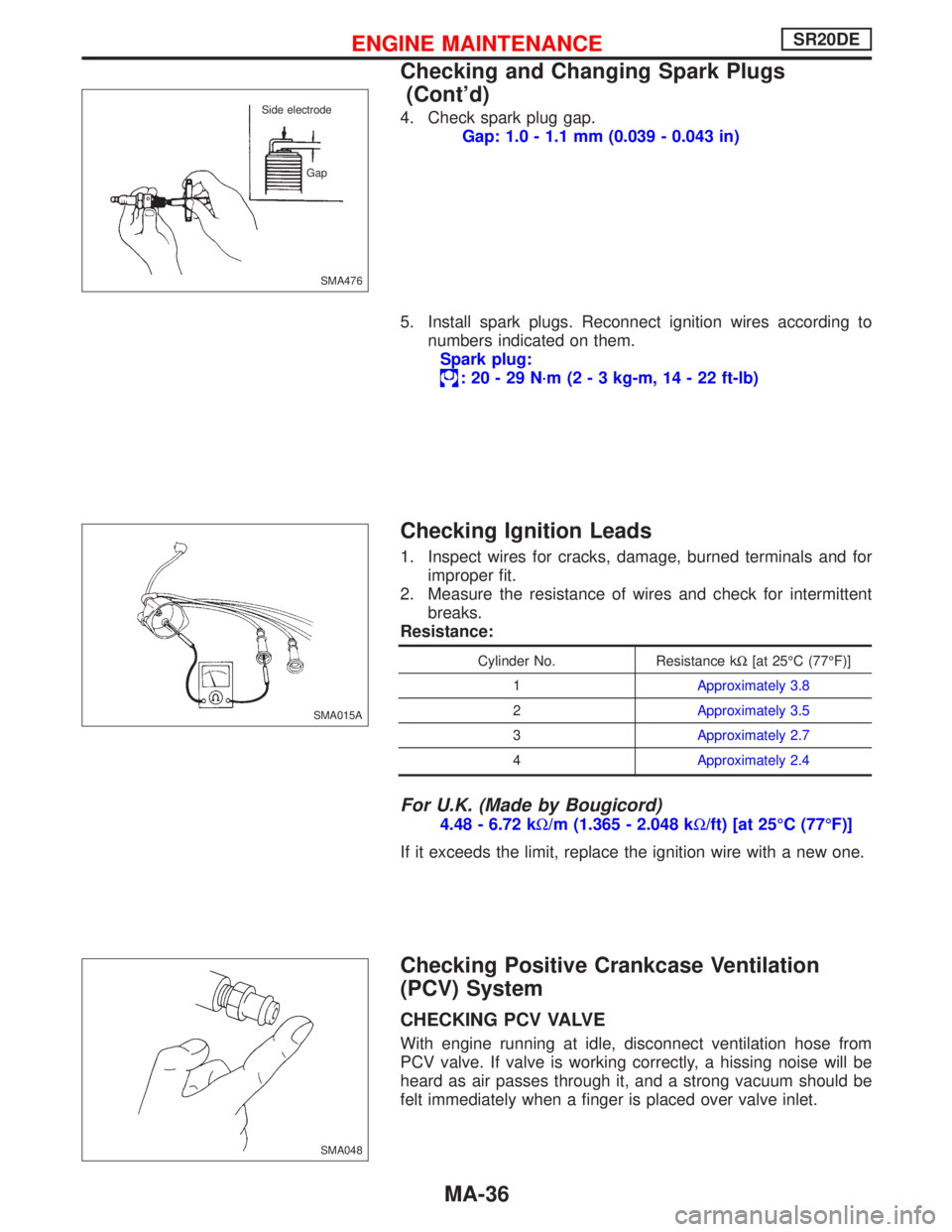
4. Check spark plug gap.
Gap: 1.0 - 1.1 mm (0.039 - 0.043 in)
5. Install spark plugs. Reconnect ignition wires according to
numbers indicated on them.
Spark plug:
:20-29N·m (2 - 3 kg-m, 14 - 22 ft-lb)
Checking Ignition Leads
1. Inspect wires for cracks, damage, burned terminals and for
improper fit.
2. Measure the resistance of wires and check for intermittent
breaks.
Resistance:
Cylinder No. Resistance kΩ[at 25°C (77°F)]
1Approximately 3.8
2Approximately 3.5
3Approximately 2.7
4Approximately 2.4
For U.K. (Made by Bougicord)
4.48 - 6.72 kΩ/m (1.365 - 2.048 kΩ/ft) [at 25°C (77°F)]
If it exceeds the limit, replace the ignition wire with a new one.
Checking Positive Crankcase Ventilation
(PCV) System
CHECKING PCV VALVE
With engine running at idle, disconnect ventilation hose from
PCV valve. If valve is working correctly, a hissing noise will be
heard as air passes through it, and a strong vacuum should be
felt immediately when a finger is placed over valve inlet.
SMA476 Side electrode
Gap
SMA015A
SMA048
ENGINE MAINTENANCESR20DE
Checking and Changing Spark Plugs
(Cont’d)
MA-36
Page 2054 of 2267
CHECKING VENTILATION HOSES
1. Check hoses and hose connections for leaks.
2. Disconnect all hoses and clean with compressed air. If any
hose cannot be freed of obstructions, replace.
Checking Vacuum Hoses and Connections
Check vacuum hoses for leaks, cracks, damage, loose
connections, chafing and deterioration.
Refer to Vacuum Hose Drawing in EMISSION CONTROL
OVERALL SYSTEM in EC section.
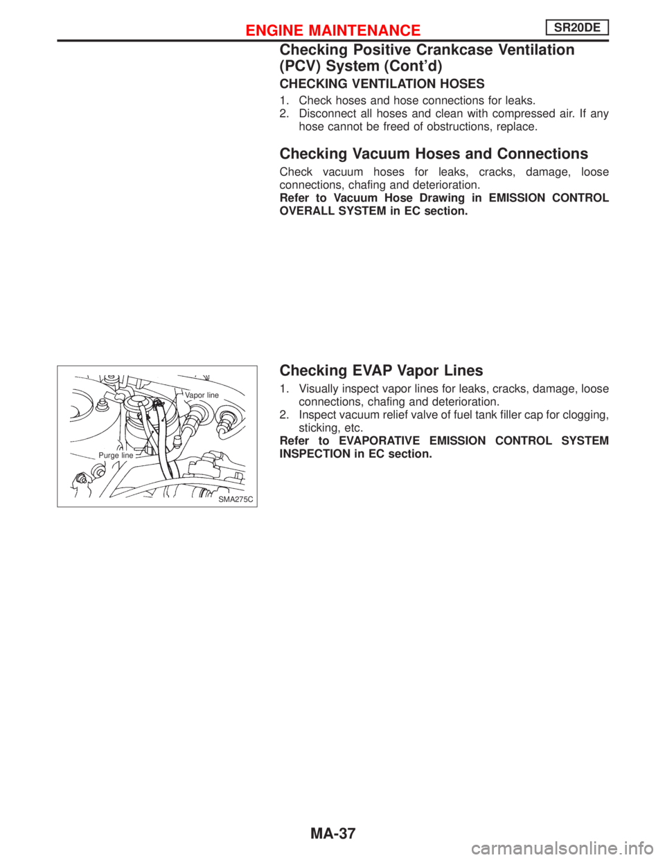
Checking EVAP Vapor Lines
1. Visually inspect vapor lines for leaks, cracks, damage, loose
connections, chafing and deterioration.
2. Inspect vacuum relief valve of fuel tank filler cap for clogging,
sticking, etc.
Refer to EVAPORATIVE EMISSION CONTROL SYSTEM
INSPECTION in EC section.
SMA275C Vapor line
Purge line
ENGINE MAINTENANCESR20DE
Checking Positive Crankcase Ventilation
(PCV) System (Cont’d)
MA-37