Page 1262 of 2267
System Description
INTERIOR LAMP TIMER OPERATION
The time control unit keeps the interior lamp illuminated for about 30 seconds when:
�the ignition key is turned from“ON”to“Acc”to“LOCK”
�the driver’s door is unlocked
�a door is opened and then closed while the ignition switch is in the“OFF”position. (Interior lamp switch
in the“DOOR”position).
The timer is canceled when:
�driver’s door is locked, or
�ignition switch is turned“ON”.
INTERIOR, SPOT, VANITY MIRROR AND LUGGAGE ROOM LAMPS
EL-130
Page 1270 of 2267
System Description
UNIFIED CONTROL METER
�Speedometer, odo/trip meter, tachometer, fuel gauge and water temperature gauge are controlled totally
by control unit combined with speedometer.
�Digital meter is adopted for odo/trip meter.*
*The record of the odometer is kept even if the battery cable is disconnected. The record of the trip meter
is erased when the battery cable is disconnected.
�Odo/trip meter segment can be checked in diagnosis mode.
�Meter/gauge can be checked in diagnosis mode.
METER AND GAUGES
EL-138
Page 1275 of 2267
YEL166C
A/C CONTROL
PANELHEATER ILLUMI-
NATION
.ELECTRIC SPEEDOMETER
TACHOMETER
WATER TEMPERATURE GAUGE
FUEL GAUGE
FUEL WARNING LAMP
TRIP COMPUTER:
TCOUTSIDE AIR TEMPERATURE GAUGE:OG
COMBINATION
METER
: With CVT
: With M/T
: With air conditioner
: Without air conditioner
: With GA engine
: With SR engine or QG engine
: With gasoline engine
: With diesel engine
: With trip computer
: With outside air temperature gauge
THERMAL TRANS-
MITTERFUEL LEVEL
SENSOR UNIT
REFER TO THE FOLLOWING
ELECTRICAL UNITS
ELECTRICAL UNITS
METER AND GAUGES
Wiring Diagram—METER—/MODELS
BEFORE VIN - P11U0548750 (Cont’d)
EL-143
Page 1297 of 2267
Warning Lamps/Schematic
MODELS BEFORE VIN - P11U0548750
YEL167C
GLOW
MALFUNCTION INDICA-
TOR LAMP
ABS
BRAKE
WASH
DOOR
CHARGE
OIL
FUELElectronic
speedometer
module
COMBINATION METER
IGNITION SWITCH
ON or START
FUSE
AIR BAG: M/T models
: CVT models
:H⋅CVT models
:H⋅CVT (M6) models
: With GA engine
: With SR engine or QG engine
: With diesel engine
TIME CON-
TROL UNIT
DIAGNOSIS
SENSOR
UNITFUEL
LEVEL
SENSOR
UNITOIL PRES-
SURE
SWITCHALTER-
NATORFRONT
DOOR
SWITCH
(DRIVER
SIDE)FRONT
DOOR
SWITCH
(PASSEN-
GER SIDE)REAR
DOOR
SWITCH
LHREAR
DOOR
SWITCH
RHWASHER
LEVEL
SWITCHBRAKE
FLUID
LEVEL
SWITCHPARKING
BRAKE
SWITCH
VACUUM
SWITCHSEDIMENTER
SENSOR
ABS
ACTUATOR
AND ELEC-
TRIC UNIT
(CONTROL
UNIT)TCM (TRANS-
MISSION CON-
TROL MODULE)
CVT WARNING LAMP
SPORT INDICATOR LAMP
TRUNK ROOM
LAMP SWITCH
OR
LUGGAGE
ROOM LAMP
SWITCH
ECM
WARNING LAMPS
EL-165
Page 1312 of 2267
System Description
The warning chime is combined with the time control unit.
The light warning chime will not sound, when ignition switch in the ON or START position. (When power
supply exists at time control unit terminal
�1.)
LIGHT WARNING CHIME
With ignition switch in the OFF position, driver’s door open, and lighting switch in 1ST or 2ND position,
warning chime will sound. A battery positive voltage is supplied
�from lighting switch terminal�12or daytime light control unit terminal�6
�to time control unit terminal�10.
Ground is supplied
�through driver side door switch
�to time control unit terminal�6.
WARNING CHIME
EL-180
Page 1315 of 2267
Trouble Diagnoses
SYMPTOM CHART
REFERENCE PAGE EL-183 EL-184 EL-184 EL-185
SYMPTOM
POWER SUPPLY AND
GROUND CIRCUIT CHECK
DIAGNOSTIC PROCEDURE 1
(Lighting switch input signal check)
DIAGNOSTIC PROCEDURE 2
(Key switch input signal check)
DIAGNOSTIC PROCEDURE 3
Light warning chime does not acti-
vate.XX X
Ignition key warning chime does
not activate.XXX
All warning chimes do not activate. X X
POWER SUPPLY AND GROUND CIRCUIT CHECK
Power Supply Circuit Check
Terminals Ignition switch position
��OFF ACC ON
�9GroundBattery
voltageBattery
voltageBattery
voltage
�1Ground 0V 0VBattery
voltage
Ground Circuit Check
Terminals Continuity
�16- Ground Yes
Time control
unit connector
YEL430B
Time control unit connector
YEL431B
WARNING CHIME
EL-183
Page 1316 of 2267

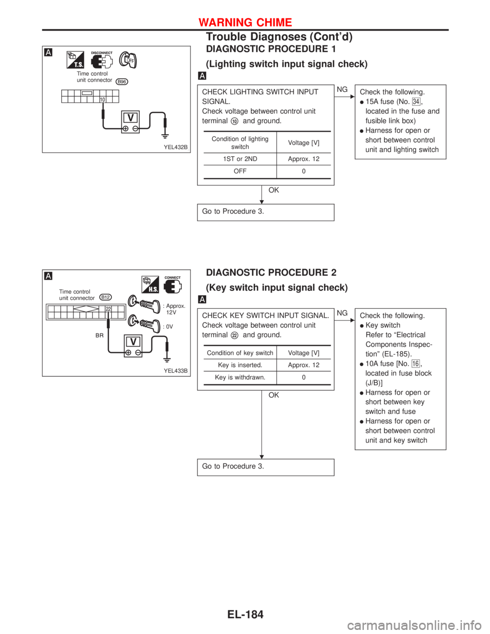
DIAGNOSTIC PROCEDURE 1
(Lighting switch input signal check)
CHECK LIGHTING SWITCH INPUT
SIGNAL.
Check voltage between control unit
terminal
�10and ground.
OK
�NG
Check the following.
�15A fuse (No.34,
located in the fuse and
fusible link box)
�Harness for open or
short between control
unit and lighting switch
Go to Procedure 3.
Condition of lighting
switchVoltage [V]
1ST or 2ND Approx. 12
OFF 0
DIAGNOSTIC PROCEDURE 2
(Key switch input signal check)
CHECK KEY SWITCH INPUT SIGNAL.
Check voltage between control unit
terminal
�22and ground.
OK
�NG
Check the following.
�Key switch
Refer to“Electrical
Components Inspec-
tion”(EL-185).
�10A fuse [No.16,
located in fuse block
(J/B)]
�Harness for open or
short between key
switch and fuse
�Harness for open or
short between control
unit and key switch
Go to Procedure 3.
Condition of key switch Voltage [V]
Key is inserted. Approx. 12
Key is withdrawn. 0
YEL432B
Time control
unit connector
YEL433B
Time control
unit connector
: Approx.
12V
:0V
�
�
WARNING CHIME
Trouble Diagnoses (Cont’d)
EL-184
Page 1317 of 2267

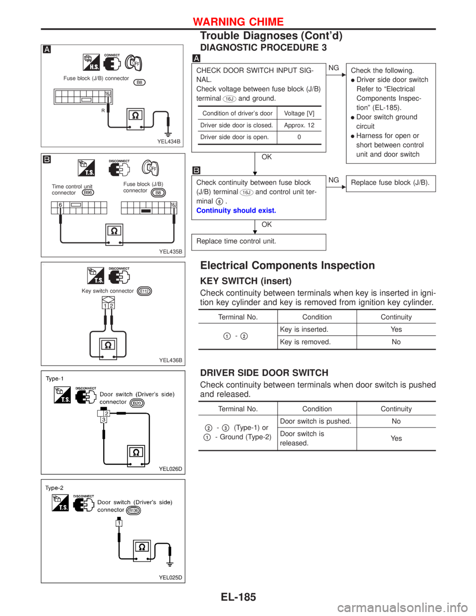
DIAGNOSTIC PROCEDURE 3
CHECK DOOR SWITCH INPUT SIG-
NAL.
Check voltage between fuse block (J/B)
terminal
16Jand ground.
OK
�NG
Check the following.
�Driver side door switch
Refer to“Electrical
Components Inspec-
tion”(EL-185).
�Door switch ground
circuit
�Harness for open or
short between control
unit and door switch
Check continuity between fuse block
(J/B) terminal
16Jand control unit ter-
minal
�6.
Continuity should exist.
OK
�NG
Replace fuse block (J/B).
Replace time control unit.
Condition of driver’s door Voltage [V]
Driver side door is closed. Approx. 12
Driver side door is open. 0
Electrical Components Inspection
KEY SWITCH (insert)
Check continuity between terminals when key is inserted in igni-
tion key cylinder and key is removed from ignition key cylinder.
Terminal No. Condition Continuity
�1-�2Key is inserted. Yes
Key is removed. No
DRIVER SIDE DOOR SWITCH
Check continuity between terminals when door switch is pushed
and released.
Terminal No. Condition Continuity
�2-�3(Type-1) or
�1- Ground (Type-2)Door switch is pushed. No
Door switch is
released.Ye s
YEL434B Fuse block (J/B) connector
YEL435B
Time control unit
connectorFuse block (J/B)
connector
YEL436B Key switch connector
YEL026D
YEL025D
�
�
WARNING CHIME
Trouble Diagnoses (Cont’d)
EL-185