Page 1226 of 2267
YEL837C
HEADLAMP—Headlamp Aiming Control (Auto)—
Wiring Diagram—H/AIM—(Cont’d)
EL-94
Page 1227 of 2267
Trouble Diagnosis
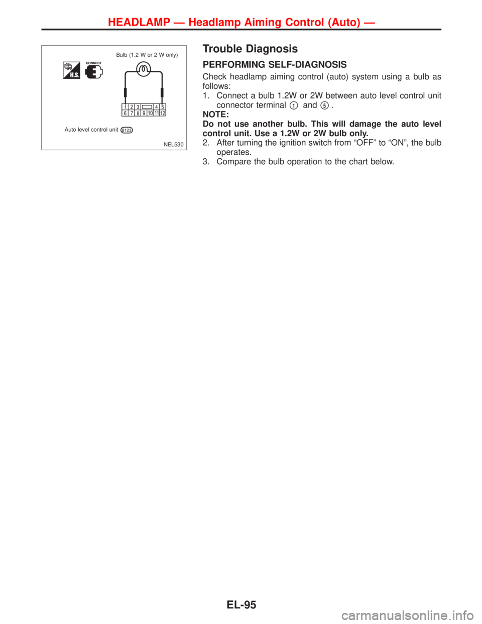
PERFORMING SELF-DIAGNOSIS
Check headlamp aiming control (auto) system using a bulb as
follows:
1. Connect a bulb 1.2W or 2W between auto level control unit
connector terminal
�1and�5.
NOTE:
Do not use another bulb. This will damage the auto level
control unit. Use a 1.2W or 2W bulb only.
2. After turning the ignition switch from“OFF”to“ON”, the bulb
operates.
3. Compare the bulb operation to the chart below.
NEL530
Auto level control unitBulb (1.2 W or 2 W only)
HEADLAMP—Headlamp Aiming Control (Auto)—
EL-95
Page 1228 of 2267
Lighting condition of the bulb System condition Reference item
NEL531 IGN ON
ON
OFF1 sec.
No malfunction is detected.
No further action is neces-
sary.
—
NEL532 IGN ON
ON
OFF1 sec.2 sec. 2 sec.
0.5 sec.
Front sensor or front sensor
circuit is malfunctioning.
(When rear sensor OK)Go to DIAGNOSTIC
PROCEDURE 1
(EL-97).
NEL533 IGN ON
ON
OFF1 sec.2 sec. 2 sec.
0.5 sec. 0.5 sec.
Rear sensor or rear sensor
circuit is malfunctioning.
(Whatever the state of front
sensor)Go to DIAGNOSTIC
PROCEDURE 2
(EL-97).
NEL534 IGN ON
ON
OFF1 sec.2 sec. 2 sec.
0.5 sec. 0.5 sec.
Sensor supply is malfunction-
ing.Go to DIAGNOSTIC
PROCEDURE 1 and
2 (EL-97).
NEL535 IGN ON
ON
OFF1 sec.2 sec. 2 sec.
0.5 sec. 0.5 sec.
Aiming motor or aiming motor
circuit is malfunctioning.Go to DIAGNOSTIC
PROCEDURE 3
(EL-98).
NEL536 IGN ON
ON
OFF
Auto level control unit is mal-
functioning.Replace auto level
control unit.
HEADLAMP—Headlamp Aiming Control (Auto)—
Trouble Diagnosis (Cont’d)
EL-96
Page 1229 of 2267
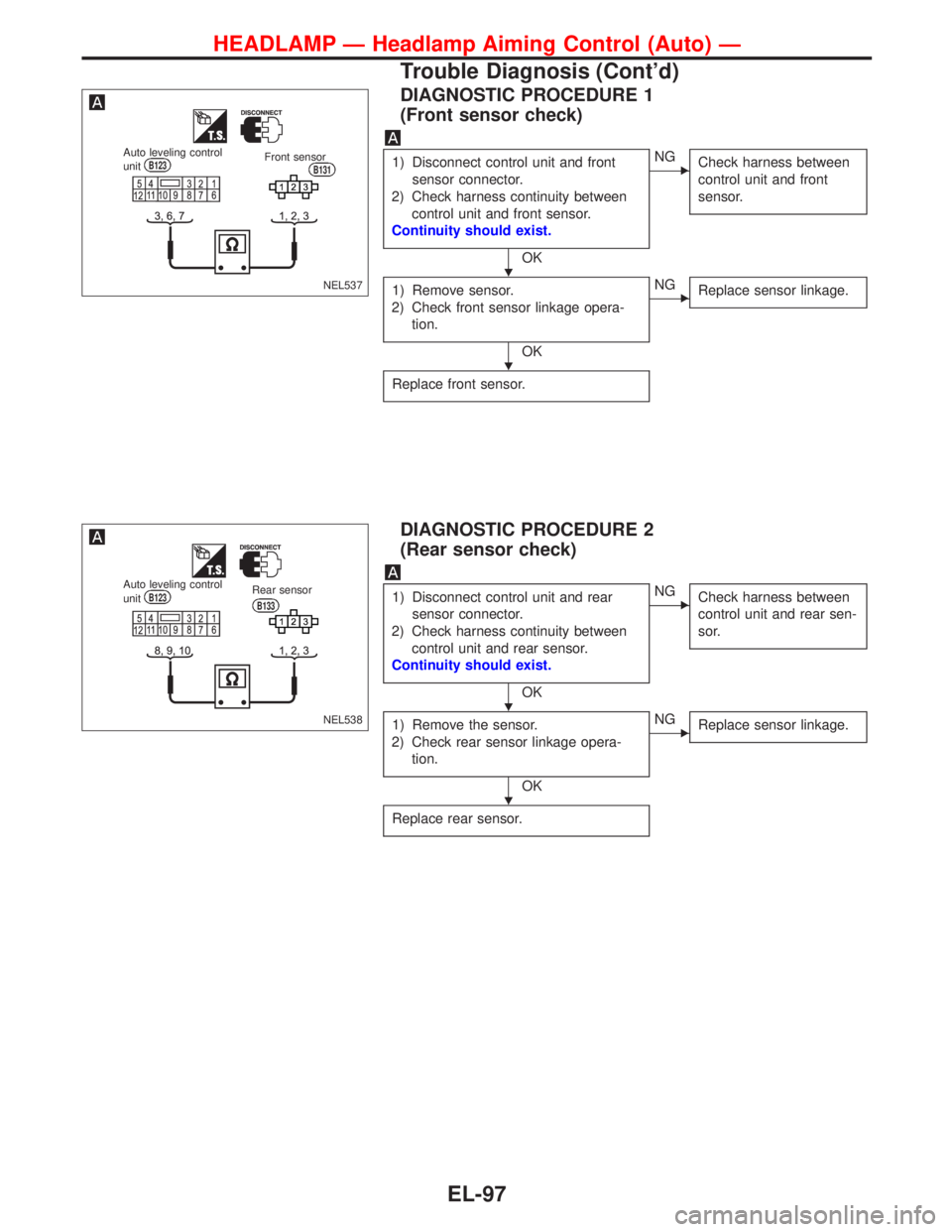
DIAGNOSTIC PROCEDURE 1
(Front sensor check)
1) Disconnect control unit and front
sensor connector.
2) Check harness continuity between
control unit and front sensor.
Continuity should exist.
OK
�NG
Check harness between
control unit and front
sensor.
1) Remove sensor.
2) Check front sensor linkage opera-
tion.
OK
�NG
Replace sensor linkage.
Replace front sensor.
DIAGNOSTIC PROCEDURE 2
(Rear sensor check)
1) Disconnect control unit and rear
sensor connector.
2) Check harness continuity between
control unit and rear sensor.
Continuity should exist.
OK
�NG
Check harness between
control unit and rear sen-
sor.
1) Remove the sensor.
2) Check rear sensor linkage opera-
tion.
OK
�NG
Replace sensor linkage.
Replace rear sensor.
NEL537
Auto leveling control
unitB123Front sensorB131
NEL538
Auto leveling control
unitB123Rear sensor
B133
�
�
�
�
HEADLAMP—Headlamp Aiming Control (Auto)—
Trouble Diagnosis (Cont’d)
EL-97
Page 1230 of 2267
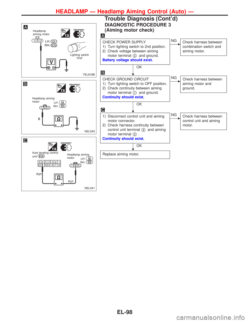
DIAGNOSTIC PROCEDURE 3
(Aiming motor check)
CHECK POWER SUPPLY
1) Turn lighting switch to 2nd position.
2) Check voltage between aiming
motor terminal
�3and ground.
Battery voltage should exist.
OK
�NG
Check harness between
combination switch and
aiming motor.
CHECK GROUND CIRCUIT
1) Turn lighting switch to OFF position.
2) Check continuity between aiming
motor terminal
�1and ground.
Continuity should exist.
OK
�NG
Check harness between
aiming motor and
ground.
1) Disconnect control unit and aiming
motor connector.
2) Check harness continuity between
control unit terminal
�4and aiming
motor terminal
�2.
Continuity should exist.
OK
�NG
Check harness between
control unit and aiming
motor.
Replace aiming motor.
YEL618B
Headlamp
aiming motor
Lighting switch
“2nd”
NEL540
Headlamp aiming
motor
LH:E4RH:E33
NEL541
Auto leveling control
unitB123Headlamp aiming
motor
LH:E4RH:E33
�
�
�
HEADLAMP—Headlamp Aiming Control (Auto)—
Trouble Diagnosis (Cont’d)
EL-98
Page 1231 of 2267
Removal and Installation
Front sensor
YEL621B
4.0 - 5.0 (0.4 - 0.51, 35 - 44)
Front linkage to be clamped onto
stabilizer bar with wheels down
and suspension settled. Rotation
to be fixed with link arm in hori-
zontal plane.
18 mm (0.71 in)
3.3 - 7.7 (0.33 - 0.79, 29 - 68)
Rear sensor
3.3 - 7.7 (0.33 - 0.79, 29 - 68)
:N·m (kg-m, in-lb)3.3 - 7.7 (0.33 - 0.79, 29 - 68)The rear sensor linkage does not
require setting, but with the wheel on
the ground and the suspension
settled, ensure that the link arm in the
same plane as the connector wire.
HEADLAMP—Headlamp Aiming Control (Auto)—
EL-99
Page 1255 of 2267

Trouble Diagnoses
Symptom Possible cause Repair order
Turn signal and hazard warning
lamps do not operate.1. Hazard switch 1. Check hazard switch.
2. Turn signal switch 2. Check turn signal switch.
3. Harness connector
E1043. Check harness connectorE104.
Turn signal lamps do not operate
but hazard warning lamps oper-
ate.1. Turn signal switch 1. Check turn signal switch.
2. Open in turn signal switch cir-
cuit2. Check L/G and G/Y wires between time control
unit and turn signal switch for open circuit.
3. Check B wire between turn signal switch and
ground for open circuit.
Hazard warning lamps do not
operate but turn signal lamps
operate.1. Hazard switch 1. Check hazard switch.
2. Open in hazard switch circuit 2. Check G/R wire between time control unit and
hazard switch for open circuit.
Check B wire between hazard switch unit and
ground for open circuit.
Front turn signal lamp LH or RH
does not operate.1. Bulb 1. Check bulb.
2. Grounds 2. Check grounds
E11andE37.
Rear turn signal lamp LH or RH
does not operate.1. Bulb 1. Check bulb.
2. Grounds 2. Check grounds
T3andT4orB48andD110
orB150andB151.
LH and RH turn indicators do not
operate.1. Grounds 1. Check grounds
E11andE37.
LH or RH turn indicator does not
operate.1. Bulb 1. Check bulb in combination meter.
TURN SIGNAL AND HAZARD WARNING LAMPS
EL-123
Page 1257 of 2267
Wiring Diagram—ILL—
MODELS BEFORE VIN - P11U0548750
YEL157C
BATTERY
Refer to EL-POWER. IGNITION SWITCH
ON or START
FUSE
BLOCK
(J/B)
OFF1ST2ND
COMBINATION
SWITCH
(LIGHTING SWITCH)
COMBINATION
METER
(ILLUMINATION)
DAYTIME LIGHT
CONTROL
UNIT
: With daytime light system
: Without daytime light system
REFER TO THE FOLLOWING
FUSE BLOCK - Junction Box (J/B)
FUSE BLOCK - Junction Box (J/B) Next
page
HEAD LAMP
WASHER
SWITCH
(ILLUMINATION)
ILLUMINATION
EL-125
—
Wiring Diagram—H/AIM—(Cont’d)
EL-94")


Front linkage to be clamped onto
stabilizer bar with wheels down
and suspension settled. Rotation
to be fixed with link ar")

OFF1ST2ND
COMBINATION
SWITCH
(LIGHTING SWITCH)
COMBINATION
METER")