Page 1081 of 2267
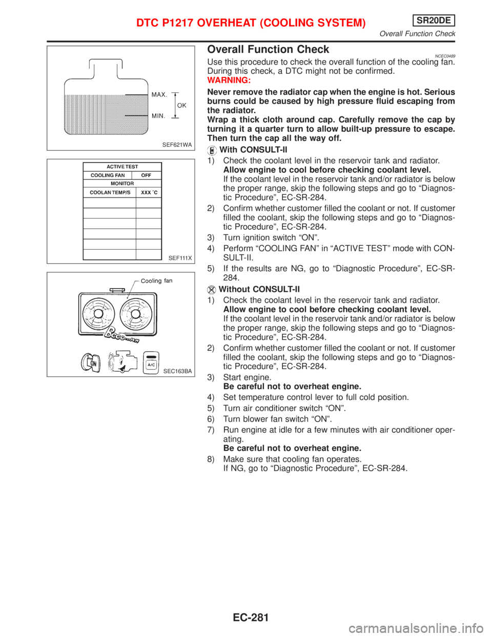
Overall Function CheckNCEC0489Use this procedure to check the overall function of the cooling fan.
During this check, a DTC might not be confirmed.
WARNING:
Never remove the radiator cap when the engine is hot. Serious
burns could be caused by high pressure fluid escaping from
the radiator.
Wrap a thick cloth around cap. Carefully remove the cap by
turning it a quarter turn to allow built-up pressure to escape.
Then turn the cap all the way off.
With CONSULT-II
1) Check the coolant level in the reservoir tank and radiator.
Allow engine to cool before checking coolant level.
If the coolant level in the reservoir tank and/or radiator is below
the proper range, skip the following steps and go to ªDiagnos-
tic Procedureº, EC-SR-284.
2) Confirm whether customer filled the coolant or not. If customer
filled the coolant, skip the following steps and go to ªDiagnos-
tic Procedureº, EC-SR-284.
3) Turn ignition switch ªONº.
4) Perform ªCOOLING FANº in ªACTIVE TESTº mode with CON-
SULT-II.
5) If the results are NG, go to ªDiagnostic Procedureº, EC-SR-
284.
Without CONSULT-II
1) Check the coolant level in the reservoir tank and radiator.
Allow engine to cool before checking coolant level.
If the coolant level in the reservoir tank and/or radiator is below
the proper range, skip the following steps and go to ªDiagnos-
tic Procedureº, EC-SR-284.
2) Confirm whether customer filled the coolant or not. If customer
filled the coolant, skip the following steps and go to ªDiagnos-
tic Procedureº, EC-SR-284.
3) Start engine.
Be careful not to overheat engine.
4) Set temperature control lever to full cold position.
5) Turn air conditioner switch ªONº.
6) Turn blower fan switch ªONº.
7) Run engine at idle for a few minutes with air conditioner oper-
ating.
Be careful not to overheat engine.
8) Make sure that cooling fan operates.
If NG, go to ªDiagnostic Procedureº, EC-SR-284.
SEF621WA
SEF111X
SEC163BA
DTC P1217 OVERHEAT (COOLING SYSTEM)SR20DE
Overall Function Check
EC-281
Page 1083 of 2267
YEC848
: Detectable line for DTC
: Non-detectable line for DTC
: Hyper CVT models REFRIGERANT
SENSOR
TCM
(TRANSMISSION
CONTROL
MODULE) ECM
DTC P1217 OVERHEAT (COOLING SYSTEM)SR20DE
Wiring Diagram (Cont'd)
EC-283
Page 1090 of 2267
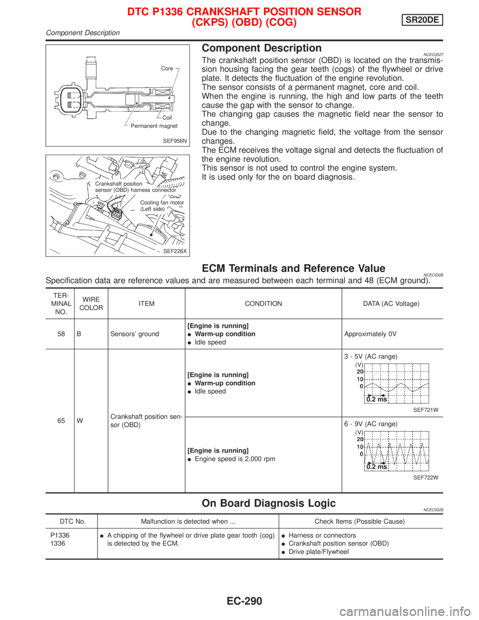
Component DescriptionNCEC0327The crankshaft position sensor (OBD) is located on the transmis-
sion housing facing the gear teeth (cogs) of the flywheel or drive
plate. It detects the fluctuation of the engine revolution.
The sensor consists of a permanent magnet, core and coil.
When the engine is running, the high and low parts of the teeth
cause the gap with the sensor to change.
The changing gap causes the magnetic field near the sensor to
change.
Due to the changing magnetic field, the voltage from the sensor
changes.
The ECM receives the voltage signal and detects the fluctuation of
the engine revolution.
This sensor is not used to control the engine system.
It is used only for the on board diagnosis.
ECM Terminals and Reference ValueNCEC0328Specification data are reference values and are measured between each terminal and 48 (ECM ground).
TER-
MINAL
NO.WIRE
COLORITEM CONDITION DATA (AC Voltage)
58 B Sensors' ground[Engine is running]
IWarm-up condition
IIdle speedApproximately 0V
65 WCrankshaft position sen-
sor (OBD)[Engine is running]
IWarm-up condition
IIdle speed3 - 5V (AC range)
SEF721W
0.2 ms
[Engine is running]
IEngine speed is 2,000 rpm6 - 9V (AC range)
SEF722W
0.2 ms
On Board Diagnosis LogicNCEC0329
DTC No. Malfunction is detected when ... Check Items (Possible Cause)
P1336
1336IA chipping of the flywheel or drive plate gear tooth (cog)
is detected by the ECM.IHarness or connectors
ICrankshaft position sensor (OBD)
IDrive plate/Flywheel
SEF956N Core
Permanent magnetCoil
SEF226X Crankshaft position
sensor (OBD) harness connector
Cooling fan motor
(Left side)
DTC P1336 CRANKSHAFT POSITION SENSOR
(CKPS) (OBD) (COG)SR20DE
Component Description
EC-290
Page 1092 of 2267
Wiring DiagramNCEC0331
YEC839
: Detectable line for DTC
: Non-detectable line for DTC
: Hyper CVT models
ECMTCM
(TRANSMISSION
CONTROL
MODULE) CRANKSHAFT
POSITION
SENSOR (OBD)
DTC P1336 CRANKSHAFT POSITION SENSOR
(CKPS) (OBD) (COG)SR20DE
Wiring Diagram
EC-292
Page 1093 of 2267
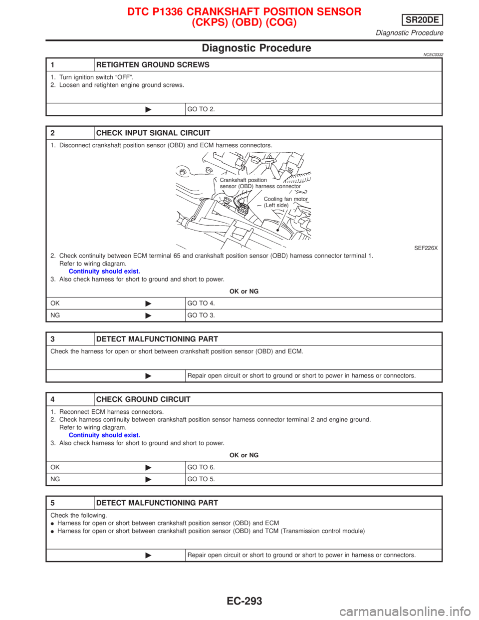
Diagnostic ProcedureNCEC0332
1 RETIGHTEN GROUND SCREWS
1. Turn ignition switch ªOFFº.
2. Loosen and retighten engine ground screws.
©GO TO 2.
2 CHECK INPUT SIGNAL CIRCUIT
1. Disconnect crankshaft position sensor (OBD) and ECM harness connectors.
SEF226X2. Check continuity between ECM terminal 65 and crankshaft position sensor (OBD) harness connector terminal 1.
Refer to wiring diagram.
Continuity should exist.
3. Also check harness for short to ground and short to power.
OK or NG
OK©GO TO 4.
NG©GO TO 3.
3 DETECT MALFUNCTIONING PART
Check the harness for open or short between crankshaft position sensor (OBD) and ECM.
©Repair open circuit or short to ground or short to power in harness or connectors.
4 CHECK GROUND CIRCUIT
1. Reconnect ECM harness connectors.
2. Check harness continuity between crankshaft position sensor harness connector terminal 2 and engine ground.
Refer to wiring diagram.
Continuity should exist.
3. Also check harness for short to ground and short to power.
OK or NG
OK©GO TO 6.
NG©GO TO 5.
5 DETECT MALFUNCTIONING PART
Check the following.
IHarness for open or short between crankshaft position sensor (OBD) and ECM
IHarness for open or short between crankshaft position sensor (OBD) and TCM (Transmission control module)
©Repair open circuit or short to ground or short to power in harness or connectors.
Crankshaft position
sensor (OBD) harness connector
Cooling fan motor
(Left side)
DTC P1336 CRANKSHAFT POSITION SENSOR
(CKPS) (OBD) (COG)SR20DE
Diagnostic Procedure
EC-293
Page 1095 of 2267
System DescriptionNCEC0560The malfunction information related to CVT is transferred through the line (circuit) from TCM (Transmission
Control Module) to ECM. Therefore, be sure to erase the malfunction information such as DTC not only in TCM
(Transmission Control Module) but also ECM after the CVT related repair.
ECM Terminals and Reference ValueNCEC0561Specification data are reference values and are measured between each terminal and 48 (ECM ground).
TER-
MINAL
NO.WIRE
COLORITEM CONDITION DATA (DC Voltage)
91 PU/Y CVT check signal[Ignition switch ªONº]
[Engine is running]0 - Approximately 5V
On Board Diagnosis LogicNCEC0562
DTC No. Malfunction is detected when ... Check Items (Possible Cause)
P1605
1605IAn incorrect signal from TCM (Transmission Control
Module) is sent to ECM.IHarness or connectors
[The communication line circuit between ECM and
TCM (Transmission Control Module) is open or
shorted.]
IDead (Weak) battery
ITCM (Transmission Control Module)
DTC Confirmation ProcedureNCEC0563NOTE:
If ªDTC CONFIRMATION PROCEDUREº has been previously
conducted, always turn ignition switch ªOFFº and wait at least 9
seconds before conducting the next test.
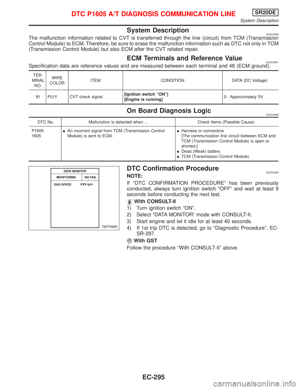
With CONSULT-II
1) Turn ignition switch ªONº.
2) Select ªDATA MONITORº mode with CONSULT-II.
3) Start engine and let it idle for at least 40 seconds.
4) If 1st trip DTC is detected, go to ªDiagnostic Procedureº, EC-
SR-297.
With GST
Follow the procedure ªWith CONSULT-IIº above.
NEF068A
DTC P1605 A/T DIAGNOSIS COMMUNICATION LINESR20DE
System Description
EC-295
Page 1096 of 2267
Wiring DiagramNCEC0564
YEC850
: Detectable line for DTC
: Non-detectable line for DTC TCM
(TRANSMISSION
CONTROL
MODULE)
ECM
F101
.ATCK
DTC P1605 A/T DIAGNOSIS COMMUNICATION LINESR20DE
Wiring Diagram
EC-296
Page 1102 of 2267
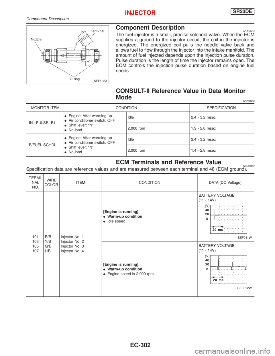
Component DescriptionNCEC0435The fuel injector is a small, precise solenoid valve. When the ECM
supplies a ground to the injector circuit, the coil in the injector is
energized. The energized coil pulls the needle valve back and
allows fuel to flow through the injector into the intake manifold. The
amount of fuel injected depends upon the injection pulse duration.
Pulse duration is the length of time the injector remains open. The
ECM controls the injection pulse duration based on engine fuel
needs.
CONSULT-II Reference Value in Data Monitor
Mode
NCEC0436
MONITOR ITEM CONDITION SPECIFICATION
INJ PULSE -B1IEngine: After warming up
IAir conditioner switch: OFF
IShift lever: ªNº
INo-loadIdle 2.4 - 3.2 msec
2,000 rpm 1.9 - 2.8 msec
B/FUEL SCHDLIEngine: After warming up
IAir conditioner switch: OFF
IShift lever: ªNº
INo-loadIdle 2.4 - 3.2 msec
2,000 rpm 1.4 - 2.8 msec
ECM Terminals and Reference ValueNCEC0437Specification data are reference values and are measured between each terminal and 48 (ECM ground).
TERMI-
NAL
NO.WIRE
COLORITEM CONDITION DATA (DC Voltage)
101
103
105
107R/B
Y/B
G/B
L/BInjector No. 1
Injector No. 2
Injector No. 3
Injector No. 4[Engine is running]
IWarm-up condition
IIdle speedBATTERY VOLTAGE
(11 - 14V)
SEF011W
[Engine is running]
IWarm-up condition
IEngine speed is 2,000 rpmBATTERY VOLTAGE
(11 - 14V)
SEF012W
SEF138X
INJECTORSR20DE
Component Description
EC-302