1999 NISSAN PRIMERA Control
[x] Cancel search: ControlPage 1012 of 2267
On Board Diagnosis LogicNCEC0188With the Air/Fuel Mixture Ratio Self-Learning Control, the actual mixture ratio can be brought closely to the
theoretical mixture ratio based on the mixture ratio feedback signal from the heated oxygen sensor 1 (front).
The ECM calculates the necessary compensation to correct the offset between the actual and the theoretical
ratios.
In case the amount of the compensation value is extremely large (The actual mixture ratio is too lean.), the
ECM judges the condition as the fuel injection system malfunction and lights up the MI (2 trip detection logic).
Sensor Input Signal to ECMECM func-
tionActuator
Heated oxygen sensor 1 (front)Density of oxygen in exhaust gas
(Mixture ratio feedback signal)Fuel injec-
tion & mix-
ture ratio
controlInjectors
DTC No. Malfunction is detected when ... Check Items (Possible Cause)
P0171
0171IFuel injection system does not operate properly.
IThe amount of mixture ratio compensation is too large.
(The mixture ratio is too lean.)IIntake air leaks
IHeated oxygen sensor 1 (front)
IInjectors
IExhaust gas leaks
IIncorrect fuel pressure
ILack of fuel
IMass air flow sensor
DTC Confirmation ProcedureNCEC0189NOTE:
If ªDTC Confirmation Procedureº has been previously conducted,
always turn ignition switch ªOFFº and wait at least 9 seconds
before conducting the next test.
TESTING CONDITION:
IAlways perform at a temperature above þ10ÉC (14ÉF).
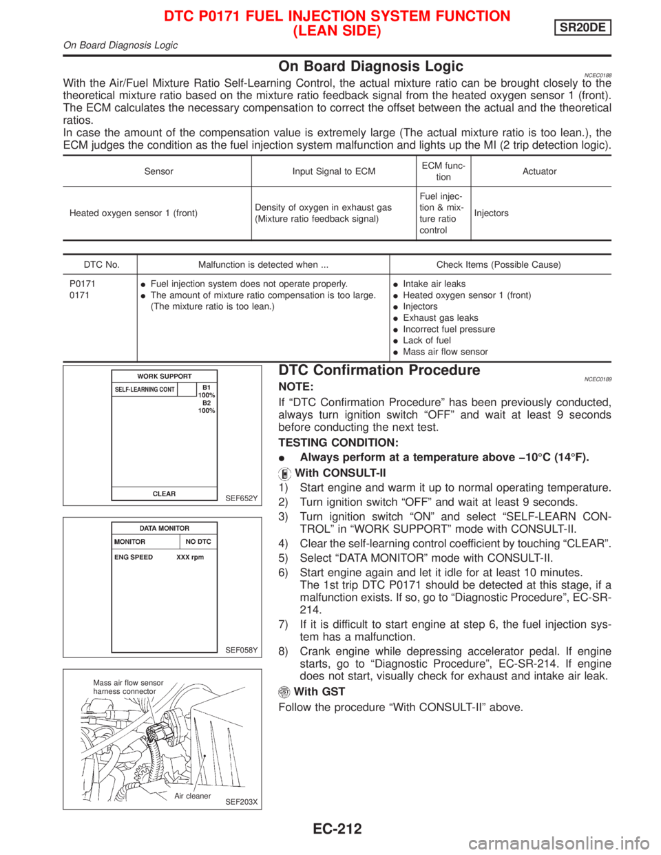
With CONSULT-II
1) Start engine and warm it up to normal operating temperature.
2) Turn ignition switch ªOFFº and wait at least 9 seconds.
3) Turn ignition switch ªONº and select ªSELF-LEARN CON-
TROLº in ªWORK SUPPORTº mode with CONSULT-II.
4) Clear the self-learning control coefficient by touching ªCLEARº.
5) Select ªDATA MONITORº mode with CONSULT-II.
6) Start engine again and let it idle for at least 10 minutes.
The 1st trip DTC P0171 should be detected at this stage, if a
malfunction exists. If so, go to ªDiagnostic Procedureº, EC-SR-
214.
7) If it is difficult to start engine at step 6, the fuel injection sys-
tem has a malfunction.
8) Crank engine while depressing accelerator pedal. If engine
starts, go to ªDiagnostic Procedureº, EC-SR-214. If engine
does not start, visually check for exhaust and intake air leak.
With GST
Follow the procedure ªWith CONSULT-IIº above.
SEF652Y
SEF058Y
SEF203X Mass air flow sensor
harness connector
Air cleaner
DTC P0171 FUEL INJECTION SYSTEM FUNCTION
(LEAN SIDE)SR20DE
On Board Diagnosis Logic
EC-212
Page 1018 of 2267
On Board Diagnosis LogicNCEC0192With the Air/Fuel Mixture Ratio Self-Learning Control, the actual mixture ratio can be brought closely to the
theoretical mixture ratio based on the mixture ratio feedback signal from the heated oxygen sensor 1 (front).
The ECM calculates the necessary compensation to correct the offset between the actual and the theoretical
ratios.
In case the amount of the compensation value is extremely large (The actual mixture ratio is too rich.), the
ECM judges the condition as a fuel injection system malfunction and lights up the MI (2 trip detection logic).
Sensor Input Signal to ECMECM func-
tionActuator
Heated oxygen sensor 1 (front)Density of oxygen in exhaust gas
(Mixture ratio feedback signal)Fuel injec-
tion & mix-
ture ratio
controlInjectors
DTC No. Malfunction is detected when ... Check Items (Possible Cause)
P0172
0172IFuel injection system does not operate properly.
IThe amount of mixture ratio compensation is too large.
(The mixture ratio is too rich.)IHeated oxygen sensor 1 (front)
IInjectors
IExhaust gas leaks
IIncorrect fuel pressure
IMass air flow sensor
DTC Confirmation ProcedureNCEC0193NOTE:
If ªDTC Confirmation Procedure º has been previously conducted,
always turn ignition switch ªOFFº and wait at least 9 seconds
before conducting the next test.
TESTING CONDITION:
IAlways perform at a temperature above þ10ÉC (14ÉF).
With CONSULT-II
1) Start engine and warm it up to normal operating temperature.
2) Turn ignition switch ªOFFº and wait at least 9 seconds.
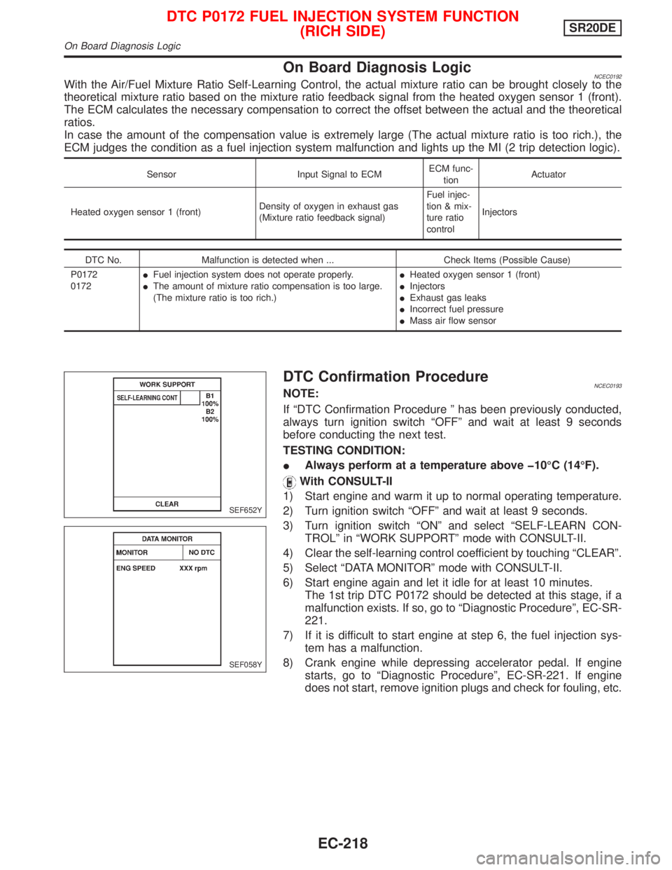
3) Turn ignition switch ªONº and select ªSELF-LEARN CON-
TROLº in ªWORK SUPPORTº mode with CONSULT-II.
4) Clear the self-learning control coefficient by touching ªCLEARº.
5) Select ªDATA MONITORº mode with CONSULT-II.
6) Start engine again and let it idle for at least 10 minutes.
The 1st trip DTC P0172 should be detected at this stage, if a
malfunction exists. If so, go to ªDiagnostic Procedureº, EC-SR-
221.
7) If it is difficult to start engine at step 6, the fuel injection sys-
tem has a malfunction.
8) Crank engine while depressing accelerator pedal. If engine
starts, go to ªDiagnostic Procedureº, EC-SR-221. If engine
does not start, remove ignition plugs and check for fouling, etc.
SEF652Y
SEF058Y
DTC P0172 FUEL INJECTION SYSTEM FUNCTION
(RICH SIDE)SR20DE
On Board Diagnosis Logic
EC-218
Page 1034 of 2267
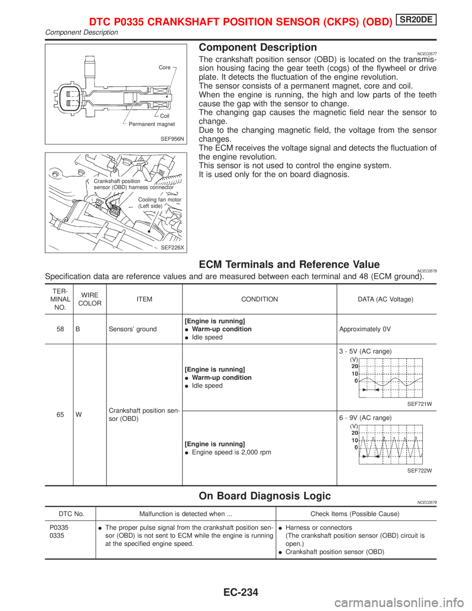
Component DescriptionNCEC0577The crankshaft position sensor (OBD) is located on the transmis-
sion housing facing the gear teeth (cogs) of the flywheel or drive
plate. It detects the fluctuation of the engine revolution.
The sensor consists of a permanent magnet, core and coil.
When the engine is running, the high and low parts of the teeth
cause the gap with the sensor to change.
The changing gap causes the magnetic field near the sensor to
change.
Due to the changing magnetic field, the voltage from the sensor
changes.
The ECM receives the voltage signal and detects the fluctuation of
the engine revolution.
This sensor is not used to control the engine system.
It is used only for the on board diagnosis.
ECM Terminals and Reference ValueNCEC0578Specification data are reference values and are measured between each terminal and 48 (ECM ground).
TER-
MINAL
NO.WIRE
COLORITEM CONDITION DATA (AC Voltage)
58 B Sensors' ground[Engine is running]
IWarm-up condition
IIdle speedApproximately 0V
65 WCrankshaft position sen-
sor (OBD)[Engine is running]
IWarm-up condition
IIdle speed3 - 5V (AC range)
SEF721W
[Engine is running]
IEngine speed is 2,000 rpm6 - 9V (AC range)
SEF722W
On Board Diagnosis LogicNCEC0579
DTC No. Malfunction is detected when ... Check Items (Possible Cause)
P0335
0335IThe proper pulse signal from the crankshaft position sen-
sor (OBD) is not sent to ECM while the engine is running
at the specified engine speed.IHarness or connectors
(The crankshaft position sensor (OBD) circuit is
open.)
ICrankshaft position sensor (OBD)
SEF956N Core
Permanent magnetCoil
SEF226X Crankshaft position
sensor (OBD) harness connector
Cooling fan motor
(Left side)
DTC P0335 CRANKSHAFT POSITION SENSOR (CKPS) (OBD)SR20DE
Component Description
EC-234
Page 1036 of 2267
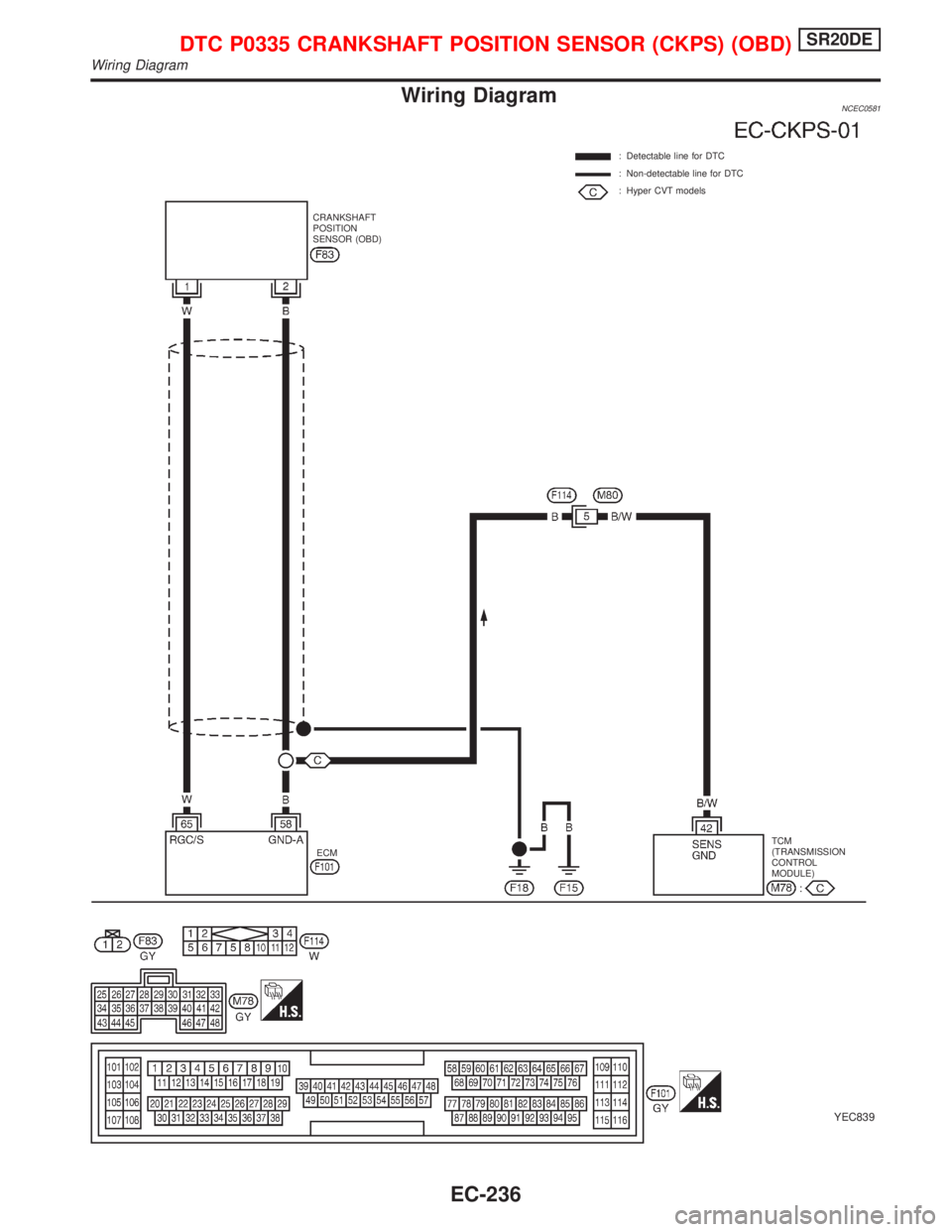
Wiring DiagramNCEC0581
YEC839
: Detectable line for DTC
: Non-detectable line for DTC
: Hyper CVT models
ECMTCM
(TRANSMISSION
CONTROL
MODULE) CRANKSHAFT
POSITION
SENSOR (OBD)
DTC P0335 CRANKSHAFT POSITION SENSOR (CKPS) (OBD)SR20DE
Wiring Diagram
EC-236
Page 1037 of 2267
Diagnostic ProcedureNCEC0582
1 RETIGHTEN GROUND SCREWS
1. Turn ignition switch ªOFFº.
2. Loosen and retighten engine ground screws.
©GO TO 2.
2 CHECK INPUT SIGNAL CIRCUIT
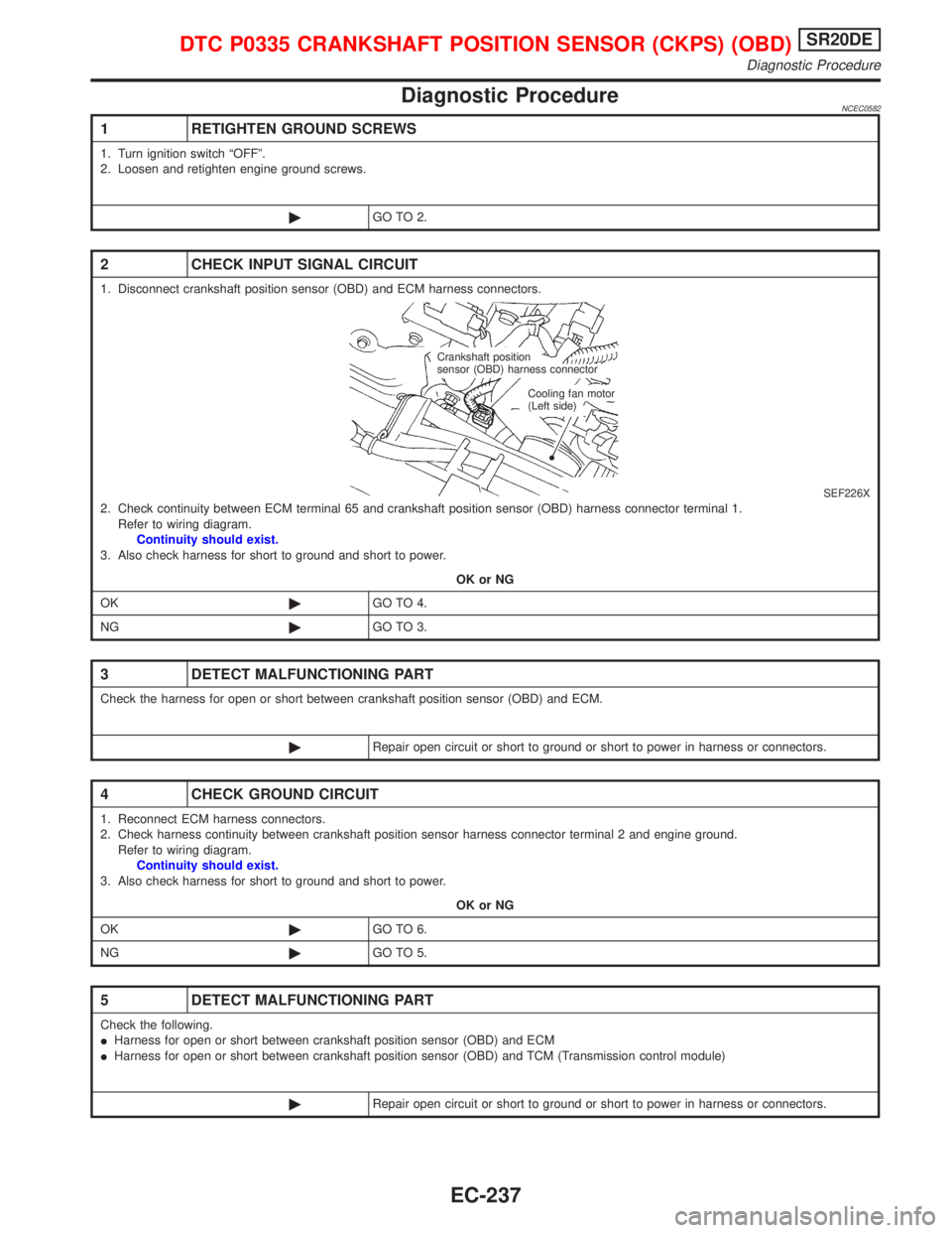
1. Disconnect crankshaft position sensor (OBD) and ECM harness connectors.
SEF226X2. Check continuity between ECM terminal 65 and crankshaft position sensor (OBD) harness connector terminal 1.
Refer to wiring diagram.
Continuity should exist.
3. Also check harness for short to ground and short to power.
OK or NG
OK©GO TO 4.
NG©GO TO 3.
3 DETECT MALFUNCTIONING PART
Check the harness for open or short between crankshaft position sensor (OBD) and ECM.
©Repair open circuit or short to ground or short to power in harness or connectors.
4 CHECK GROUND CIRCUIT
1. Reconnect ECM harness connectors.
2. Check harness continuity between crankshaft position sensor harness connector terminal 2 and engine ground.
Refer to wiring diagram.
Continuity should exist.
3. Also check harness for short to ground and short to power.
OK or NG
OK©GO TO 6.
NG©GO TO 5.
5 DETECT MALFUNCTIONING PART
Check the following.
IHarness for open or short between crankshaft position sensor (OBD) and ECM
IHarness for open or short between crankshaft position sensor (OBD) and TCM (Transmission control module)
©Repair open circuit or short to ground or short to power in harness or connectors.
Crankshaft position
sensor (OBD) harness connector
Cooling fan motor
(Left side)
DTC P0335 CRANKSHAFT POSITION SENSOR (CKPS) (OBD)SR20DE
Diagnostic Procedure
EC-237
Page 1039 of 2267
Component DescriptionNCEC0220The camshaft position sensor is a basic component of the engine
control system. It monitors engine speed and piston position.
These input signals to the engine control system are used to con-
trol fuel injection, ignition timing and other functions.
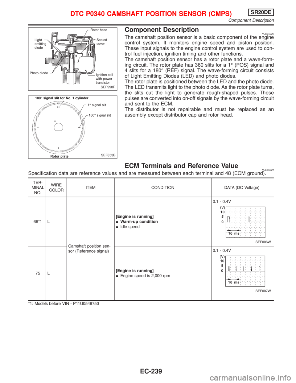
The camshaft position sensor has a rotor plate and a wave-form-
ing circuit. The rotor plate has 360 slits for a 1É (POS) signal and
4 slits for a 180É (REF) signal. The wave-forming circuit consists
of Light Emitting Diodes (LED) and photo diodes.
The rotor plate is positioned between the LED and the photo diode.
The LED transmits light to the photo diode. As the rotor plate turns,
the slits cut the light to generate rough-shaped pulses. These
pulses are converted into on-off signals by the wave-forming circuit
and sent to the ECM.
The distributor is not repairable and must be replaced as an
assembly except distributor cap and rotor head.
ECM Terminals and Reference ValueNCEC0221Specification data are reference values and are measured between each terminal and 48 (ECM ground).
TER-
MINAL
NO.WIRE
COLORITEM CONDITION DATA (DC Voltage)
66*1 L
Camshaft position sen-
sor (Reference signal)[Engine is running]
IWarm-up condition
IIdle speed0.1 - 0.4V
SEF006W
75 L[Engine is running]
IEngine speed is 2,000 rpm0.1 - 0.4V
SEF007W
*1: Models before VIN - P11U0548750
SEF998R Rotor head
Sealed
cover
Ignition coil
with power
transistor Light
emitting
diode
Photo diode
SEF853B 180É signal slit for No. 1 cylinder
1É signal slit
180É signal slit
Rotor plate
DTC P0340 CAMSHAFT POSITION SENSOR (CMPS)SR20DE
Component Description
EC-239
Page 1050 of 2267
DescriptionNCEC0248SYSTEM DESCRIPTIONNCEC0248S01
Sensor Input Signal to ECMECM func-
tionActuator
Crankshaft position sensor (POS) Engine speed
EVAP can-
ister purge
controlEVAP canister purge volume
control solenoid valve Mass air flow sensor Amount of intake air
Engine coolant temperature sensor Engine coolant temperature
Battery Battery voltage
Ignition switch Start signal
Closed throttle position switch Closed throttle position
Throttle position sensor Throttle position
Heated oxygen sensor 1 (front)Density of oxygen in exhaust gas
(Mixture ratio feedback signal)
Vehicle speed sensor or ABS actuator and
electric unit (control unit)Vehicle speed
This system controls flow rate of fuel vapor from the EVAP canis-
ter. The opening of the vapor by-pass passage in the EVAP canis-
ter purge volume control solenoid valve changes to control the flow
rate. The EVAP canister purge volume control solenoid valve
repeats ON/OFF operation according to the signal sent from the
ECM. The opening of the valve varies for optimum engine control.
The optimum value stored in the ECM is determined by consider-
ing various engine conditions. When the engine is operating, the
flow rate of fuel vapor from the EVAP canister is regulated as the
air flow changes.
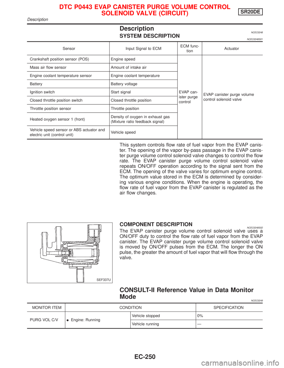
COMPONENT DESCRIPTIONNCEC0248S02The EVAP canister purge volume control solenoid valve uses a
ON/OFF duty to control the flow rate of fuel vapor from the EVAP
canister. The EVAP canister purge volume control solenoid valve
is moved by ON/OFF pulses from the ECM. The longer the ON
pulse, the greater the amount of fuel vapor that will flow through the
valve.
CONSULT-II Reference Value in Data Monitor
Mode
NCEC0249
MONITOR ITEM CONDITION SPECIFICATION
PURG VOL C/VIEngine: RunningVehicle stopped 0%
Vehicle running Ð
SEF337U
DTC P0443 EVAP CANISTER PURGE VOLUME CONTROL
SOLENOID VALVE (CIRCUIT)SR20DE
Description
EC-250
Page 1051 of 2267
ECM Terminals and Reference ValueNCEC0250Specification data are reference values and are measured between each terminal and 48 (ECM ground).
TERMI-
NAL
NO.WIRE
COLORITEM CONDITION DATA (DC Voltage)
14 P/BEVAP canister purge
volume control solenoid
valve (ON/OFF duty)[Engine is running]
IWarm-up condition
IIdle speedBATTERY VOLTAGE
(11 - 14V)
[Engine is running]
IWarm-up condition
I2,000 rpm5 - 12V
SEF975W
On Board Diagnosis LogicNCEC0251
DTC No. Malfunction is detected when ... Check Items (Possible Cause)
P0443
0443IAn improper voltage signal is sent to ECM through the
valve.IHarness or connectors
(The valve circuit is open or shorted.)
IEVAP canister purge volume control solenoid
valve
DTC Confirmation ProcedureNCEC0252NOTE:
If ªDTC Confirmation Procedureº has been previously conducted,
always turn ignition switch ªOFFº and wait at least 9 seconds
before conducting the next test.
TESTING CONDITION:
Before performing the following procedure, confirm battery
voltage is more than 11V.
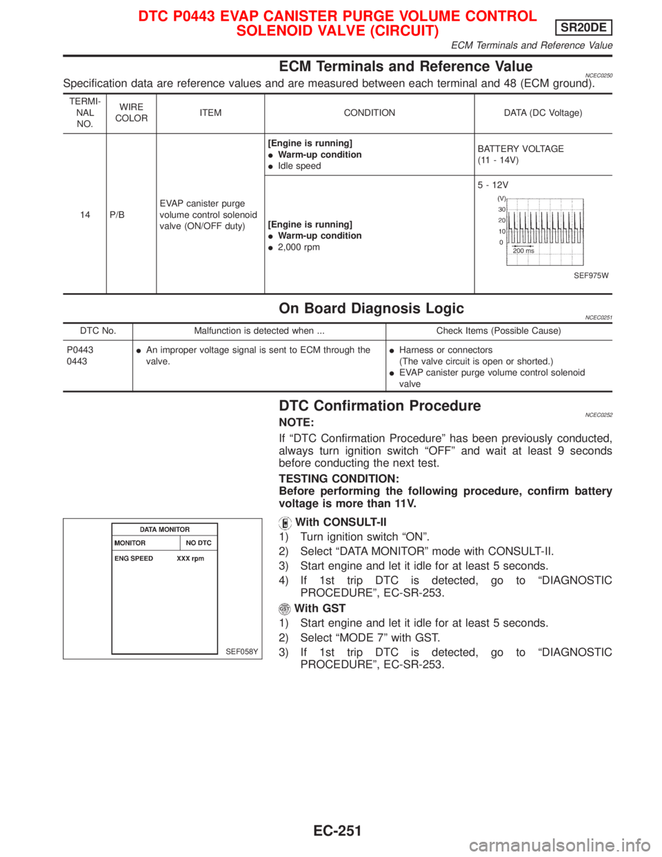
With CONSULT-II
1) Turn ignition switch ªONº.
2) Select ªDATA MONITORº mode with CONSULT-II.
3) Start engine and let it idle for at least 5 seconds.
4) If 1st trip DTC is detected, go to ªDIAGNOSTIC
PROCEDUREº, EC-SR-253.
With GST
1) Start engine and let it idle for at least 5 seconds.
2) Select ªMODE 7º with GST.
3) If 1st trip DTC is detected, go to ªDIAGNOSTIC
PROCEDUREº, EC-SR-253.
SEF058Y
DTC P0443 EVAP CANISTER PURGE VOLUME CONTROL
SOLENOID VALVE (CIRCUIT)SR20DE
ECM Terminals and Reference Value
EC-251