1999 NISSAN PRIMERA Control
[x] Cancel search: ControlPage 798 of 2267
![NISSAN PRIMERA 1999 Electronic Repair Manual Crankshaft Position Sensor (POS)NCEC0558
Terminal No. (Polarity) ResistanceW[at 25ÉC (77ÉF)]
3 (+) - 1 (þ)
Except 0 or¥ 2 (+) - 1 (þ)
3 (+) - 2 (þ)
Camshaft Position Sensor (PHASE)NCEC0559
Termi NISSAN PRIMERA 1999 Electronic Repair Manual Crankshaft Position Sensor (POS)NCEC0558
Terminal No. (Polarity) ResistanceW[at 25ÉC (77ÉF)]
3 (+) - 1 (þ)
Except 0 or¥ 2 (+) - 1 (þ)
3 (+) - 2 (þ)
Camshaft Position Sensor (PHASE)NCEC0559
Termi](/manual-img/5/57377/w960_57377-797.png)
Crankshaft Position Sensor (POS)NCEC0558
Terminal No. (Polarity) ResistanceW[at 25ÉC (77ÉF)]
3 (+) - 1 (þ)
Except 0 or¥ 2 (+) - 1 (þ)
3 (+) - 2 (þ)
Camshaft Position Sensor (PHASE)NCEC0559
Terminal No. (Polarity) ResistanceW[at 25ÉC (77ÉF)]
3 (+) - 1 (þ)
Except 0 or¥ 2 (+) - 1 (þ)
3 (+) - 2 (þ)
EGR Volume Control Valve (If so equipped)NCEC0560
Terminal No. ResistanceW[at 20ÉC (68ÉF)]
1-2
20-24 2-3
4-5
5-6
EGR Temperature Sensor (If so equipped)NCEC0472
EGR temperature
ÉC (ÉF)Voltage
VResistance
MW
0 (32) 4.56 0.62 - 1.05
50 (122) 2.25 0.065 - 0.094
100 (212) 0.59 0.011 - 0.015
EVAP Canister Purge Volume Control ValveNCEC0481
Resistance [at 20ÉC (68ÉF)]W31-35
IACV-AAC ValveNCEC0474
Terminal No. ResistanceW[at 20ÉC (68ÉF)]
1-2
20-24 2-3
4-5
5-6
InjectorNCEC0475
Resistance [at 25ÉC (77ÉF)]W13.5 - 17.5
SERVICE DATA AND SPECIFICATIONS (SDS)
Crankshaft Position Sensor (POS)
EC-356
Page 801 of 2267
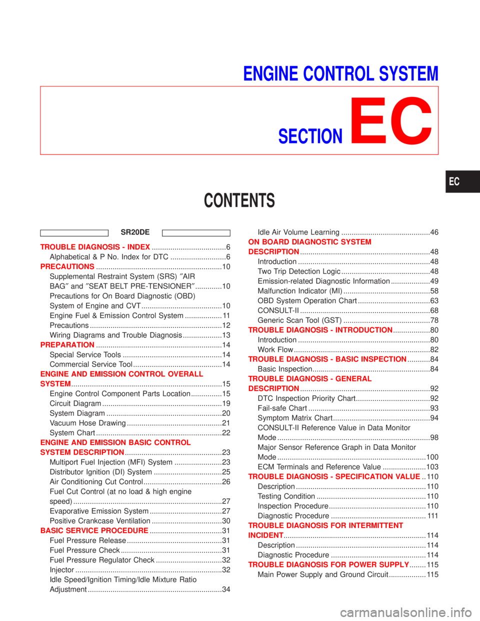
ENGINE CONTROL SYSTEM
SECTION
EC
CONTENTS
SR20DE
TROUBLE DIAGNOSIS - INDEX....................................6
Alphabetical & P No. Index for DTC ...........................6
PRECAUTIONS.............................................................10
Supplemental Restraint System (SRS)²AIR
BAG²and²SEAT BELT PRE-TENSIONER².............10
Precautions for On Board Diagnostic (OBD)
System of Engine and CVT .......................................10
Engine Fuel & Emission Control System .................. 11
Precautions ................................................................12
Wiring Diagrams and Trouble Diagnosis ...................13
PREPARATION.............................................................14
Special Service Tools ................................................14
Commercial Service Tool ...........................................14
ENGINE AND EMISSION CONTROL OVERALL
SYSTEM.........................................................................15
Engine Control Component Parts Location ...............15
Circuit Diagram ..........................................................19
System Diagram ........................................................20
Vacuum Hose Drawing ..............................................21
System Chart .............................................................22
ENGINE AND EMISSION BASIC CONTROL
SYSTEM DESCRIPTION...............................................23
Multiport Fuel Injection (MFI) System .......................23
Distributor Ignition (DI) System .................................25
Air Conditioning Cut Control ......................................26
Fuel Cut Control (at no load & high engine
speed) ........................................................................27
Evaporative Emission System ...................................27
Positive Crankcase Ventilation ..................................30
BASIC SERVICE PROCEDURE...................................31
Fuel Pressure Release ..............................................31
Fuel Pressure Check .................................................31
Fuel Pressure Regulator Check ................................32
Injector .......................................................................32
Idle Speed/Ignition Timing/Idle Mixture Ratio
Adjustment .................................................................34Idle Air Volume Learning ...........................................46
ON BOARD DIAGNOSTIC SYSTEM
DESCRIPTION...............................................................48
Introduction ................................................................48
Two Trip Detection Logic ...........................................48
Emission-related Diagnostic Information ...................49
Malfunction Indicator (MI) ..........................................58
OBD System Operation Chart ...................................63
CONSULT-II ...............................................................68
Generic Scan Tool (GST) ..........................................78
TROUBLE DIAGNOSIS - INTRODUCTION..................80
Introduction ................................................................80
Work Flow ..................................................................82
TROUBLE DIAGNOSIS - BASIC INSPECTION...........84
Basic Inspection.........................................................84
TROUBLE DIAGNOSIS - GENERAL
DESCRIPTION...............................................................92
DTC Inspection Priority Chart....................................92
Fail-safe Chart ...........................................................93
Symptom Matrix Chart ...............................................94
CONSULT-II Reference Value in Data Monitor
Mode ..........................................................................98
Major Sensor Reference Graph in Data Monitor
Mode ........................................................................100
ECM Terminals and Reference Value .....................103
TROUBLE DIAGNOSIS - SPECIFICATION VALUE.. 110
Description ............................................................... 110
Testing Condition ..................................................... 110
Inspection Procedure ............................................... 110
Diagnostic Procedure .............................................. 111
TROUBLE DIAGNOSIS FOR INTERMITTENT
INCIDENT..................................................................... 114
Description ............................................................... 114
Diagnostic Procedure .............................................. 114
TROUBLE DIAGNOSIS FOR POWER SUPPLY........ 115
Main Power Supply and Ground Circuit .................. 115
EC
Page 804 of 2267
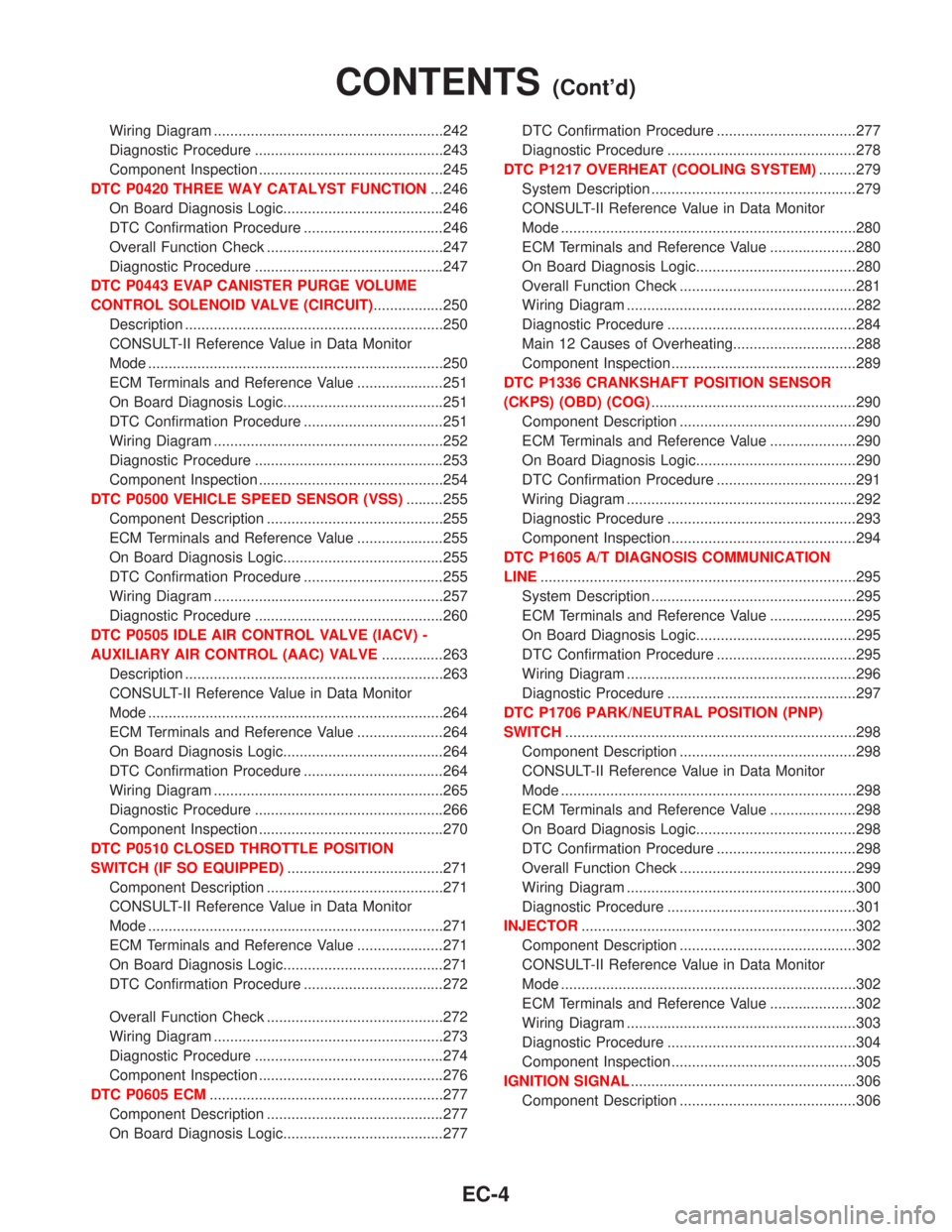
Wiring Diagram ........................................................242
Diagnostic Procedure ..............................................243
Component Inspection .............................................245
DTC P0420 THREE WAY CATALYST FUNCTION...246
On Board Diagnosis Logic.......................................246
DTC Confirmation Procedure ..................................246
Overall Function Check ...........................................247
Diagnostic Procedure ..............................................247
DTC P0443 EVAP CANISTER PURGE VOLUME
CONTROL SOLENOID VALVE (CIRCUIT).................250
Description ...............................................................250
CONSULT-II Reference Value in Data Monitor
Mode ........................................................................250
ECM Terminals and Reference Value .....................251
On Board Diagnosis Logic.......................................251
DTC Confirmation Procedure ..................................251
Wiring Diagram ........................................................252
Diagnostic Procedure ..............................................253
Component Inspection .............................................254
DTC P0500 VEHICLE SPEED SENSOR (VSS).........255
Component Description ...........................................255
ECM Terminals and Reference Value .....................255
On Board Diagnosis Logic.......................................255
DTC Confirmation Procedure ..................................255
Wiring Diagram ........................................................257
Diagnostic Procedure ..............................................260
DTC P0505 IDLE AIR CONTROL VALVE (IACV) -
AUXILIARY AIR CONTROL (AAC) VALVE...............263
Description ...............................................................263
CONSULT-II Reference Value in Data Monitor
Mode ........................................................................264
ECM Terminals and Reference Value .....................264
On Board Diagnosis Logic.......................................264
DTC Confirmation Procedure ..................................264
Wiring Diagram ........................................................265
Diagnostic Procedure ..............................................266
Component Inspection .............................................270
DTC P0510 CLOSED THROTTLE POSITION
SWITCH (IF SO EQUIPPED)......................................271
Component Description ...........................................271
CONSULT-II Reference Value in Data Monitor
Mode ........................................................................271
ECM Terminals and Reference Value .....................271
On Board Diagnosis Logic.......................................271
DTC Confirmation Procedure ..................................272
Overall Function Check ...........................................272
Wiring Diagram ........................................................273
Diagnostic Procedure ..............................................274
Component Inspection .............................................276
DTC P0605 ECM.........................................................277
Component Description ...........................................277
On Board Diagnosis Logic.......................................277DTC Confirmation Procedure ..................................277
Diagnostic Procedure ..............................................278
DTC P1217 OVERHEAT (COOLING SYSTEM).........279
System Description ..................................................279
CONSULT-II Reference Value in Data Monitor
Mode ........................................................................280
ECM Terminals and Reference Value .....................280
On Board Diagnosis Logic.......................................280
Overall Function Check ...........................................281
Wiring Diagram ........................................................282
Diagnostic Procedure ..............................................284
Main 12 Causes of Overheating..............................288
Component Inspection .............................................289
DTC P1336 CRANKSHAFT POSITION SENSOR
(CKPS) (OBD) (COG)..................................................290
Component Description ...........................................290
ECM Terminals and Reference Value .....................290
On Board Diagnosis Logic.......................................290
DTC Confirmation Procedure ..................................291
Wiring Diagram ........................................................292
Diagnostic Procedure ..............................................293
Component Inspection .............................................294
DTC P1605 A/T DIAGNOSIS COMMUNICATION
LINE.............................................................................295
System Description ..................................................295
ECM Terminals and Reference Value .....................295
On Board Diagnosis Logic.......................................295
DTC Confirmation Procedure ..................................295
Wiring Diagram ........................................................296
Diagnostic Procedure ..............................................297
DTC P1706 PARK/NEUTRAL POSITION (PNP)
SWITCH.......................................................................298
Component Description ...........................................298
CONSULT-II Reference Value in Data Monitor
Mode ........................................................................298
ECM Terminals and Reference Value .....................298
On Board Diagnosis Logic.......................................298
DTC Confirmation Procedure ..................................298
Overall Function Check ...........................................299
Wiring Diagram ........................................................300
Diagnostic Procedure ..............................................301
INJECTOR...................................................................302
Component Description ...........................................302
CONSULT-II Reference Value in Data Monitor
Mode ........................................................................302
ECM Terminals and Reference Value .....................302
Wiring Diagram ........................................................303
Diagnostic Procedure ..............................................304
Component Inspection .............................................305
IGNITION SIGNAL.......................................................306
Component Description ...........................................306
CONTENTS(Cont'd)
EC-4
Page 805 of 2267
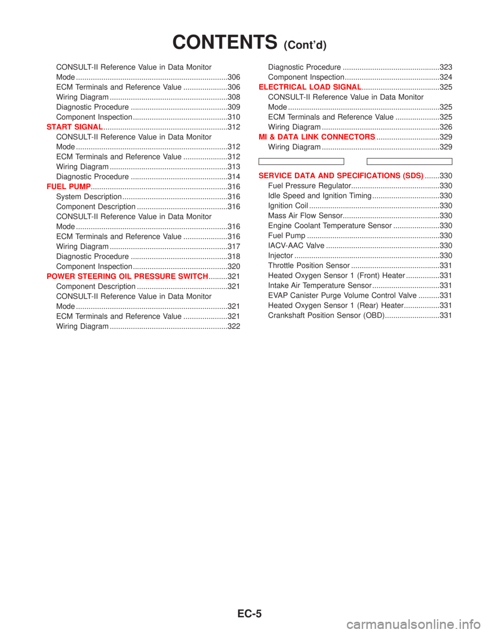
CONSULT-II Reference Value in Data Monitor
Mode ........................................................................306
ECM Terminals and Reference Value .....................306
Wiring Diagram ........................................................308
Diagnostic Procedure ..............................................309
Component Inspection .............................................310
START SIGNAL...........................................................312
CONSULT-II Reference Value in Data Monitor
Mode ........................................................................312
ECM Terminals and Reference Value .....................312
Wiring Diagram ........................................................313
Diagnostic Procedure ..............................................314
FUEL PUMP.................................................................316
System Description ..................................................316
Component Description ...........................................316
CONSULT-II Reference Value in Data Monitor
Mode ........................................................................316
ECM Terminals and Reference Value .....................316
Wiring Diagram ........................................................317
Diagnostic Procedure ..............................................318
Component Inspection .............................................320
POWER STEERING OIL PRESSURE SWITCH.........321
Component Description ...........................................321
CONSULT-II Reference Value in Data Monitor
Mode ........................................................................321
ECM Terminals and Reference Value .....................321
Wiring Diagram ........................................................322Diagnostic Procedure ..............................................323
Component Inspection .............................................324
ELECTRICAL LOAD SIGNAL.....................................325
CONSULT-II Reference Value in Data Monitor
Mode ........................................................................325
ECM Terminals and Reference Value .....................325
Wiring Diagram ........................................................326
MI & DATA LINK CONNECTORS..............................329
Wiring Diagram ........................................................329
SERVICE DATA AND SPECIFICATIONS (SDS).......330
Fuel Pressure Regulator..........................................330
Idle Speed and Ignition Timing ................................330
Ignition Coil ..............................................................330
Mass Air Flow Sensor..............................................330
Engine Coolant Temperature Sensor ......................330
Fuel Pump ...............................................................330
IACV-AAC Valve ......................................................330
Injector .....................................................................330
Throttle Position Sensor ..........................................331
Heated Oxygen Sensor 1 (Front) Heater ................331
Intake Air Temperature Sensor ................................331
EVAP Canister Purge Volume Control Valve ..........331
Heated Oxygen Sensor 1 (Rear) Heater.................331
Crankshaft Position Sensor (OBD)..........................331
CONTENTS(Cont'd)
EC-5
Page 807 of 2267
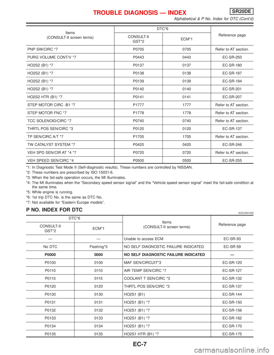
Items
(CONSULT-II screen terms)DTC*6
Reference page
CONSULT-II
GST*2ECM*1
PNP SW/CIRC *7 P0705 0705 Refer to AT section.
PURG VOLUME CONT/V *7 P0443 0443 EC-SR-250
HO2S2 (B1) *7 P0137 0137 EC-SR-180
HO2S2 (B1) *7 P0138 0138 EC-SR-187
HO2S2 (B1) *7 P0139 0139 EC-SR-194
HO2S2 (B1) *7 P0140 0140 EC-SR-201
HO2S2 HTR (B1) *7 P0141 0141 EC-SR-207
STEP MOTOR CIRC -B1 *7 P1777 1777 Refer to AT section.
STEP MOTOR FNC *7 P1778 1778 Refer to AT section.
TCC SOLENOID/CIRC *7 P0740 0740 Refer to AT section.
THRTL POS SEN/CIRC *3 P0120 0120 EC-SR-137
TP SEN/CIRC A/T *7 P1705 1705 Refer to AT section.
TW CATALYST SYSTEM *7 P0420 0420 EC-SR-246
VEH SPD SEN/CIR AT *4 *7 P0720 0720 Refer to AT section.
VEH SPEED SEN/CIRC *4 P0500 0500 EC-SR-255
*1: In Diagnostic Test Mode II (Self-diagnostic results). These numbers are controlled by NISSAN.
*2: These numbers are prescribed by ISO 15031-6.
*3: When the fail-safe operation occurs, the MI illuminates.
*4: The MI illuminates when the ªSecondary speed sensor signalº and the ªVehicle speed sensor signalº meet the fail-safe condition at
the same time.
*5: While engine is running.
*6: 1st trip DTC No. is the same as DTC No.
*7: Not available for ªEastern Europe modelsº.
P NO. INDEX FOR DTCNCEC0001S02
DTC*6
Items
(CONSULT-II screen terms)Reference page
CONSULT-II
GST*2ECM*1
Ð Ð Unable to access ECM EC-SR-93
No DTC Flashing*5 NO SELF DIAGNOSTIC FAILURE INDICATED EC-SR-59
P0000 0000 NO SELF DIAGNOSTIC FAILURE INDICATED Ð
P0100 0100 MAF SEN/CIRCUIT*3 EC-SR-120
P0110 0110 AIR TEMP SEN/CIRC *7 EC-SR-127
P0115 0115 COOLANT T SEN/CIRC *3 EC-SR-132
P0120 0120 THRTL POS SEN/CIRC *3 EC-SR-137
P0130 0130 HO2S1 (B1) EC-SR-144
P0131 0131 HO2S1 (B1) *7 EC-SR-150
P0132 0132 HO2S1 (B1) *7 EC-SR-156
P0133 0133 HO2S1 (B1) *7 EC-SR-162
P0134 0134 HO2S1 (B1) *7 EC-SR-170
P0135 0135 HO2S1 HTR (B1) *7 EC-SR-175
TROUBLE DIAGNOSIS Ð INDEXSR20DE
Alphabetical & P No. Index for DTC (Cont'd)
EC-7
Page 809 of 2267
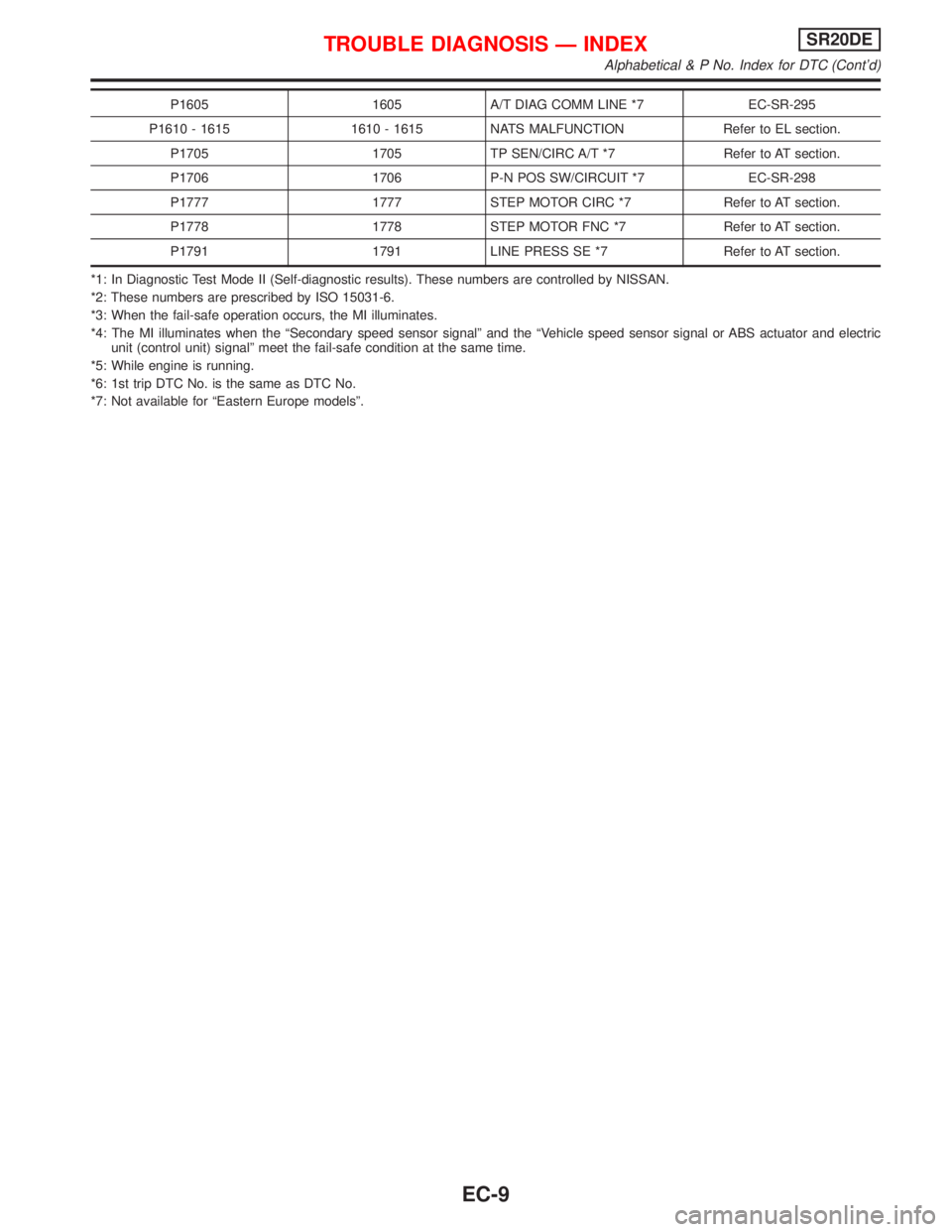
P1605 1605 A/T DIAG COMM LINE *7 EC-SR-295
P1610 - 1615 1610 - 1615 NATS MALFUNCTION Refer to EL section.
P1705 1705 TP SEN/CIRC A/T *7 Refer to AT section.
P1706 1706 P-N POS SW/CIRCUIT *7 EC-SR-298
P1777 1777 STEP MOTOR CIRC *7 Refer to AT section.
P1778 1778 STEP MOTOR FNC *7 Refer to AT section.
P1791 1791 LINE PRESS SE *7 Refer to AT section.
*1: In Diagnostic Test Mode II (Self-diagnostic results). These numbers are controlled by NISSAN.
*2: These numbers are prescribed by ISO 15031-6.
*3: When the fail-safe operation occurs, the MI illuminates.
*4: The MI illuminates when the ªSecondary speed sensor signalº and the ªVehicle speed sensor signal or ABS actuator and electric
unit (control unit) signalº meet the fail-safe condition at the same time.
*5: While engine is running.
*6: 1st trip DTC No. is the same as DTC No.
*7: Not available for ªEastern Europe modelsº.
TROUBLE DIAGNOSIS Ð INDEXSR20DE
Alphabetical & P No. Index for DTC (Cont'd)
EC-9
Page 810 of 2267
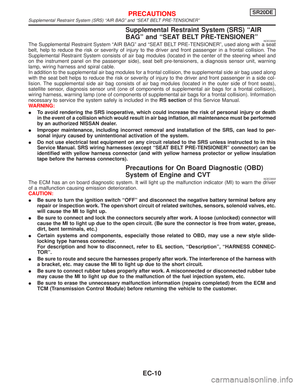
Supplemental Restraint System (SRS) ªAIR
BAGº and ªSEAT BELT PRE-TENSIONERº
NCEC0002The Supplemental Restraint System ªAIR BAGº and ªSEAT BELT PRE-TENSIONERº, used along with a seat
belt, help to reduce the risk or severity of injury to the driver and front passenger in a frontal collision. The
Supplemental Restraint System consists of air bag modules (located in the center of the steering wheel and
on the instrument panel on the passenger side), seat belt pre-tensioners, a diagnosis sensor unit, warning
lamp, wiring harness and spiral cable.
In addition to the supplemental air bag modules for a frontal collision, the supplemental side air bag used along
with the seat belt helps to reduce the risk or severity of injury to the driver and front passenger in a side col-
lision. The supplemental side air bag consists of air bag modules (located in the outer side of front seats),
satellite sensor, diagnosis sensor unit (one of components of supplemental air bags for a frontal collision),
wiring harness, warning lamp (one of components of supplemental air bags for a frontal collision). Information
necessary to service the system safely is included in theRS sectionof this Service Manual.
WARNING:
ITo avoid rendering the SRS inoperative, which could increase the risk of personal injury or death
in the event of a collision which would result in air bag inflation, all maintenance must be performed
by an authorized NISSAN dealer.
IImproper maintenance, including incorrect removal and installation of the SRS, can lead to per-
sonal injury caused by unintentional activation of the system.
IDo not use electrical test equipment on any circuit related to the SRS unless instructed to in this
Service Manual. SRS wiring harnesses (except ªSEAT BELT PRE-TENSIONERº connector) can be
identified with yellow harness connector (and with yellow harness protector or yellow insulation
tape before the harness connectors).
Precautions for On Board Diagnostic (OBD)
System of Engine and CVT
NCEC0003The ECM has an on board diagnostic system. It will light up the malfunction indicator (MI) to warn the driver
of a malfunction causing emission deterioration.
CAUTION:
IBe sure to turn the ignition switch ªOFFº and disconnect the negative battery terminal before any
repair or inspection work. The open/short circuit of related switches, sensors, solenoid valves, etc.
will cause the MI to light up.
IBe sure to connect and lock the connectors securely after work. A loose (unlocked) connector will
cause the MI to light up due to the open circuit. (Be sure the connector is free from water, grease,
dirt, bent terminals, etc.)
ICertain systems and components, especially those related to OBD, may use a new style slide-
locking type harness connector.
For description and how to disconnect, refer to EL section, ªDescriptionº, ªHARNESS CONNEC-
TORº.
IBe sure to route and secure the harnesses properly after work. The interference of the harness with
a bracket, etc. may cause the MI to light up due to the short circuit.
IBe sure to connect rubber tubes properly after work. A misconnected or disconnected rubber tube
may cause the MI to light up due to the malfunction of the fuel injection system, etc.
IBe sure to erase the unnecessary malfunction information (repairs completed) from the ECM and
TCM (Transmission Control Module) before returning the vehicle to the customer.
PRECAUTIONSSR20DE
Supplemental Restraint System (SRS) ªAIR BAGº and ªSEAT BELT PRE-TENSIONERº
EC-10
Page 811 of 2267
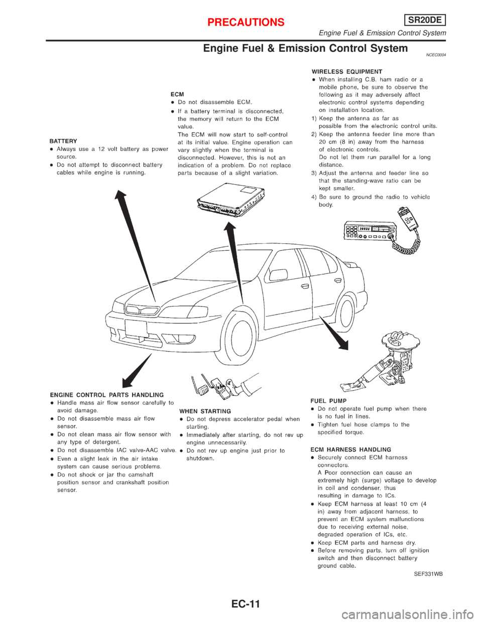
Engine Fuel & Emission Control SystemNCEC0004
SEF331WB
PRECAUTIONSSR20DE
Engine Fuel & Emission Control System
EC-11