Page 747 of 2267
DescriptionNCEC0349SYSTEM DESCRIPTIONNCEC0349S01
Sensor Input Signal to ECMECM
functionActuator
Crankshaft position sensor (POS) Engine speed
EGR control EGR volume control valve Mass air flow sensor Amount of intake air
Engine coolant temperature sensor Engine coolant temperature
Ignition switch Start signal
Throttle position sensor Throttle position
Vehicle speed sensor or ABS actuator and
electric unit (control unit)Vehicle speed
Battery Battery voltage
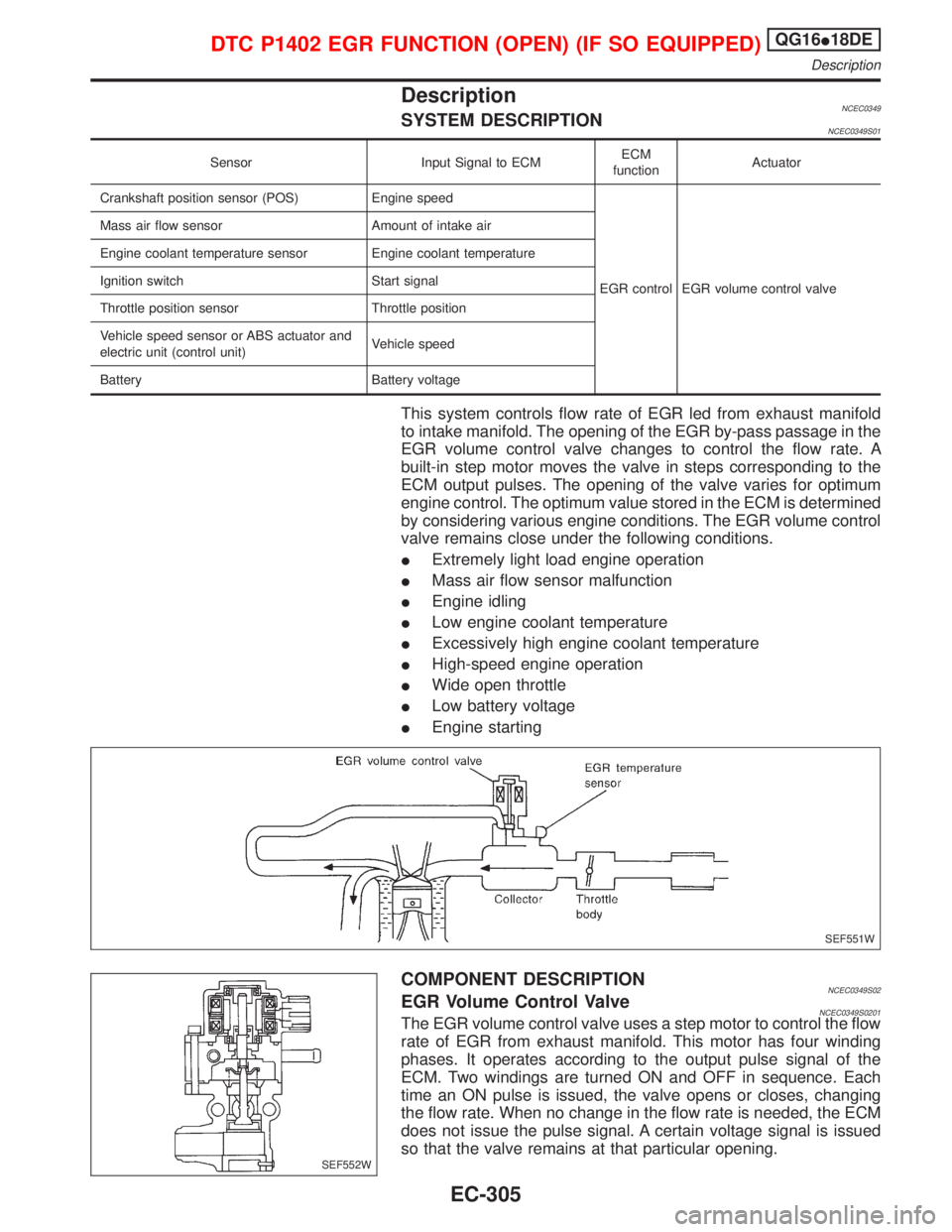
This system controls flow rate of EGR led from exhaust manifold
to intake manifold. The opening of the EGR by-pass passage in the
EGR volume control valve changes to control the flow rate. A
built-in step motor moves the valve in steps corresponding to the
ECM output pulses. The opening of the valve varies for optimum
engine control. The optimum value stored in the ECM is determined
by considering various engine conditions. The EGR volume control
valve remains close under the following conditions.
IExtremely light load engine operation
IMass air flow sensor malfunction
IEngine idling
ILow engine coolant temperature
IExcessively high engine coolant temperature
IHigh-speed engine operation
IWide open throttle
ILow battery voltage
IEngine starting
COMPONENT DESCRIPTIONNCEC0349S02EGR Volume Control ValveNCEC0349S0201The EGR volume control valve uses a step motor to control the flow
rate of EGR from exhaust manifold. This motor has four winding
phases. It operates according to the output pulse signal of the
ECM. Two windings are turned ON and OFF in sequence. Each
time an ON pulse is issued, the valve opens or closes, changing
the flow rate. When no change in the flow rate is needed, the ECM
does not issue the pulse signal. A certain voltage signal is issued
so that the valve remains at that particular opening.
SEF551W
SEF552W
DTC P1402 EGR FUNCTION (OPEN) (IF SO EQUIPPED)QG16I18DE
Description
EC-305
Page 748 of 2267
CONSULT-II Reference Value in Data Monitor
Mode
NCEC0539Specification data are reference values.
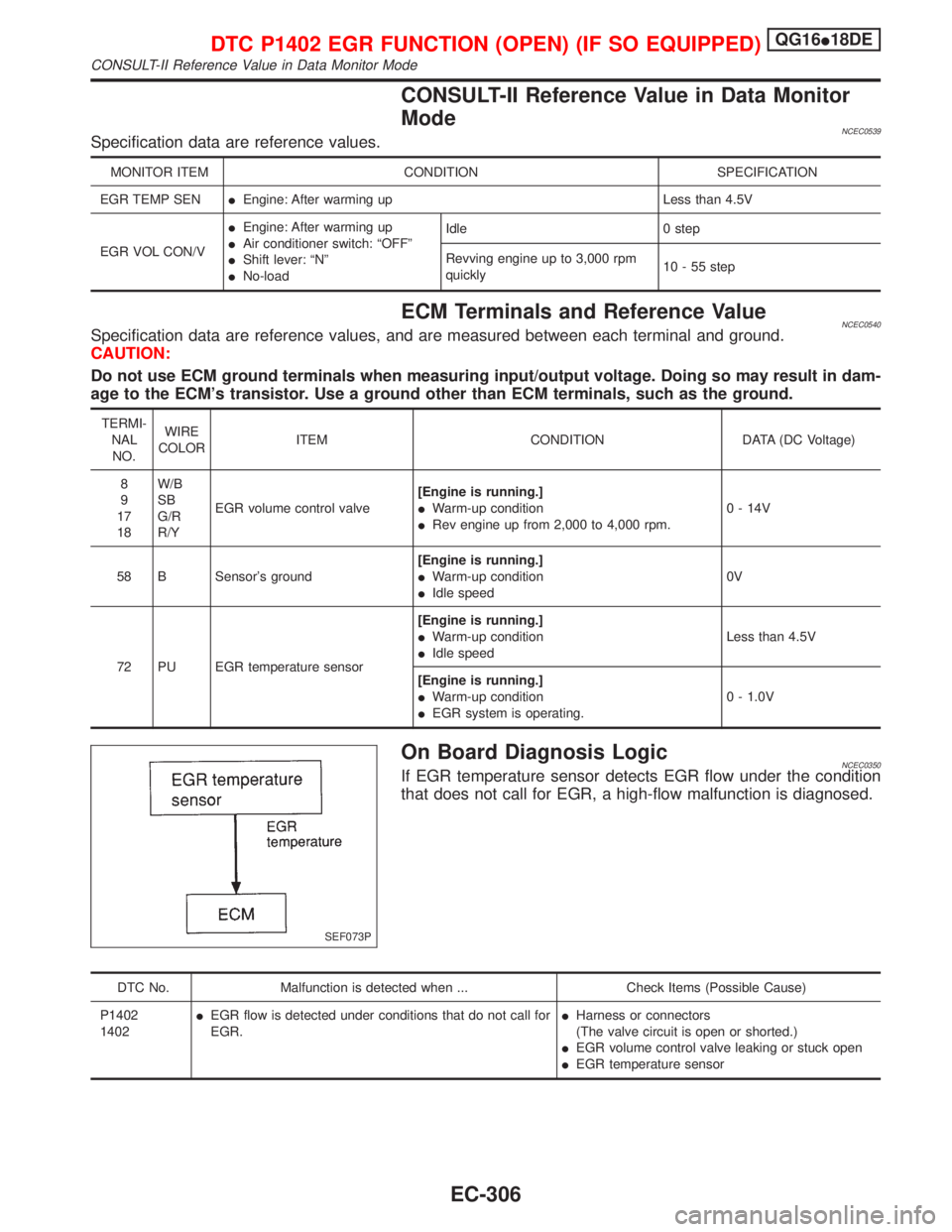
MONITOR ITEM CONDITION SPECIFICATION
EGR TEMP SENIEngine: After warming up Less than 4.5V
EGR VOL CON/VIEngine: After warming up
IAir conditioner switch: ªOFFº
IShift lever: ªNº
INo-loadIdle 0 step
Revving engine up to 3,000 rpm
quickly10 - 55 step
ECM Terminals and Reference ValueNCEC0540Specification data are reference values, and are measured between each terminal and ground.
CAUTION:
Do not use ECM ground terminals when measuring input/output voltage. Doing so may result in dam-
age to the ECM's transistor. Use a ground other than ECM terminals, such as the ground.
TERMI-
NAL
NO.WIRE
COLORITEM CONDITION DATA (DC Voltage)
8
9
17
18W/B
SB
G/R
R/YEGR volume control valve[Engine is running.]
IWarm-up condition
IRev engine up from 2,000 to 4,000 rpm.0 - 14V
58 B Sensor's ground[Engine is running.]
IWarm-up condition
IIdle speed0V
72 PU EGR temperature sensor[Engine is running.]
IWarm-up condition
IIdle speedLess than 4.5V
[Engine is running.]
IWarm-up condition
IEGR system is operating.0 - 1.0V
On Board Diagnosis LogicNCEC0350If EGR temperature sensor detects EGR flow under the condition
that does not call for EGR, a high-flow malfunction is diagnosed.
DTC No. Malfunction is detected when ... Check Items (Possible Cause)
P1402
1402IEGR flow is detected under conditions that do not call for
EGR.IHarness or connectors
(The valve circuit is open or shorted.)
IEGR volume control valve leaking or stuck open
IEGR temperature sensor
SEF073P
DTC P1402 EGR FUNCTION (OPEN) (IF SO EQUIPPED)QG16I18DE
CONSULT-II Reference Value in Data Monitor Mode
EC-306
Page 752 of 2267
Diagnostic ProcedureNCEC0353
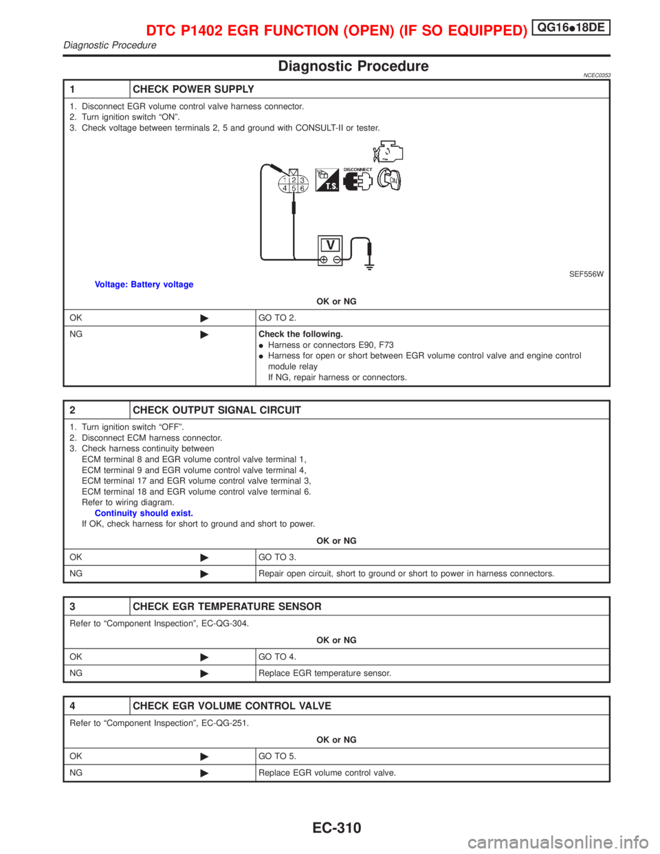
1 CHECK POWER SUPPLY
1. Disconnect EGR volume control valve harness connector.
2. Turn ignition switch ªONº.
3. Check voltage between terminals 2, 5 and ground with CONSULT-II or tester.
SEF556WVoltage: Battery voltage
OK or NG
OK©GO TO 2.
NG©Check the following.
IHarness or connectors E90, F73
IHarness for open or short between EGR volume control valve and engine control
module relay
If NG, repair harness or connectors.
2 CHECK OUTPUT SIGNAL CIRCUIT
1. Turn ignition switch ªOFFº.
2. Disconnect ECM harness connector.
3. Check harness continuity between
ECM terminal 8 and EGR volume control valve terminal 1,
ECM terminal 9 and EGR volume control valve terminal 4,
ECM terminal 17 and EGR volume control valve terminal 3,
ECM terminal 18 and EGR volume control valve terminal 6.
Refer to wiring diagram.
Continuity should exist.
If OK, check harness for short to ground and short to power.
OK or NG
OK©GO TO 3.
NG©Repair open circuit, short to ground or short to power in harness connectors.
3 CHECK EGR TEMPERATURE SENSOR
Refer to ªComponent Inspectionº, EC-QG-304.
OK or NG
OK©GO TO 4.
NG©Replace EGR temperature sensor.
4 CHECK EGR VOLUME CONTROL VALVE
Refer to ªComponent Inspectionº, EC-QG-251.
OK or NG
OK©GO TO 5.
NG©Replace EGR volume control valve.
DTC P1402 EGR FUNCTION (OPEN) (IF SO EQUIPPED)QG16I18DE
Diagnostic Procedure
EC-310
Page 754 of 2267
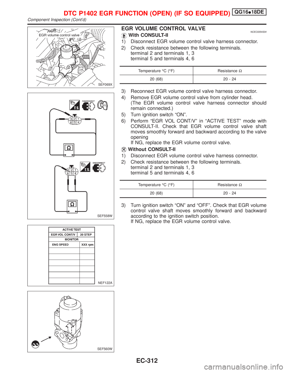
EGR VOLUME CONTROL VALVENCEC0354S04With CONSULT-II
1) Disconnect EGR volume control valve harness connector.
2) Check resistance between the following terminals.
terminal 2 and terminals 1, 3
terminal 5 and terminals 4, 6
Temperature ÉC (ÉF) ResistanceW
20 (68) 20 - 24
3) Reconnect EGR volume control valve harness connector.
4) Remove EGR volume control valve from cylinder head.
(The EGR volume control valve harness connector should
remain connected.)
5) Turn ignition switch ªONº.
6) Perform ªEGR VOL CONT/Vº in ªACTIVE TESTº mode with
CONSULT-II. Check that EGR volume control valve shaft
moves smoothly forward and backward according to the valve
opening
If NG, replace the EGR volume control valve.
Without CONSULT-II
1) Disconnect EGR volume control valve harness connector.
2) Check resistance between the following terminals.
terminal 2 and terminals 1, 3
terminal 5 and terminals 4, 6
Temperature ÉC (ÉF) ResistanceW
20 (68) 20 - 24
3) Turn ignition switch ªONº and ªOFFº. Check that EGR volume
control valve shaft moves smoothly forward and backward
according to the ignition switch position.
If NG, replace the EGR volume control valve.
SEF069X
SEF558W
NEF122A
SEF560W
DTC P1402 EGR FUNCTION (OPEN) (IF SO EQUIPPED)QG16I18DE
Component Inspection (Cont'd)
EC-312
Page 760 of 2267
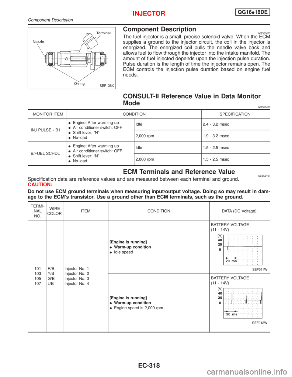
Component DescriptionNCEC0435The fuel injector is a small, precise solenoid valve. When the ECM
supplies a ground to the injector circuit, the coil in the injector is
energized. The energized coil pulls the needle valve back and
allows fuel to flow through the injector into the intake manifold. The
amount of fuel injected depends upon the injection pulse duration.
Pulse duration is the length of time the injector remains open. The
ECM controls the injection pulse duration based on engine fuel
needs.
CONSULT-II Reference Value in Data Monitor
Mode
NCEC0436
MONITOR ITEM CONDITION SPECIFICATION
INJ PULSE - B1IEngine: After warming up
IAir conditioner switch: OFF
IShift lever: ªNº
INo-loadIdle 2.4 - 3.2 msec
2,000 rpm 1.9 - 3.2 msec
B/FUEL SCHDLIEngine: After warming up
IAir conditioner switch: OFF
IShift lever: ªNº
INo-loadIdle 1.5 - 2.5 msec
2,000 rpm 1.5 - 2.5 msec
ECM Terminals and Reference ValueNCEC0437Specification data are reference values and are measured between each terminal and ground.
CAUTION:
Do not use ECM ground terminals when measuring input/output voltage. Doing so may result in dam-
age to the ECM's transistor. Use a ground other than ECM terminals, such as the ground.
TERMI-
NAL
NO.WIRE
COLORITEM CONDITION DATA (DC Voltage)
101
103
105
107R/B
Y/B
G/B
L/BInjector No. 1
Injector No. 2
Injector No. 3
Injector No. 4[Engine is running]
IWarm-up condition
IIdle speedBATTERY VOLTAGE
(11 - 14V)
SEF011W
[Engine is running]
IWarm-up condition
IEngine speed is 2,000 rpmBATTERY VOLTAGE
(11 - 14V)
SEF012W
SEF138X
INJECTORQG16I18DE
Component Description
EC-318
Page 766 of 2267
Wiring DiagramNCEC0545
YEC793
ENGINE
CONTROL
MODULE
RELAY
CONDENSER Refer to EL-POWER. BATTERY
: Detectable line for DTC
: Non-detectable line for DTC
Next pageNext page
IGNITION SIGNALQG16I18DE
Wiring Diagram
EC-324
Page 778 of 2267
System DescriptionNCEC0444
Sensor Input Signal to ECMECM func-
tionActuator
Camshaft position sensor (PHASE) Engine speed
Fuel pump
controlFuel pump relay
Ignition switch Start signal
The ECM activates the fuel pump for several seconds after the ignition switch is turned on to improve engine
startability. If the ECM receives a 180É signal from the camshaft position sensor, it knows that the engine is
rotating, and causes the pump to perform. If the 180É signal is not received when the ignition switch is on, the
engine stalls. The ECM stops pump operation and prevents battery discharging, thereby improving safety. The
ECM does not directly drive the fuel pump. It controls the ON/OFF fuel pump relay, which in turn controls the
fuel pump.
Condition Fuel pump operation
Ignition switch is turned to ON. Operates for 1 second
Engine running and cranking Operates
When engine is stopped (Signal is not sent from camshaft position sensor.) Stops in 1.5 seconds
Except as shown aboveStops
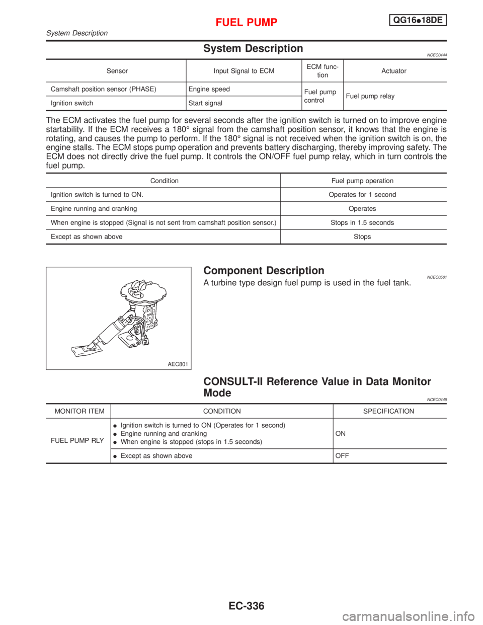
Component DescriptionNCEC0501A turbine type design fuel pump is used in the fuel tank.
CONSULT-II Reference Value in Data Monitor
Mode
NCEC0445
MONITOR ITEM CONDITION SPECIFICATION
FUEL PUMP RLYIIgnition switch is turned to ON (Operates for 1 second)
IEngine running and cranking
IWhen engine is stopped (stops in 1.5 seconds)ON
IExcept as shown above OFF
AEC801
FUEL PUMPQG16I18DE
System Description
EC-336
Page 789 of 2267
JEF147Y
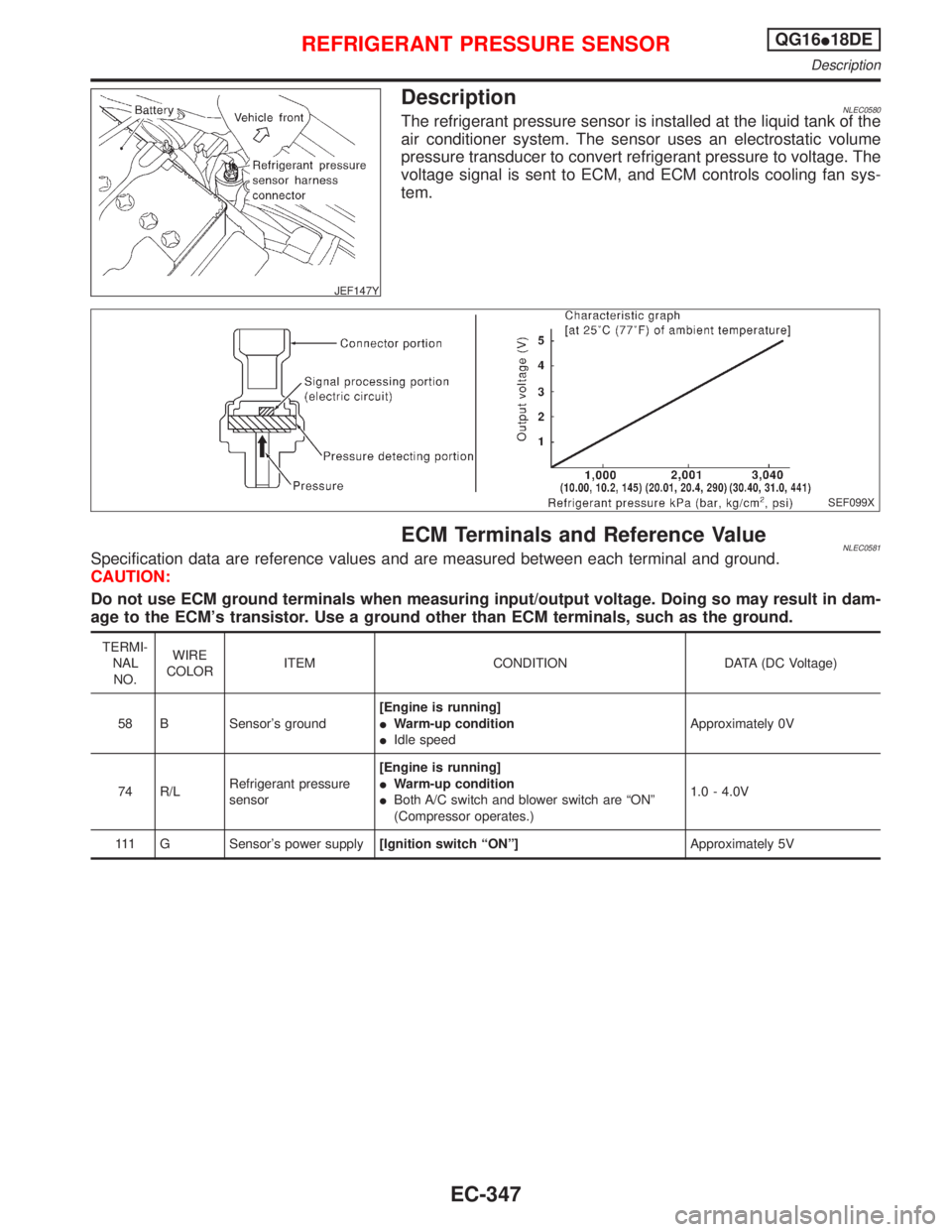
DescriptionNLEC0580The refrigerant pressure sensor is installed at the liquid tank of the
air conditioner system. The sensor uses an electrostatic volume
pressure transducer to convert refrigerant pressure to voltage. The
voltage signal is sent to ECM, and ECM controls cooling fan sys-
tem.
SEF099X
ECM Terminals and Reference ValueNLEC0581Specification data are reference values and are measured between each terminal and ground.
CAUTION:
Do not use ECM ground terminals when measuring input/output voltage. Doing so may result in dam-
age to the ECM's transistor. Use a ground other than ECM terminals, such as the ground.
TERMI-
NAL
NO.WIRE
COLORITEM CONDITION DATA (DC Voltage)
58 B Sensor's ground[Engine is running]
IWarm-up condition
IIdle speedApproximately 0V
74 R/LRefrigerant pressure
sensor[Engine is running]
IWarm-up condition
IBoth A/C switch and blower switch are ªONº
(Compressor operates.)1.0 - 4.0V
111 G Sensor's power supply[Ignition switch ªONº]Approximately 5V
REFRIGERANT PRESSURE SENSORQG16I18DE
Description
EC-347